Single-Phase to Three-Phase Inverter with Small DC-Link Capacitor for Motor Drive System
2019-03-07ZHOUYufeiHUANGWenxin
ZHOU Yufei,HUANG Wenxin
1.College of Electronic and Information Engineering,Nanjing University of Aeronautics and Astronautics,Nanjing 211106,P.R.China;
2.College of Automation Engineering,Nanjing University of Aeronautics and Astronautics,Nanjing 211106,P.R.China
Abstract:The electrolytic-capacitor-less(EL-cap-less)technique has been attracting more and more interests in these years.The EL-cap-less single-phase to three-phase inverter(STI)with front-end diode rectifier is applied to home electrical appliances.In EL-cap-less systems,film-type capacitor is used to suppress the high-frequency ripple components instead of smoothing the DC-link voltage.By using the EL-cap-less solution,reliability can be improved,lifetime can be increased and high power factor(PF)also can be realized.The EL-cap-less STI brings the opportunity to simplify system structure and lower cost.Because a certain DC-link capacitance is still required,the real PF is limited.T o further improve the PF,the ripple components of current references are made in synchronous with the DClink voltage.And the capacitance chosen guideline of the film-type capacitor also be presented.A prototype is built to verify its real performance.
Key words:AC-DC-AC converter;electrolytic-capacitor-less;high power factor
0 Introduction
As known to all,electronic equipments often suffer from high temperature for military and aviation applications.Thus electrolytic(EL)capacitors,whose lifetime greatly depends on the system temperature,are not preferable[1-4].And lifetime of a high-quality EL capacitor is typically 10 000 h at 105℃.Many capacitor datasheets emphasize that lifetime would reduce by half if the core temperature of EL capacitor is increased to 105℃.Meanwhile,in the field of commercial products,AC motors’drivers used in home electrical appliances are usually single-phase to three-phase inverters(STI)with front-end diode rectifier.The aluminum EL capacitors with large capacitance and low cost are often used in the DC-link in order to balance the instantaneous input and output power[5-9].However,they introduce some unwanted properties:(1)low power density due to large volume occupied by EL capacitors;(2)low power factor(PF)and requiring an additional power factor correction(PFC)circuit[10-11],or a large inductance reactor[12-13]in front of DC-link,which increases the volume and declines the efficiency;and(3)low reliability due to finite lifetime and high failure rate of EL capacitors[2,14].
In order to save energy,improve reliability and further extend lifetime of the motor drive system,many researches have been studied and reported[15-21].Topology of the EL-cap-less STI is shown in Fig.1.With film capacitors in the DC-link instead of large EL capacitors,some advantages stand out:
(1)Decreasing circuit elements and reducing system volumeand weight,leading to improved power density and higher power integration potential;
(2)Improving circuit reliability and extending life time of the drive system by avoiding the use of high failure rate EL capacitors;
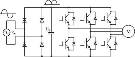
Fig.1 Topology of the EL-cap-less STI with front-end diode rectifier
(3)PF can be improved by some proposed control method[6-8,18-20].
Whereas,some disadvantages also exist:DClink voltage contains large ripple,leading to lower voltage utilization,larger speed ripple and slower dynamic response;energy cannot feedback to the input source owning to the front-end diode rectifier,making it not suitable for applications requiring rapid load variation or braking.These characteristics limit its applications but donot hinder the possible using in some variable-frequency AC motor drivers for home electrical appliances,such as compressor of air conditioner,since neither the rapid dynamic response nor the braking is needed in these systems.Therefore,it has the chance to replace EL capacitors with film-type capacitors.
The goal of this paper is to present capacitance chosen guideline of the film-type DC-link capacitor and harmonics injection method of STI with frontend diode rectifier,so that film-type capacitors can be employed to achieve a longer lifetime and higher system integration for motor drive system.Power factor calculation and DC-link capacitor estimation of STI with front-end diode rectifier are described in Section II.Control method of EL-cap-less STI based motor drive system is described in Section III.Finally,simulation and experimental results are included in Section IV.
1 Film-Type Capacitor of STI with Front-End Diode Rectifier
1.1 Input power factor calculation
Fig.2(a)shows the envelope lines of input voltage vin,DC-link voltage vband input current iinfor EL-cap-less STI.Due to a small amount of capacitance still exists,the valley of DC-link voltage is Vbmrather than zero.During the intervals of[0,( π-θ) 2)and(( π+θ) 2,π](θis the conduction width of diode rectifier),DC-link voltage reaches Vbm,so input current iin=0.During the interval of[( π-θ) 2,( π+θ) 2],input current iinchanges in a sinusoidal way.Therefore,input AC voltage and current across the line cycle can be expressed as

where Vmand Imare the magnitude of input voltage and current,andωinis the angular frequency of AC source,respectively.The input active power is derived as

The RMS of input current can be expressed as

Then the apparent power S can be derived as

PF can be calculated as

From the geometrical view of Fig.2(a),relationship between valley and peak of vbcan be derived as

where kbis the valley-to-peak ratio of DC-link voltage.From Eqs.(5)and(6),the relationship between PF and kbis shown in Fig.2(b),where kbis obviously related to PF.From Fig.2(b),the power factor is higher than 0.9 when kb≤0.7.

Fig.2 Relationship among voltages and currents,and relationship between PF and cos(θ/2)
The DC-link valley voltage can be reduced and the conduction widthθof the input current iincan be enlarged by using smaller DC-link capacitor,and therefore make iinmore sinusoidal and increase the PF.However,a certain amount of capacitance is still required to storage energy in the real system.This is because motor speed should be maintained during the DC-link valley voltage due to the moment of inertia,which induces the motor to run in the generation mode.The energy feedback to the DC-link should be smoothed during the DC-link valley voltage to prevent overshoot.The EL-cap-less STI is suitable for low and medium power application with slow speed dynamic response,especially for load with larger moment of inertia.
1.2 DC-link capacitance estimation
Assuming that the PF is of unity,the instantaneous input current can be expressed as

Then the instantaneous input power can be derived as

The average input power can be derived as

To control the PF to be high,output power unavoidably coupled with ripple components synchronous with line frequency.Supposing efficiency of the inverter is 100%,the input power of the inverter is equal to the apparent power of the motor

where the apparent power pMof the permanent magnet synchronous motor(PMSM)includes three parts:the dissipative power of stator resistance pR,the charge and discharge power of stator inductance pLand the electromagnetic power pem,where pR(t)=Lq)id(t)iq(t)],separately,in whichωeis the angular speed of rotor,Ψfis the rotor linkage flux,Ldand Lqare d-axis and q-axis inductances,idand iqare d-axis and q-axis rotor currents,and Rsis the stator resistance.Apparently,d-axis and q-axis rotor currents include ripple components fluctuating with twice line frequency.Therefore,pR(t),pL(t)and pem(t)are all synchronous with twice line frequency.Because the value of Rs,Ldand Lqare relatively small,the variation of pR(t)and pL(t)can be neglected.The apparent power of PMSM can be expressed as

The voltage equations of PMSM can be expressed as

where p is the differential operator.The power flows through DC-link capacitor Cbis

Here,pc(t)is determined by capacitance and amplitude of the input voltage,as indicated in Eq.(13).Key waveforms of the EL-cap-less STI when the PF is of unity are shown in Fig.3(a).When pin(t)>pinv(t),pc(t)>0,and vc(t)increases,Cbis charged;when pin(t)<pinv(t),pc(t)<0,and vc(t)decreases,Cbis discharged.
The energy charging Cbfrom 0 toπ/2 is

With Eqs.(8)and(10),ΔE also can be expressed as

From Eqs.(14)and(15),we can estimate DClink capacitance.To simplify the calculation further,pR(t)and pL(t)can be neglected because of much smaller effect of pR(t)and pL(t)compared with pem(t).Then theinput power of inverter equalsto the electromagnetic power of the motor pem(t).Because the inverter controller regulates the speed of the PMSM motor to be smooth,the ripple components of the motor torque exists.Then pinv(t)can be derived as

While the average value of pinv(t)can be derived as

where Tmis the magnitude of torque,andωmthe mechanical angular frequency.Supposing that the efficiency of inverter is 100%,the average power of input source Pinaveis equal to the average input power of inverter Pinvand also output power Po.Then peak value of torque Tmcan be expressed as

From Eq.(18),the magnitude of torque is related to the conduction widthθ.The largerθwould lead to higher PF and Tmfurther.
From Eqs.(14),(15)and(16),we have

Relationship between Tm,Cband the conduction widthθcan be illustrated by taking an EL-capless STI as an example.The output power Po=500 W,the magnitude and frequency of input voltage is 311 V and 50 Hz.From Fig.2(b),the relationship between PF and kbcan be found,that is PF≥0.9,when kb≤0.7.So substituting Eq.(6)into Eq.(18)yields

Then curves of Tmas a function ofωmcan be shown in Fig.3(b).Whenωmis about 1 000 rad/s and kb=0.7,the peak value of torque Tmis about 0.8 N·s.If kbis reduced to 0.3 and PF is about 0.99,Tmis about 1 Ns.The torque ripple is larger when PF is improved.From Eq.(19),curves of Cbas a function of kbcan be shown in Fig.3(c).When kb=0.7,Cbis about 10μF.The higher PF is,the smaller Cbis needed to maintain the conduction width of the diode rectifier.

Fig.3 Key waveforms of EL-cap-less STI;and T m as a function ofωm;and C b as a function of k b
2 Control Method of EL-Cap-Less STI Based Motor Drive System
The overall control block diagram of EL-capless STI is shown in Fig.4.The control method is a modified vector control suitable for EL-cap-less STI with improved PF.The speed controller output is the amplitude reference of q-axis current.The ripple components of d-axis and q-axis current reference are made in synchronous with the DC-link voltage to improve the PF.In addition,the real minimum value of the DC-link voltage is low when the desired PF is high as indicated in Fig.2(a).The voltage limiter is necessary for preventing over modulation.When the DC-link voltage varies during every line period,both d-axis and q-axis voltage which are the outputs of current loops cannot change rapidly due to the feedback control.Therefore,a voltage feedforward factor should be introduced into the current loops,to improve speed response of the feedback control during over-modulation correction and also prevent large errors of v′d,v′dand vd,vqfurther.
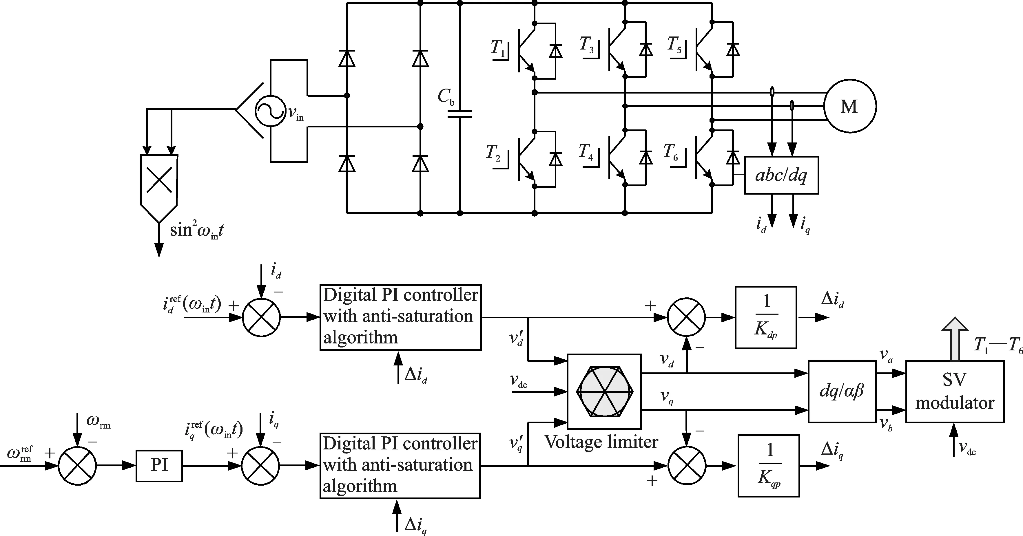
Fig.4 Overall control block diagram of EL-cap-less STI system
2.1 The d-axis curr ent controller
For the motor drive system,the flux-weakening-control method is applied in order to maintain the motor speed after DC-link voltage reaches its minimum value.According to the voltage constraint ellipse,d-axis current referencecan be expressed as

However,Eq.(21)is not suitable for the ELcap-less STI PMSM drive system[18].As mentioned above,d-axis and q-axis rotor currents are fluctuating.Therefore,the voltage constraint ellipse cannot be derived and the traditional flux-weakening-control method is not appropriate here.Because the DClink voltage couples with twice line frequency component,the effective voltage level is lower than that of constant voltage if keeping the same peak value.That means to reach the same required speed value,more d-axis flux-weakening current should be applied.And thefluctuation caused by DC-link voltage would aggravate the current regulation performance[18].should be expressed as follow in this system.

where Idofsis a negative offset component,Iripplethe magnitude of the harmonic component,andδthe deviation angle between input voltage and the harmonic component.These parameters are manually regulated to obtain high power factor under different operation conditions.
2.2 The q-axis curr ent controller
To obtain high PF,the DC-link voltage valley should be as low as possible.Low DC-link voltage valley would enlarge the conduction width of frontend diode rectifier and improve the input current quality.So the desirable polarity of q-axis current should be positive to prevent power feed back to the dc link,and this is realized by setting minimum value of q-axis current reference to zero.Though the controlled polarity of q-axis current reference is positive,the real q-axis current is slightly negative.This is caused by the electromotive force which would rise up the DC-link voltage valley under steady state.The q-axis current reference is given as

where Iqis the output of the speed regulator,andλ the deviation angle between input voltage and the ripple component.Andλis manually tuned to obtain high PF under different operation conditions.
2.3 Phase angle testing of input voltage
As mentioned above,the d-axis and q-axis current references have ripple components which are both synchronous with the input voltage.Therefore,phase angle of the input voltage should be obtained first.
For single-phase converter,coordinate transformation cannot be performed directly.It is necessary to reconstruct the coordinate transformation in single-phase input system.
Supposing that the arbitrary input voltage expression is as follow

whereψis the initial phase angle of the input voltage.Eq.(24)can be resolved into

where Vdin=Vm·cosψand Vqin=Vm·sinψ.The variation of Vdinand Vqinis small,so Vdinand Vqincan be treated as the dc component.A decoupling method is presented to decouple the dc component from Eq.(25).The control block diagram is shown in Fig.5,in which a low-pass filter is used to filter out the harmonics at the switching frequency first.

Fig.5 The d-q decoupling control block diagram in virtual stationary coordinate
Then a virtual two phase stationary coordinate is constructed by delaying 1/4 period of the actual input AC voltage.Finally,Vdinand Vqincan be obtained from park transformation[22-23].
The orthogonal signal which delaying 1/4 period of the actual input AC voltage can be expressed as

Then{vin(t),v′in(t)}constructs two-phase virtual orthogonal coordinate,αβ coordinate.And vin(t)and v′in(t)can be defined as

Vdinand Vqincan be obtained byαβ-dq coordinate transformation module to transform the AC voltages into DC values

Then the initial phase angle of the input voltage can be obtained as

The amplitude of the input voltage can also be obtained as

2.4 Anti-saturation current control loop
In the traditional vector control,the d-axis and q-axis current references are of constant DC values.Therefore,only two PI regulators are applied to the current controller to realize precise tracking of d-axis and q-axis current references.The outputs of the current controller,vdand vq,are limited by the voltage limiter to prevent over-modulation,and then input to the inverse park transformation block to generate driving signal of PMSM motor.The traditional current control block diagram is shown in Fig.6(a).
Different from traditional vector control,the daxis and q-axis currents are rippled with twice line frequency.This kind of current would lead to output saturation of the current PI controller if traditional current control method is used,and result in large harmonic components of the input AC current.The robust EL-cap-less STI drive system must prevent the output saturation of the current control loop.The anti-saturation current control block diagram is shown in Fig.6(b).The algorithm is based on the feedback control of saturation variablesΔidandΔiq.When the outputs of the current controller v′d,v′qare saturated,they are calculated again with outputs of the voltage limiter vlimdand vlimq,which can be expressed as

The integrators are corrected by the feedback ofΔidandΔiqwithin one sampling period,leading to rapid regulation.In next sampling period,the output of the current controller has already been corrected,so the anti-saturation current tracking control is achieved in one current sampling period and the input AC current waveform can be improved.

Fig.6 Current control block diagram
3 Simulation and Experimental Results
3.1 Simulation results
A simulation model of EL-cap-less STI has been constructed by using PLECS software.The dclink capacitor Cbis about 15μF.The motor parameters of PMSM are listed below:
(1)Stator winding resistance r1:0.495Ω;
(2)Stator d-axis inductance Ld:5.46 mH,qaxis inductance Lq:12.06 mH;
(3)Permanent magnet flux linkage Ψ:0.138 6 Wb;
(4)Inertia J:9.6×10⁻⁴kg·m2;
(5)Pole number:6.
Fig.7 shows the simulation waveforms under motor speed of 3 000 r/min.Fig.7(a)shows the input voltage and current,from which iinis almost in the same phase with vin,and conduction width is about 120°.Fig.7(b)shows harmonic components of iin.The amplitude of 3rd,5th,7th and 9th harmonic components are 0.7,0.165,0.3 and 0.34 A,separately.Fig.7(c)shows waveforms of d-axis and q-axis current.The current control loop with antisaturation algorithm can realize rapid tracking of the current reference injected with large ripple.The antisaturation algorithm corrects the output variables of current controller during the current sampling period,in the form of feed-forward saturation variables ΔidandΔiq.Fig.7(d)shows the waveform of the motor speed with its reference of 3 000 r/min.The speed ripple is very small,and the start-up is quick and without oscillation.
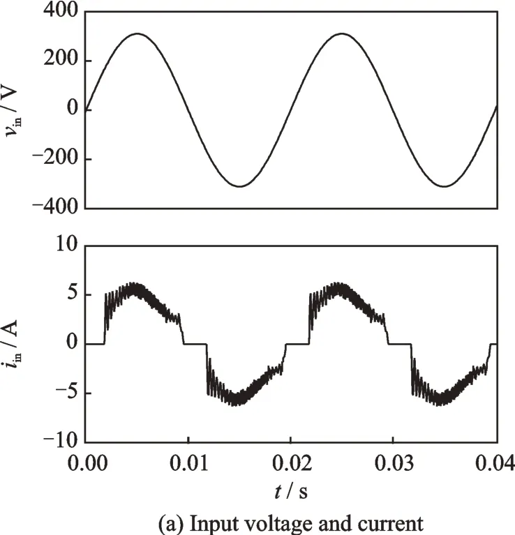

Fig.7 Simulation waveforms
3.2 Exper imental results
To verify the validity of the proposed methods,an EL-cap-less STI prototype,is constructed.The power devices and components of the EL-capless STIare listed as follows:
(1)DC-link capacitor:15μF metalized polypropylene film capacitor;
(2)Power devices:IPM module PS21A 79.

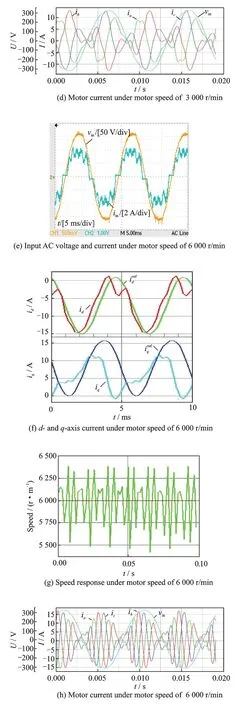

Fig.8 Experimental results
Fig.8 shows key experimental waveforms with an air conditioning compressor as the load.The motor parameters of the tested PMSM are the same as those in the simulation part.The input AC voltage is set to 220 Vrms/50 Hz.The switching frequency is 10 kHz.Figs.8(a)—(h)show experimental waveforms under motor speed of 3 000 r/min and 6 000 r/min.Figs.8(a)and(e)show waveforms of input AC voltage and current,where iinis almost in the same phase with vin,while the sinusoidal waveform is not good enough and has harmonic components.The tested PF is 0.95 and can meet the relative standard.The PF is improved to 0.98 under 6 000 r/min.In case of film-type DC-link capacitor system,especially in single phase system,it is hard to achieve the satisfactory of the current regulation performance because of lack of voltage margin and digital delays.Figs.8(b)and(f)show experimental waveforms of d-and q-axis current.Larger negative d-axis current reference for flux-weakening is applied in order to raise the motor speed.The q-axis current reference is a fluctuating waveform formed by the output of speed regulator and the grid phase angle.Figs.8(c)and(g)show the experimental waveform of the speed response,whose errors are lower than±9%.The motor currents are shown in Figs.8(d)and(h),whose envelope is synchronized with the input AC voltage.Fig.8(i)presents the input power factor comparison under different input power.The PF value increases as the input power increases,and reaches its highest value under motor speed of 6 000 r/min.Table 1 shows the comparison results of harmonics and standard IEC61000-3-2 Class A of input current under different motor speeds.Therefore,the ripple components of input current can meet the standard.The efficiency of EL-cap-less STI system is 85.6%at the rated speed of 6 000 r/min,and that of the structure shown in Fig.1 with aluminum electrolytic capacitor is 89%under the same condition.
4 Conclusions
This paper proposes an EL-cap-less STI system featured with simple structure,improved reliability and high PF.In the system,the DC-link storage capacitance can be significantly reduced so that film-type capacitors can be used instead of electrolytic capacitors.The capacitance choosing guideline of the film-type capacitor is presented.To achieve high PF,harmonics synchronized with the DC-link volt-age are injected into the d-and q-axis current controllers.To prevent saturation of the current controller output,anti-saturation current tracking control is employed.Simulation model and laboratory prototype are built,and steady-state performances are tested to show its validity.
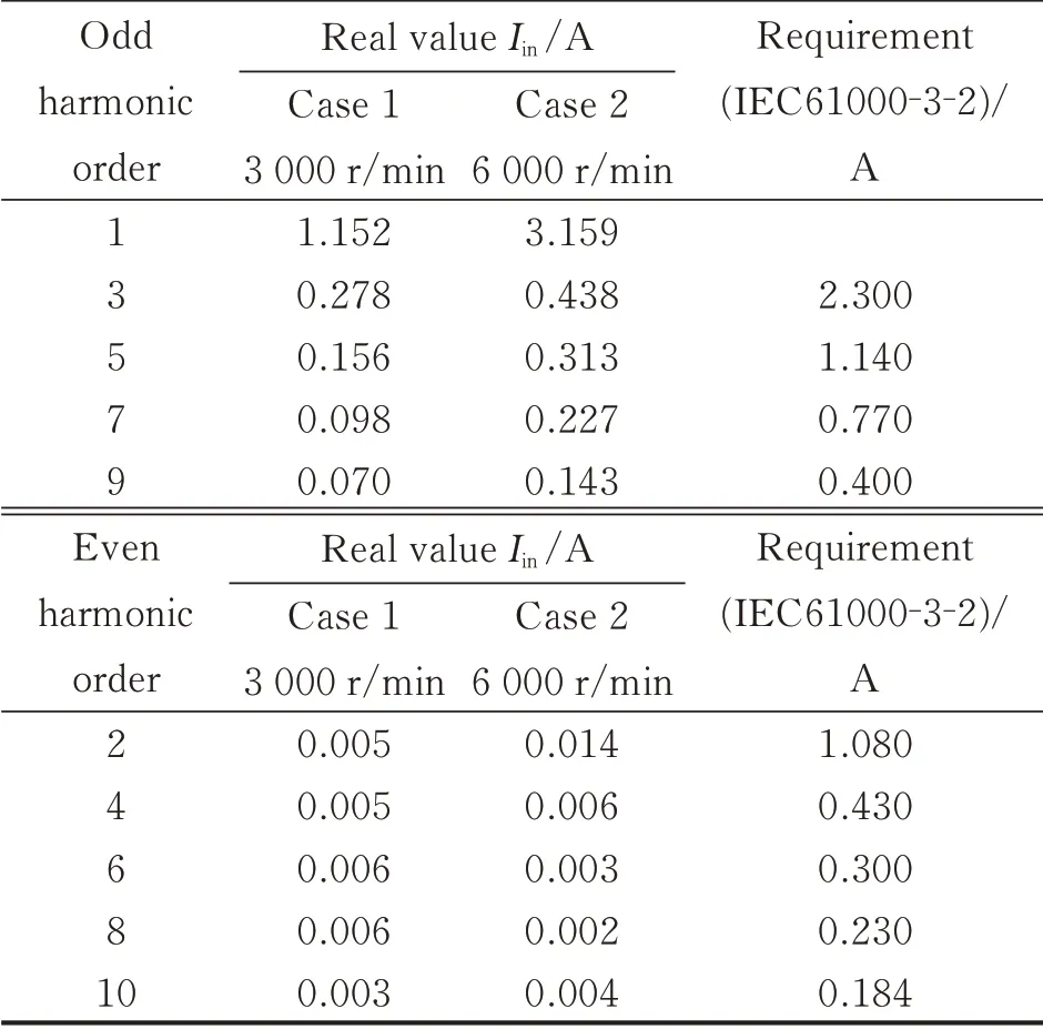
Table 1 Har monics v.s.standar d IEC61000-3-2 Class A under different motor speed
杂志排行
Transactions of Nanjing University of Aeronautics and Astronautics的其它文章
- BeiDou B1I/B3I Signals Joint Tracking Algorithm Based on Kalman Filter
- Impact Analysis of Solar Irradiance Change on Precision Orbit Determination of Navigation Satellites
- Characterization of Self-driven Cascode-Configuration Synchronous Rectifiers
- Cooperative Search of UAV Swarm Based on Ant Colony Optimization with Artificial Potential Field
- H∞Preview Control for Automatic Carrier Landing
- Analysis of Flight Dynamics Characteristics of Tilt Quad Rotor with Partial Tilt-Wing
