A Laser Line Scanner Based Hole Position Correction Mechanism for Automatic Drilling and Riveting in Aircraft Assembly
2019-03-07ZHANGLinTIANWeiSUNHailongXUEQiweiLIUYangyangLIAOWenhe
ZHANG Lin,TIAN Wei,SUN Hailong,XUE Qiwei,LIU Yangyang,LIAO Wenhe
1.College of Mechanical&Electrical Engineering,Nanjing University of Aeronautics and Astronautics,Nanjing 210016,P.R.China;
2.Laboratory of Aeronautics Intelligent Equipment Technology Research,AVIC Chengdu Aircraft Industry(Group)Co.,Ltd.,Chengdu 610092,P.R.China;
3.School of Mechanical Engineering,Nanjing University of Science and Technology,Nanjing 210094,P.R.China
Abstract:The low-stiffness of aircraft skins may results in the differences between aircraft actual parts and their theoretical models,which will consequently affect the accuracy of automatic drilling and riveting in aircraft assembly.In this paper,a novel approach of hole position correction using laser line scanner(LLS)is proposed to assign a single row of holes on the parts’surfaces.First,we adopt a space circle fitting method and the random sample consensus(RANSAC)to obtain the precise coordinates of center of the datum holes’coordinates.Second,LLS is calibrated by the laser tracker,and the relations between the LLS coordinate system and the tool coordinate system(TCS)can be calculated.Third,the kinematics model of the automatic riveting machine is established based on a two-point referencing strategy proposed in this paper.T hus,the positions of the holes to be drilled can be adjusted.Finally,the experimental results show that in TCS the measurement error of LLS is less than 0.1 mm,and the correction error of the hole position is less than 0.5 mm,which demonstrates the reliability of our method.
Key words:aircraft assembly;automatic drilling and riveting system(ADRS);laser line scanner(LLS);position correction
0 Introduction
Assembly automation has been progressing in aerospace industry for nearly a decade.Driven by commercial requirements,airspace automation has primarily counted on automated drilling and riveting machines to reduce cost and improve quality,which has hence boosted the advancement of automatic drilling and riveting systems(ADRSs).For example,the leading aerospace automation company,ELECTROIMPACT,has customized a robotic drilling system for Airbus[1],and its archrival,BROETJE-Automation,has developed a mobile robot based drilling and fastening system for multi uses in aircraft assembly automation[2].Despite the efficiency ADRSs are brought out,a critical problem remains the drilling process.Modern aircraft skins coming to assembly usually hold a low stiffness,and their shapes might differ from their theoretical models forged by computer aided design(CAD)[3].Positioning holes to be drilled on those materials inevitably lead to deviations.Typically,two terms are used to describe these variations:position error,referring to the deviation between the coordinates of a hole in theoretical models and those in actual parts;and orientation error,regarding the difference between the normal vector of a part’s surface and the spindle axis of the tool.
Researchers have adopted different approaches to address this issue,including laser range sensors[4-5],monocular vision and stereo cameras.Shi et al.[6]designed an intelligent normal adjustment cell for hole-drilling end effectors by using a double-eccentric disk normal adjustment mechanism and a spherical plain bearing.Although their approach was proved capable of improving hole-drilling quality,it could achieve an adjustment only within±5°and is too complicated to be installed on certain existing end effectors.Yu et al.[7]deployed four laser displacement sensors to measure surface normal errors in a fast and simple way,but without considering position errors.Zhu et al.[8-10]developed a 2D vision system for hole-positioning accuracy and investigated the principles of error measurement and error compensation for robotic drilling.Their research demonstrated that measurement accuracy could be enhanced if both the perpendicularity of the camera optical axis to the workpiece surface and the object distance are properly maintained during the measurement process,albeit in a time-consuming way.Wang et al.[11]utilized the visual measurement system to detect and correct installation error between workpiece and the robot drilling system,and devised an effective approach of calibrating an base detection.
More than measurement systems,many studies have devoted to reference strategies.Zhu et al.[12]used bilinear interpolation models to correct the hole position according to measurement data of reference holes.Sumeihl et al.[13]discussed different optical reference strategies,including the three-point geometric strategy,the multi-point geometric strategy,the multi-point best-fit strategy and the static helper-frame strategy.
In this paper,a novel approach was proposed to measure datum holes for the ADRS.In Section 1 the architecture of the ADRS was briefly described.Then,Section 2 presented the measurement system with LLS.The calibration method of LLS was described in Section 3.The referencing strategy was introduced in Section 4.The experiments were introduced,and some results were shown in Section 5.
1 Automatic Drilling and Riveting System
A functional ADRS consists of five components:a five-axis machine tool,a MFEE,ground rails,a rotary table and an aircraft part,as shown in Fig.1(a)[14].The part is fixed on a rotary table,which can spin around 360°.The five-axis machine tool moves along the linear ground rails.The independently developed MFEE is installed on the ram of the machine tool and can approach the part from all directions.
MFEE,the essence of ADRS,involves several modules,as shown in Fig.1(b),to complete different functions,like clamping pressure foot,drilling holes,feeding nails,riveting,etc.All these processes are controlled by a programmable logic controller(PLC).MFEE also incorporates different sensors,like laser displacement sensors,a laser line scanner(LLS),length gauges and electromagnetic proximity sensors,to guide those processes.For example,the four laser displacement sensors measure surface-normal of the part and adjust MFEE to be perpendicular to the surface of the part for hole-drilling.
The whole system is operated through dedicated software,and follows a workflow that includes two critical tasks:measurement and correction.
(1)Numerical control(NC)codes,generated by off-line program based on the CAD model,are input into the control software.
(2)The machine tool drives MFEE to the position of the datum hole.
(3)LLS scans the pre-drilling datum hole and obtains its coordinates.
(4)The actual drilling position is calculated by using the deviation between the coordinates of the datum hole in CAD model and those that LLS obtains in(3).
(5)The machine tool drives MFEE to the calculated drilling position.

Fig.1 Automatic drilling and riveting system
(6)MFEE performs drilling and riveting.
2 Measurement
2.1 Mechanism for scanning the datum hole
Fig.2 explains the mechanism of scanning the datum hole.A LLS is mounted on a high-precision linear guide and driven by a servo motor.The LLS measures range and direction to reflect the surface of an object with high precision.The data it gleans are transformed into the sensor coordinate system(SCS),that is,Y and Z coordinates,while the value on X axis is the distance the LLS travels along the linear guide,which can be read through the motor controller.Thus,the 3D surface of the part can be plotted through measurement.
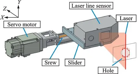
Fig.2 Mechanism for scanning the datum hole
Table 1 lists LLS’s key parameters.The measuring range of the LLS is within a square of 25 mm×25 mm,and the servo motor moves within a length of 25 mm.The datum hole usually holds a diameter of 3—4 mm,which falls within the measuring range given the assembly error less than 10 mm.The LLS bears a resolution of 2μm on both Y and Z directions,and the motor has a 1μm resolution on X direction,which results in a synthetic resolution of=3μm,catering to the measurement demand.
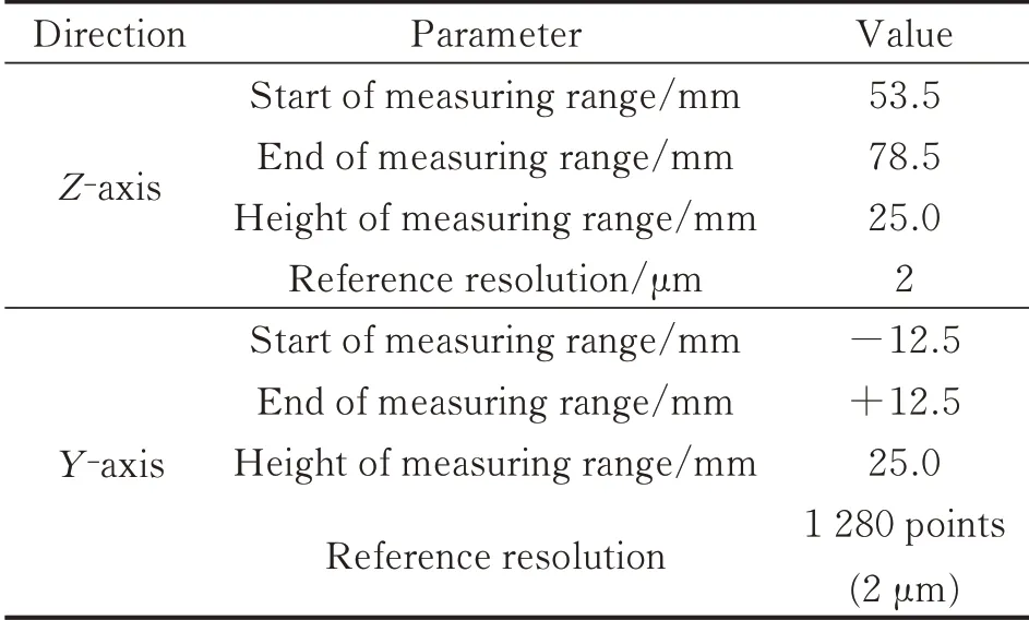
Table 1 Parameters of the laser line scanner
2.2 Circle fitting algor ithm
2.2.1 Obtaining edge points
The LLS obtains 1 280 points to describe a profile.Fig.3 shows the coordinates of all the points of a profile,where the two edge points can be clearly identified.In order to obtain the two points,we adopt a point-by-point comparison method.

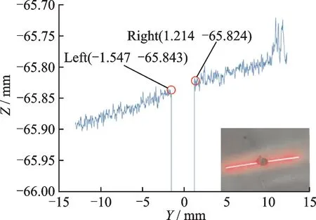
Fig.3 Coordinates of the 1 280 points of a prof ile
where i is the index from 1 to 1 280 andεthe threshold for comparison.Eq.(1)implies that the left edge point is the one whose Z coordinate is almost the same as that of its immediate predecessor,but much larger than that of its immediate successor;while the right edge point follows a complete opposite rule.If the laser line misses the hole,there is no edge point.
2.2.2 Plane fitting
As the motor is moving,a series of points can be obtained and regarded as locating on the circumference of the hole.A hole with a diameter of 4 mm might provide about 50 points.The circle fitting algorithm was used to calculate its center.
Suppose there is a set of points P{p1,p2,…,pn},where all the points are on a same plane denoted asπ.Each point Piin P satisfies

where(xi,yi,zi) represent the coordinates of point Pi,and(a,b,c)the normal ofπ,which can determine a plane.
If P includes n points there are n equations like Eq.(2)and they can be unified as


Then N can be normalized by Eq.(5)

2.2.3 Project of the point set onto the plane
Since no equation is available to describe a circle in 3D space,we have to fit the scanned points into a 2D circle to find the hole center.Therefore,we can project the points in set P onto planeπ,and the projected points compose a setFig.4 displays the projection results,where the solid dots represent the points in P,and the hollow dots represent the projected points.
Denote the distance between piand p′ias di.
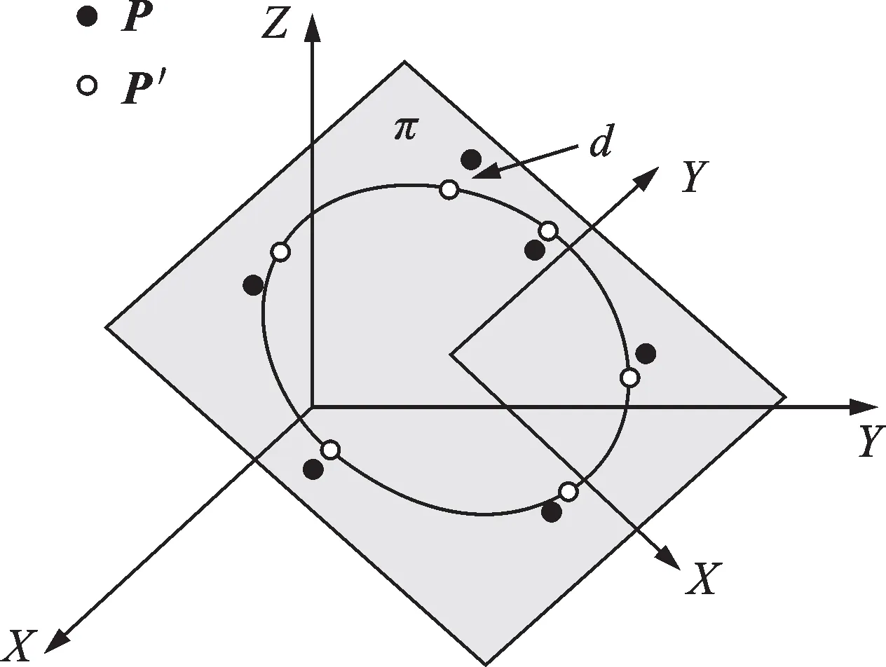
Fig.4 Projection of scanned points onto planeπ
Then p′i(x′i,y′i,z′i)can be expressed as

Since p′iis just on the planeπ,it satisfies the Eq.(2).Thus,substituting p′iinto Eq.(2),we have

Therefore,dican be obtained

Then,substitute diinto Eq.(6),we can obtain p′i(x′i,y′i,z′i).
2.2.4 Transformation of a 3D circle into a 2D circle
Assume that Q{q1,q2…qn}is a set of points on the plane xoy,Q can be transformed into P′through two steps:Q first rotates around the X axis and then rotates around the Y axis,that is

The transformation matrix from Q to P′is
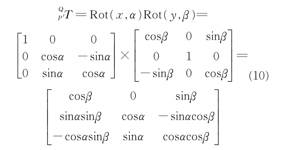
Since the normal of planeπ is(an,bn,cn),Eq.(11)is obtained

Thus

Substitutingαandβinto Eq.(9)and Eq.(10),we can obtainand Q.
2.2.5 2D circle fitting
The equation of 2D circle is expressed as

Since point qi(x″i,y″i,0)satisfies Eq.(13),and is included in set Q,we have

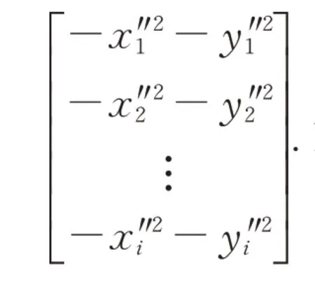

Then,the center of the 2D circle outlined by points in set Q is

And its radius is

The center of the 3D circle delineated by points in set P is denoted as O(xo,yo,zo),and O can be calculated as

Thus,center and radius of the 3D circle are obtained by coordinate transformation and the fitting algorithm.
2.3 RANSAC method
Section 2.2 describes an ideal situation where the circle fitting algorithm could perform.In the real world,not all the points in set P fall exactly on the circumference of the hole,given the burrs and scratches that often emerge on the surface.The outliers may severely interfere the results of fitting.Therefore,we adopt random sample consensus(RANSAC)to filter the outliers.The filtering steps are as follows.
(1)Randomly select 4—5 points from the original point set P to compose a subset called the hypothetical inliers H.
(2)Fit a 3D circle of the points in H by using the method described in Section 2.2.The resulted model includes a circle with a center of,and a radius of rh,and a planeπh.
(3)Calculate the key parameters revealing relative positions between the model and each of the rest points in P through Eq.(19)

where Rirepresents the distance between point pito the center of the circle and Dithe distance between piand planeπh.
(4)Determine whether the rest points fit the estimated model by

where Rtis the threshold in radial direction,and Dtthe threshold in normal direction ofπh.If a point satisfies Eq.(20),it is included into the consensus set.
(5)If sufficient points are included in the consensus set,say 80%of the rest in P,the fitted model is regarded as reasonably good and the filtering proceeds to the next step;otherwise,it goes back to(1)and starts with reselecting H.
(6)Improve the fitted model by re-estimating it using all the points in the consensus set.
3 Sensor Calibrations
3.1 Establishment of tool coordinate system
Tool coordinate system(TCS),denoted by$Tool,is convenient for numerical control to determine the machine’s positions and attitudes.We introduce a laser tracker with an accuracy of 0.025 mm to establish a TCS.The target ball of the laser tracker is mounted on the tool holder of the spindle through a fixture,as shown in Fig.5.
Thus,the origin of the TCS is the center of the target ball,which is 10 mm away from the press foot plane.The TCS consists of the Z-axis that is along the feed direction of the spindle,the vertical Y-axis and the horizontal X-axis.This definition of TCS is close to that of the machine coordinate system(MCS),which will benefit numerical control.
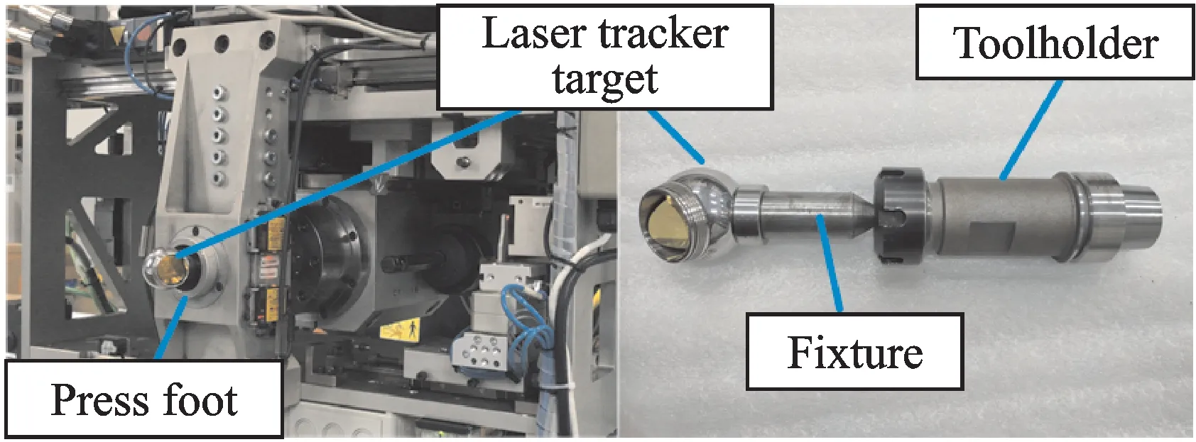
Fig.5 Installation of the target ball of the laser tracker
Fig.6 explains the TCS,where the red dots are those measured by the laser tracker.The establishment of TCS is as follows.
(1)Stick the target ball onto the surface of press foot and move it,thus the laser tracker could measure a series of points.Use these points to fit a plane,and denote it asπP.
(2)Fix the target ball on the spindle.Adjust the feed motor by using the laser tracker to ensure the 10 mm distance between the center of the target ball and planeπP.Then set the center of the target ball as the origin of TCS.
(3)Move the machine tool along the X-axis of MCS,and the laser tracker captures the trajectory of the center of the target ball,that is,a straight line denoted as lx.
(4)Move the machine tool along the Y-axis of MCS,and the laser tracker measures the trajectory of the center of the target ball,ly.
(5)Define the line passing through the origin and parallel to lxas the X-axis of TCS,and the line perpendicular to the plane where lxand lycross as the Z-axis.Thus the Y-axis is defined by the right-hand rule.
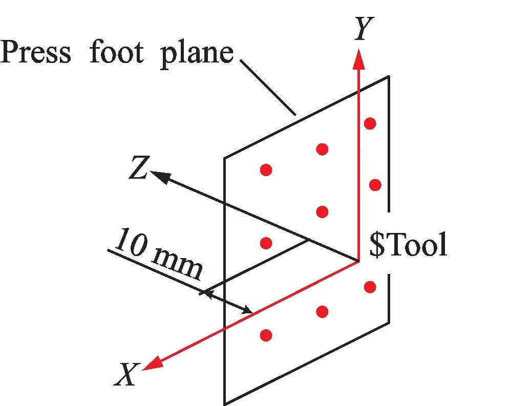
Fig.6 T ool coordinate system
3.2 Calibration pr ocess
The points scanned by LLS are endowed with the coordinates on the sensor coordinate system(SCS),denoted as$Sensor,which have to be transformed to those on the TCS.But the exact position of LLS cannot be determined in advance given the installation error.Therefore,the transformation must be precisely calibrated

There is a fixed calibration board with a smooth hole,as depicted in Fig.7.
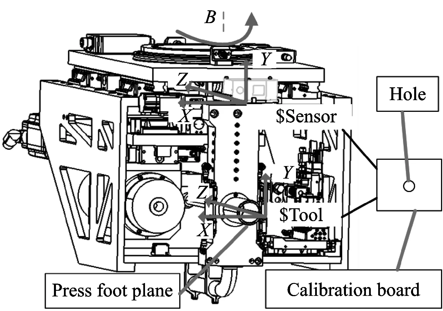
Fig.7 Sensor calibration
The hole is within the measurement range of LLS.Thus,the SCS coordinates of the hole,denoted as ps,can be obtained by the method described in Section 2.3,while the TCS coordinates of it,denoted as pt,can be measured by the laser tracker.After several experiments,two point setsandcan be obtained,whereold the following relation

(1)Calculate the average of Psand Pt
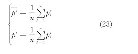

(3)Calculate the 3×3 matrix H

(4)Find the SVD of H


Therefore,the transformation between the two systems can be described as assume that the datum hole measured by LLS in TCS,and can be expressed as

where(Os,ns)is the SCS coordinate pair of the position and the orientation of a hole,and(Ot,nt)its counterpart in TCS.
4 Referencing Strategy
4.1 Kinematic model
Fig.8 explains the structure of the five-axis machine tool.It consists of three linear axes X,Y and Z,and two rotary axes A and B,which rotate about the X-axis and the Y-axis,respectively.
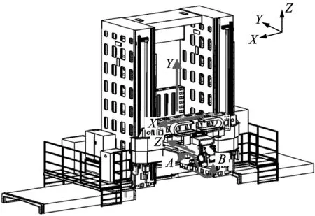
Fig.8 Structure of the machine tool
The MCS,denoted as$Base,is a base coordinate system fixed to the machine tool body,as outlined in Fig.9.The three lines in Fig.9,rotary centerline of the A-axis,rotary centerline of the B-axis,and feed line of the spindle,can be measured by the laser tracker.Initially,the three lines are perpendicular to each other,and the coordinate system composed of the X-axis,the Y-axis,the Z-axis and the A-axis is coincident with the MCS.In Fig.9,l1denotes the distance between the two rotary centers of A-axis and B-axis,and l2,l3and l4are annotated as well.The transfer chain of machine tool is as[15]:$Base→$X→$Y→$Z→$A→$B→$Tool.
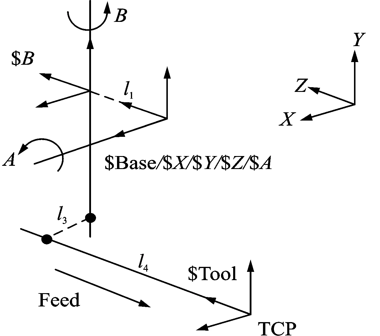
Fig.9 Coordinate systems of the machine tool
According to the rigid body model,relation between the MCS and the TCS can be modeled as

wher e
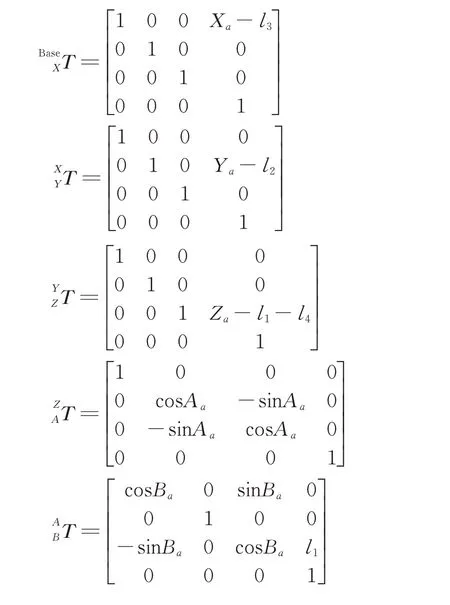
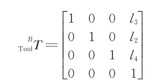
The third column of the matrixidentifies the Z-axis of TCS relative to MCS.The forth column identifies the origin of TCS,which is also tool tip point(TCP).Assume that(xg,yg,zg,ig,jg,kg)is the position and the direction of the tool tip in MCS,we have
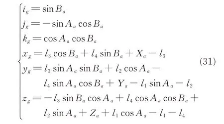
Solving Eq.(31),we can obtain the inverse kinematics as
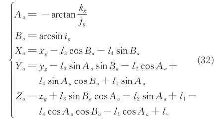

Given the TCS coordinates(Ot,nt),the position and the orientation of the datum hole measured by LLS,the position and the orientation of any hole,denoted by(Ra,na),in MCS can be calculated as

4.2 Two-point strategy
A group of rivets that fasten an aircraft part and the frame together might be roughly distributed along a straight line,usually following a narrow stringer.But given the assembly errors,the theoretical positions of the holes might deviate from the stringer.Therefore,holes at both ends of the line are used as datum,which will be drilled in advance,and others will be adjusted according to the datum holes.
Fig.10 presents the referencing strategy,including translating,rotating,and scaling transformation between theoretical and actual parts,where the solid black spots represent the datum holes,and the hollow circles represent the holes need to be drilled.
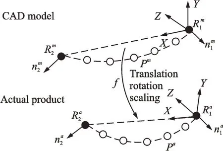
Fig.10 Principle of referencing strategy
By establishing local coordinate system(LCS),mapping between the theoretical model and the actual part can be created.The LCS can be established through two datum holes.Its origin and the base vectors can be described as
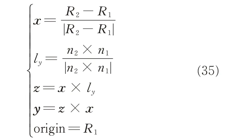
where Ridenotes coordinates of a datum hole,and nithe orientation of a datum hole.The LCS’s origin is on R1and its X-axis is coincident with R1R2.Cross-product n2×n1is nearly parallel to Y-axis.
The LCS can be established in both CAD model(denoted as$Model)and on the actual part(denoted as$Real).If the theoretical positions of the holes to be drilled in the CAD model are set as Pm,their LCS-$Model coordinates Lmcan be calculated as

The scaling factor between two LCSs can be defined as

Then the LCS-$Real coordinates are

Thus the corrected drilling position Pais obtained as

Adjusting the normal vector before drilling does not change the orientation of the holes to be drilled,and they remain the theoretical values,that is

Finally,on base of inverse kinematics,the joint coordinates of machine tools can be determined.
Fig.11 elaborates the whole procedure of referencing.
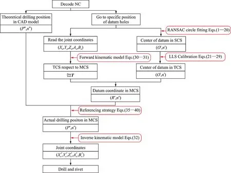
Fig.11 Procedure of referencing
5 Experiments and Verification
5.1 Measuring accuracy
In order to verify the accuracy of the measurement system we established an experimental platform,as shown in Fig.12.The platform consists of ADRS,a test piece on which holes had been drilled,and the Leica laser tracker.

Second,we established the TCS by using the method presented in Section 3.1.The datum hole was placed within the measuring range of LLS.
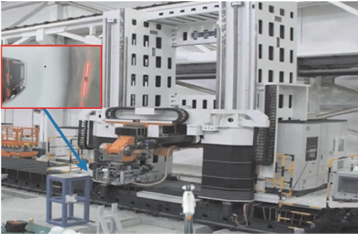
Fig.12 T he experiment platform
Then,we could obtain the hole’s TCS coordinates by TTL,and measured them by the laser trackers as well.By moving the hole,we could collect several measured results,as listed in Table 2,and the results demonstrated that the error in TCS of the measurement system is within 0.1 mm.This high accuracy accounts on the accuracy of LLS,the algorithm of circle fitting,and the calibration process.
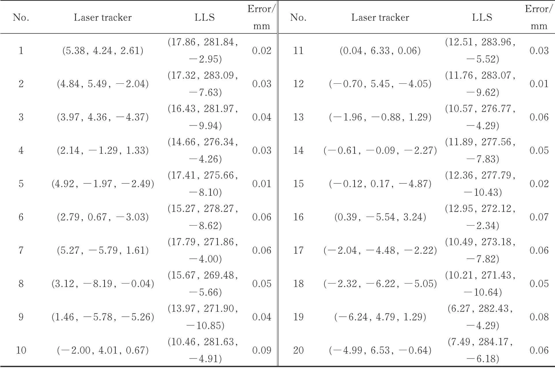
Table 2 Accuracy of normal measurement
5.2 Referencing accur acy
In order to verify the referencing strategy,we employed a cylindrical part that was similar to an aircraft fuselage,as shown in Fig.13.Its diameter was about 400 mm and its height about 1 500 mm.The datum holes had been drilled in both horizontal and vertical directions,and a series of theoretical positions,generated by offline programming,were evenly distributed between them.Based on these datum holes,the positions of holes to be drilled would be adjusted.
As shown in Fig.14,two criteria were adopted to verify drilling accuracy:the normal error en,indicating the distance from the actual drilling hole to the line determined by the two datum holes,and the lengthwise error eldefined as
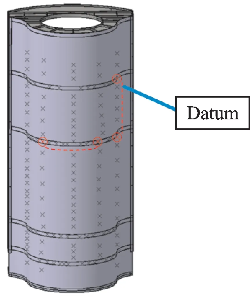
Fig.13 Experiment part

where diis the distance between two adjacent holes.
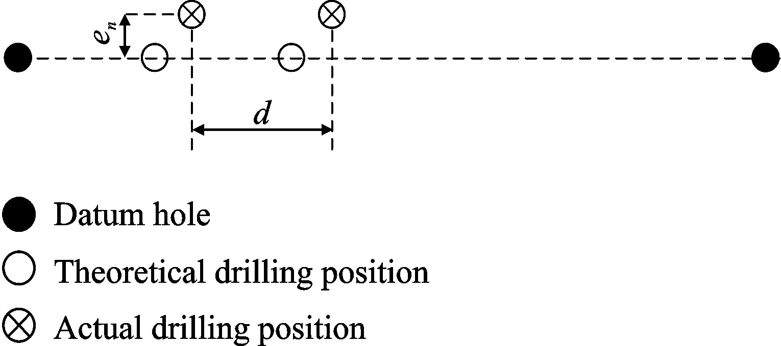
Fig.14 Diagram of precision criteria
Table 3 and Table 4 show the accuracy of a group of holes in horizontal and vertical directions,respectively.It can be seen that the error is less than 0.5 mm,and the errors of holes in horizontal direction is larger than that in vertical direction,because the curvature of product in horizontal direction is larger than that in the vertical direction.
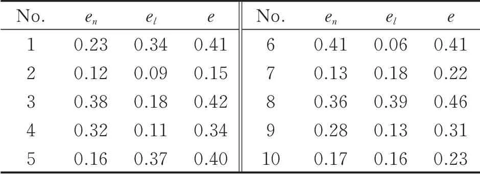
Table 3 Refer encing accur acy of holes in horizontal direction mm
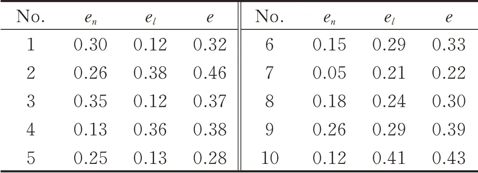
Table 4 Referencing accuracy of holes in vertical direction mm
6 Conclusions
This paper presents a measuring mechanism that consists of a LLS and a servomotor for the ADRS in aircraft assembly.First,we adopt a RANSAC fitting algorithm to obtain the centers of the holes in 3D space,and devise a method to calibrate LLS.Second,we establish the kinematic model of the machine tool,and clarify the relation between the TCS and the MCS,thus the coordinates of the datum holes in MCS can be measured.Third,we design a two-point referencing strategy to finally adjust the positions of the holes to be drilled.
We also establish an experimental platform to validate our approach.The experimental results indicate that the accuracy of the measuring mechanism is less than 0.2 mm,and the referencing accuracy of the holes after correction is less than 0.5 mm.
We intend to improve the accuracy of our approach,by calibrating the machine tool and collecting more accurate parameters.Also,we would expand the scope of LLS from holes to datum rivets.
杂志排行
Transactions of Nanjing University of Aeronautics and Astronautics的其它文章
- BeiDou B1I/B3I Signals Joint Tracking Algorithm Based on Kalman Filter
- Impact Analysis of Solar Irradiance Change on Precision Orbit Determination of Navigation Satellites
- Characterization of Self-driven Cascode-Configuration Synchronous Rectifiers
- Cooperative Search of UAV Swarm Based on Ant Colony Optimization with Artificial Potential Field
- H∞Preview Control for Automatic Carrier Landing
- Single-Phase to Three-Phase Inverter with Small DC-Link Capacitor for Motor Drive System
