Analysis of Flight Dynamics Characteristics of Tilt Quad Rotor with Partial Tilt-Wing
2019-03-07WANGZhigangDUANDengyanYANGYongwenYUHongruiLIJianbo
WANG Zhigang,DUAN Dengyan,YANG Yongw en,YU Hongrui,LIJianbo*
1.National Key Laboratory of Science and Technology on Rotorcraft Aerodynamic,College of Aerospace Engineering,Nanjing University of Aeronautics and Astronautics,Nanjing 210016,P.R.China;
2.Yangzhou Collaborative Innovation Research Institute,Shenyang Aircraft Design&Research Institute,Yangzhou 225000,P.R.China
Abstract:The aerodynamic model of propeller,wing,fuselage and vertical tail are established for the tilt quad rotor(TQR)with partial tilt-wing,and then the flight dynamic model is established.Based on the six-degree-of-freedom equation and the small disturbance linearization assumption,the trimming and stability of the tilt quad rotor with partial tilt-wing and the tilt quad rotor without tilt-wing are analyzed.The results show that in the hovering state,due to the existence of tilt-wing,the propeller wake reduces the downwash on the wing,thereby reducing the vertical weight gain of the aircraft.It is beneficial to increase the endurance time and improve the endurance performance.The transition corridor of the TQR with tilt-wing is narrower than that of the TQR without tilt-wing,but the transition corridor of TQR with tilt-wing still has a large space for design.Furthermore,the stability analysis shows that the Dutch roll damping ratio is larger,and in other modes the aircraft has a certain stability.The manipulation response analysis shows that in the transition mode the lateral-directional coupling is strong.
Key words:dynamics characteristics;tilt quad rotor;stability;manipulation response
0 Introduction
Tilt rotor aircraft has the advantages of both helicopter and fixed wing,as well as hovering,vertical takeoff/landing performance and high-speed forward flight ability[1-5].It has broad application prospects in both military and civilian applications.Since these new vehicles have no conventional design,many research groups build their own tilt rotor vehicles according to their desired technical properties and objectives[6-8].Others mainly reflected in the development of a general mathematical simulation model for tilt rotor aircraft flight dynamics to determine its transition corridor,but the model accuracy is not high,without considering the aerodynamic interference between the rotor and wing[9].Furthermore,flight tests had been conducted to obtain the transfer function of the corresponding channel by means of identification.It improves the model accuracy at high cost[10-12].Other research mainly focuses on the establishment of rotor and wing aerodynamic interference model[13-15],calculation of tilting transition corridor,control strategy of transition state and trimming method[16-18].
All the aforementioned studies focus on the general tilt rotor.The tilt rotor aircraft has the problem of rotor and wing aerodynamic interference.In a hovering state,the downwash of the rotor hits the wing directly,thereby leading to excessive energy consumption in the hovering state.The hovering state is one of the main working states of the tilt rotor aircraft.The flight time of the tilt rotor without the the tilt-wing is shortened.To solve the problem,we design a tilt rotor with partial tilt-wing,which reduces the downwash of the rotor to the wing in the hovering state.
The aerodynamic models of propeller,wing,fuselage and vertical tail are established first,and then the flight dynamic model of the aircraft.According to the six degrees of freedom equation and the small disturbance linearization hypothesis,the trimming,stability analysis manipulation response analysis,and coupling characteristics of the tilt quad rotor with and without tilt-wing are completed.It provides the technical basis for designing the automatic control system of the tilt quad rotor.
1 Aerodynamic Model
The tilt quad rotor with tilt-wing is shown in Fig.1,including four groups of propellers,front and rear wings,fuselage,elevator,motors,transmission mechanism,tilting mechanism,undercarriage,and flight control equipment etc.The parameters of the tilt quad rotor with tilt-wing is listed in Table 1.
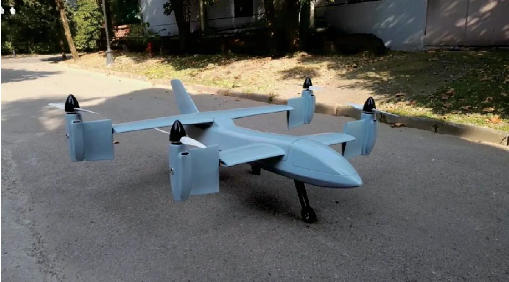
Fig.1 Tilt quad rotor with tilt-wing
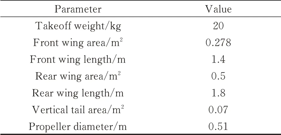
Table 1 Par ameters of the tilt quad rotor with tilt-wing
Both ends of the front and rear wings are designed with a tilt nacelle.The tilt-wing is connected to the tilt nacelle and turns with the tilt of the propeller in the nacelle.Hovering state is shown in Fig.2(a)and cruising state is shown in Fig.2(b).

Fig.2 Tilt quad rotor with tilt-wing
1.1 Propeller aerodynamic model
Compared with the conventional electric aircraft,the small electric tilt quad rotor has a smaller inflow ratio and a larger impeller load when it is hovering.The tilt quad rotor has a larger inflow ratio and a smaller impeller load when flying forward.
The propeller is modeled according to the Goldstein vortex theory.Fig.3 shows the velocity and force acting on the blade element,where R(m)is the radius,r the distance from hub center to any point of propeller profile,x the dimensionless value of r,σthe propeller solidity,ωthe rotational speed of the propeller,V the inflow velocity,λthe inflow ratio,φthe blade element angle,φTthe blade element inflow angle at propeller tip,αithe interference angle,VEthe resultant velocity,andωa,ωtthe axial circumferential induced velocity.

Fig.3 Velocity and force acting on the blade element

where B is the number of blades,Γthe blade element circulation,andκthe coefficient of Goldstein.

Thrust coefficient CT,power coefficient CPcan be calculated from Eqs.(4),(5).CLand CDare the lift coefficient and drag coefficient,respectively.
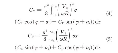
The thrust T and moment M can be calculated from Eq.(6),whereΩis the propeller rotational speed,ρthe atmospheric density,and D the diameter of propeller.

According to Eqs.(7),(8),the force and moment of the hub system are converted to the propeller system.
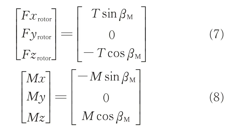
whereβMis the tilt angle.In addition,since the nacelle has a certain height,the position of the propeller in the transition mode is shown in Eq.(9).

where h is the distance of the propeller from the center of the nacelle.
The moment caused by the propeller in the body axis system is shown in Eq.(10).

To facilitate the calculation of the propeller wake at the wing,the average induced velocity of the propeller can be calculated by the slip flow theory according to Eq.(11).

1.2 Wing aerodynamic model
Due to the presence of the propeller,the area of the wing will be disturbed by the propeller wake.Considering that the tilt-wing of the small tilt quad rotor will turn with the nacelle,here we record that the tilt-wing turns with the nacelle as the slip flow area,and the wing does not turn with the nacelle as the free flow area.The aerodynamic model of the wing is built by taking the left part of the wing as an example.
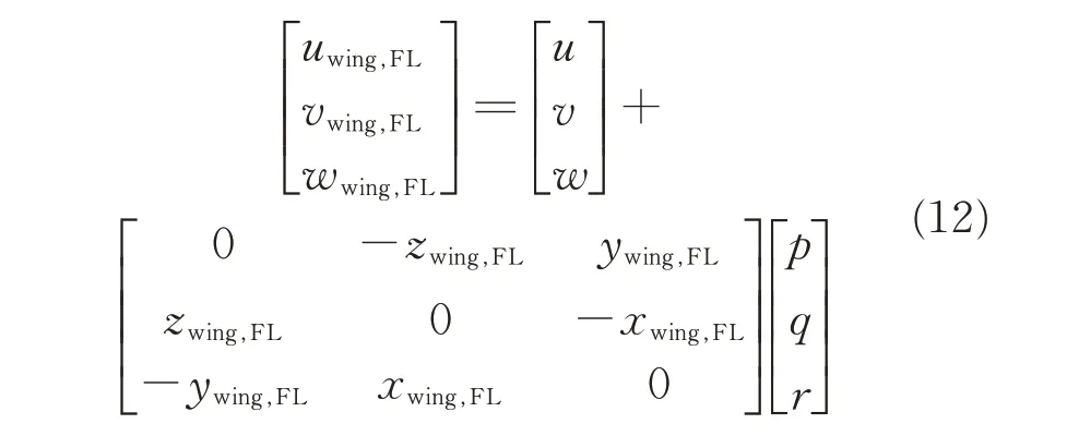
The velocity of the aerodynamic center in the free flow area is the sum of the free flow velocity(u,v,w)and the velocity caused by angular velocity(p,q,r).The velocity of the aerodynamic center in the free flow area is shown in Eq.(12).
Add the velocity in the aerodynamic center of the sliding flow area into Eq.(12),one can obtain
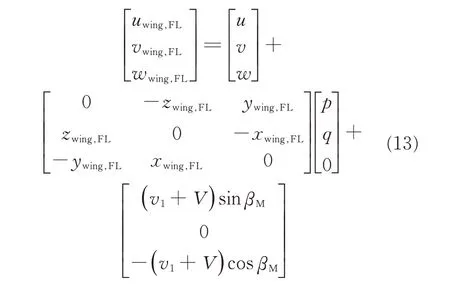
The angle of attack in the free area is shown in Eq.(15).The angle of attack in the sliding flow area is shown in Eq.(16).

where

Thus,the force on the left part of the front wing of the wind axis is shown in Eq.(17).

Convert the force on the left part of the front wing under the wind axis into the force and moment under the body axis,as shown in Eq.(18).

Similarly,the forces and moment on the right part of the front wing are obtained.Compared with the front wing,the rear wing adds lift caused by rudder deflection(δpitchandδroll).The slant angles of the left and right rudder surfaces of the rear wing are defined asδwing,BLandδwing,BR.

1.3 Vertical tail aerodynamic model
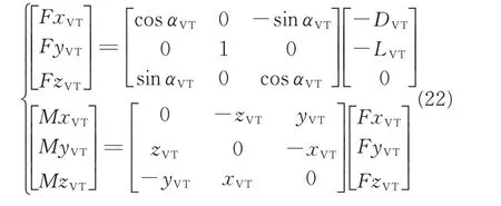
The velocity of the aerodynamic center on the vertical tail is the sum of the free flow velocity(u,v,w)and the velocity caused by the angular velocity(p,q,r),as shown in Eq.(20),where xVT,yVT,zVTare the distance between the pressure center of the vertical tail and the center of gravity of the aircraft.

The force on the vertical tail of the wind axis is shown in Eq.(21),where,SVT,CαL,VT,CD,VT,αVTandα0,VTare the vertical tail area,the slope of the vertical tail lift coefficient,the slope of the vertical tail drag coefficient,the angle of attack of the vertical tail,and the angle of attack of zero lift.

The force and moment in the body axis are shown in Eq.(22).
1.4 Fuselage aerodynamic model
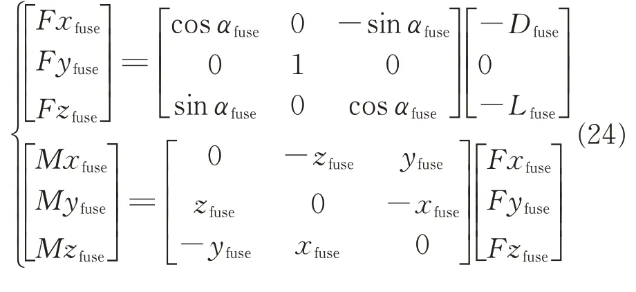
The fuselage aerodynamic center velocity is the sum of the free velocity and the velocity caused by the angular velocity.xfuse,yfuse,zfuseare the distances between the pressure center of the fuselage and the center of gravity of the aircraft.

Fig.4 shows the lift and drag curves of the fuselage at the aerodynamic center at a forward flying speed of 30 m/s.The lift Lfuseand drag Dfuseof other forwarding speeds are obtained by interpolation.
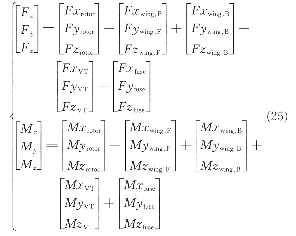
The force and moment in the body axis are shown in Eq.(24).
1.5 Equation of motion
Based on the above analysis,the aerodynamic resultant force and moment of the tilt quad rotor with tilt-wing in the body axis can be obtained.
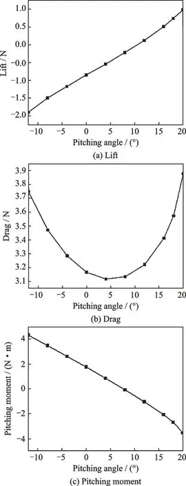
Fig.4 Flying speed being 30 m/s
Eqs.(26,27)are the dynamic and the kinematics equations,where m is the weight of the aircraft,I the moment of inertia;u,v,w the velocity components;ϕ,θ,ψthe Euler angles,and p,q,r the angular velocity components.
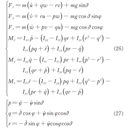
Fig.5 shows the flight dynamic model of the tilt quad rotor.Model input,output and functions of each module are as follows:(1)Input module:Throttle manipulation,pitch manipulation,roll manipulation,yaw manipulation and tilt angle;(2)output module:Velocity(u,v,w),angular velocity(p,q,r),and angle(ϕ,θ,ψ);(3)aerodynamics module:The aerodynamic model,manipulation allocation model,the force and moment model;(4)kinematics module:Six-degree-of-freedom equation and output u,v,w,p,q,r,ϕ,θ,ψ;(5)coordinate conversion module:Conversion of output values from body axis to earth axis.
2 Trimming Result Analysis
Tilt quad rotor with tilt-wing has propeller and wing at the same time.Before trimming,the control decoupling should be performed first.
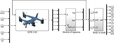
Fig.5 Flight dynamic model
Helicopter mode control decoupling is shown in Fig.6.The length of Fi(i=1,2,3,4)represents the pulling force provided by the propeller,and the direction of Mi(i=1,2,3,4)represents the rotation direction of propeller.When the change of the rotation speed of the two front propellers is opposite to that of the two back ones(the rotation speeds of M1and M3increase,and the rotation speeds of M2and M4decrease),the aircraft will do pitch motion.When the change of the rotation speed of the two left propellers is opposite to that of the two right ones(the rotation speeds of M2and M3increase,and the rotation speeds of M1and M4decrease),the aircraft will do roll motion.When the change of the rotation speed of the propellers on the two diagonals is opposite(such as the rotation speed of M1and M2increase,and the rotation speed of M3and M4decrease),the aircraft will do yaw motion.
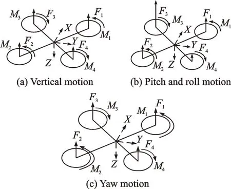
Fig.6 Helicopter mode control decoupling
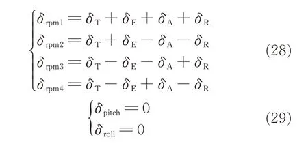
In helicopter mode,the rudder deflection angle is 0°,and the control decoupling methods are shown in Eqs.(28),(29),whereδrpm1,δrpm2,δrpm3,δrpm4are the rotation speed of the four propellers.δTis the throttle revolution,δEis pitch manipulation,δAis roll manipulation,δRis yaw manipulation,δpitch,δrollis rudder deflection angle.
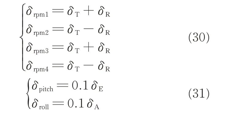
In the fixed wing mode,the rudder surface plays the main control role.The propeller only provides forward tension and yaw direction control coupling.Control decoupling mode is
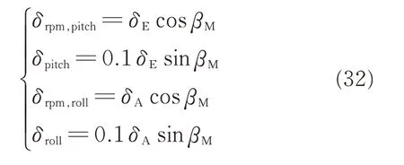
In the transition mode of tilt quad rotor with tiltwing when the tilt angle decreases,the control effect of the propeller becomes weaker,and the control effect of the elevator becomes stronger.Define that tilt angle is 90°for the fixed wing mode and 0°for the helicopter mode.
2.1 Hovering and cr uising conditions
Whether tilt rotor aircraft with tilt-wing or without in the hover state,namely,the tilting angle is 0°,as shown in Fig.7(a),the throttle revolution increases with the increase of forwarding speed.It is mainly caused by the increase of air flow rate of the propeller,thus leading to induced velocity decrease.
The rotation speed of the propeller will increase to generate the same amount of tension.In addition,when the forwarding flight speed increases,the fuselage drag increases.The aircraft lowers its head to balance the fuselage drag,and the pitch revolution manipulation is negative,as shown in Figs.7(b),(d).Since the aircraft is in the pitch down state,the propeller needs to provide part of force to balance the drag and the gravity of the aircraft.In the helicopter mode,the elevator does not participate in the control,and the elevator deflection angle is 0°,as shown in Fig.7(c).
Compared with tilt rotor aircraft without tiltwing,the throttle revolution decreases,as shown in Fig.7(a).The main reason is that when tilt-wing is not taken,the propeller wake will cause certain vertical weight gain,and the propeller rotation speed needs to be increased to balance the vertical force.However,as the forwarding flight speed increases,the drag formed by tilt-wing increases,and the aircraft further lowers its head,as shown in Fig.7(d).When the speed increases,the throttle revolution of the tilt rotor aircraft with tilt-wing rapidly increases.The absolute value of pitch revolution manipulation is larger than that without tiltwing.
When in the cruising state,namely,tilt angles is 90°,the variable of the tilt rotor aircraft with and without tilt-wing are almost same.Similar to the hover state,the throttle revolution increases with the increase of the forward flight speed,as shown in Fig.7(a).When the forwarding flight speed increases,the drag of the whole aircraft increases,and the aircraft lowers its head gradually,as shown in Fig.7(d).Different from the hovering state,the elevator replaces the propeller to take part in the control in the cruising state.
Considering that the forward flight speed of tilt rotor aircraft is small in the helicopter mode,the throttle revolution of the aircraft with tilt-wing is small and the power consumption is small at a low speed.Therefore,from the perspective of the helicopter mode,tilt rotor aircraft with tilt-wing is better than that without tilt-wing.
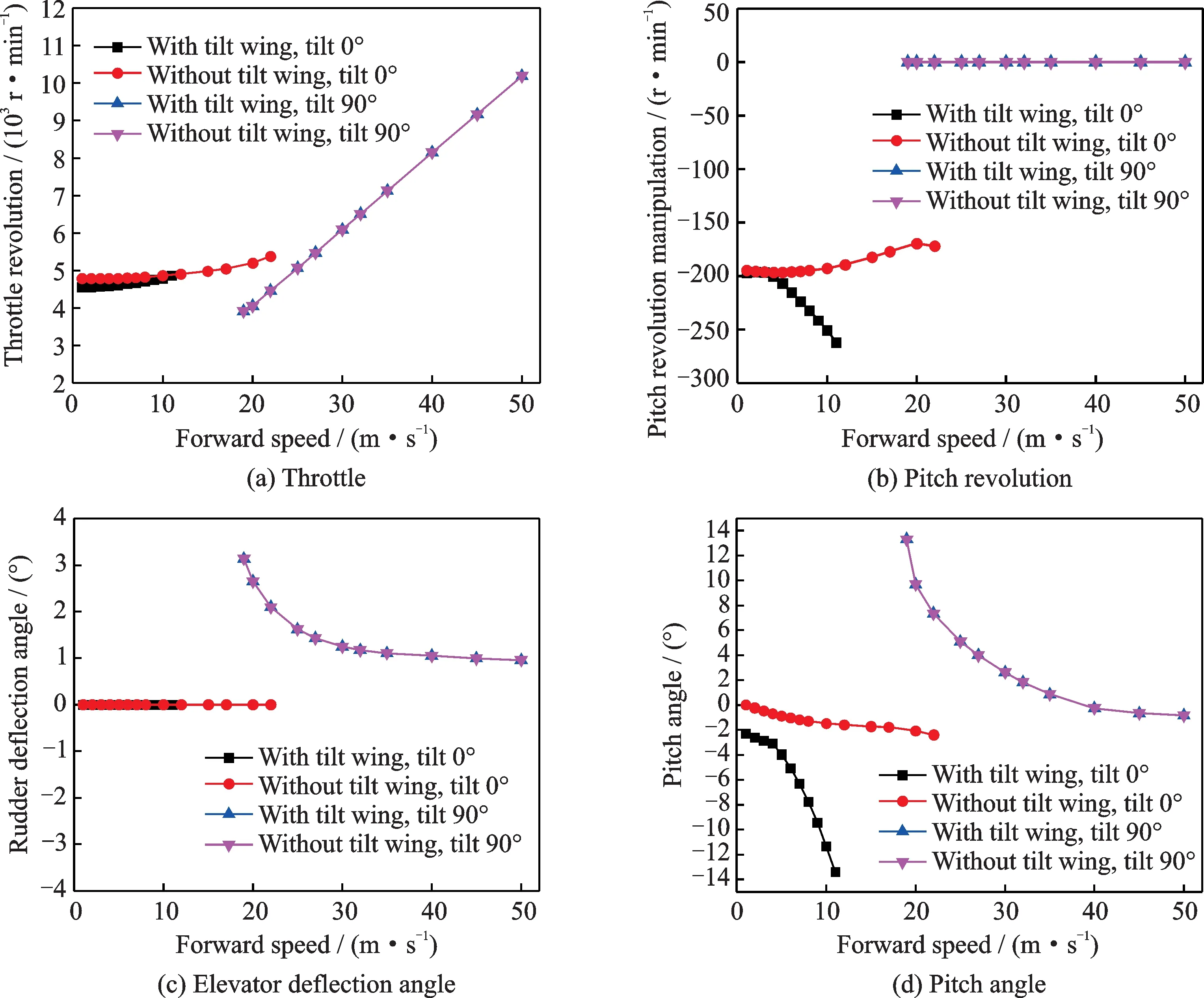
Fig.7 Change of manipulation and attitude angle with velocity
2.2 Cases of Tilts 30°and 60°
Similar to the helicopter mode,at nacelle tilting 30°,for both tilt rotor aircraft with and without tilt-wing,throttle revolution increases with the increase of forwarding speed,as shown in Fig.8(a).But the value of throttle revolution is smaller than that of the helicopter mode.This is at nacelle tilting 30°,the wing provides a certain amount of lift,and the lift caused by propeller thus decreases.With the increase of forward flight speed,the aircraft further lowers its head,as shown in Figs.8(b),(d).The elevator starts to participate in the control,as shown in Fig.8(c).
Compared with the tilt rotor aircraft without tiltwing,the pitch manipulation and elevator deflection angle of the tilt rotor with tilt-wing further increase negatively.The aircraft further lowers its head.It is because when the nacelle turns to 30°,the aircraft has a certain speed,and the drag of the aircraft is larger than that without tilt-wing.In addition,the propeller wake does not vertically hit on the wings,and the drag value of the tilt rotor with tilt-wing is still large.The throttle revolution required by the tilt rotor with tilt-wing is larger,as shown in Fig.8(a).
When tilting at 60°,throttle revolution,pitch revolution manipulation,the elevator deflection angle and pitch angle changing with the forward speed are similar to tilting at 30°.Compared with tilting at 30°,when nacelle tilting at 60°,the throttle revolution of the tilt rotor with tilt-wing decreases,and it is mainly because the tilt-wing produces smaller drag when the nacelle tilting at 60°.The throttle revolution of the tilt rotor without tilt-wing increases,and it is mainly due to the fact that the propeller under vertical inflow is larger at the same forwarding speed when the nacelle tilting at 60°,as shown in Fig.8(a).
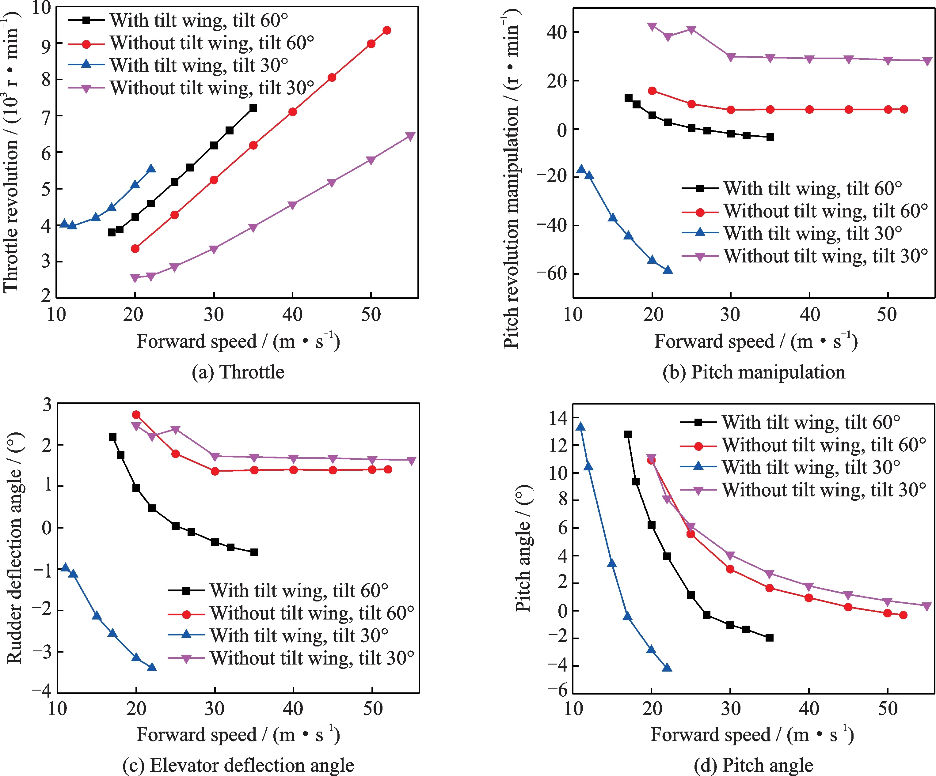
Fig.8 Change of manipulation and attitude angle with velocity
3 Transition Corridor
On the basic of the trimming calculation in the previous section,the maximum and minimum velocities at each tilt angle are calculated,and then the transition corridor of tilt quad rotor with tilt-wing and the tilt quad rotor without tilt-wing are obtained.The calculation process is shown in Fig.9.The boundary of small velocity is mainly determined whether the wing reaches the stall angle of attack,and the maximum velocity boundary is mainly determined whether the propeller power reaches the maximum power.
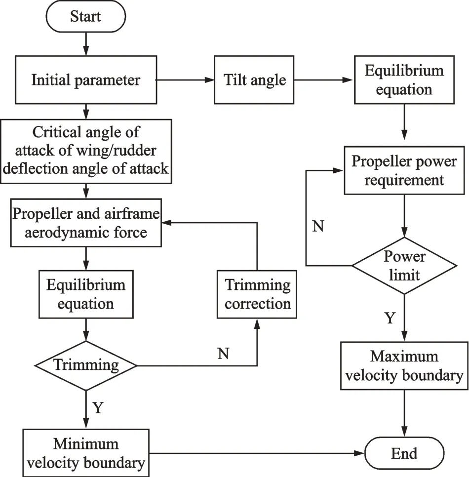
Fig.9 Calculation process of transition corridor
Fig.10 shows the calculated transition corridor,where tilt angle is 90°for the helicopter mode and 0°for the fixed wing model,the black line is the boundary of minimum speed of the tilt quad rotor without tilt-wing,the red line is the boundary of the maximum speed of tilt quad rotor without tilt-wing,the blue line is the boundary of the minimum speed of tilt quad rotor with tilt-wing,and the purple line is the boundary of the maximum speed of tilt quad rotor with tilt-wing.
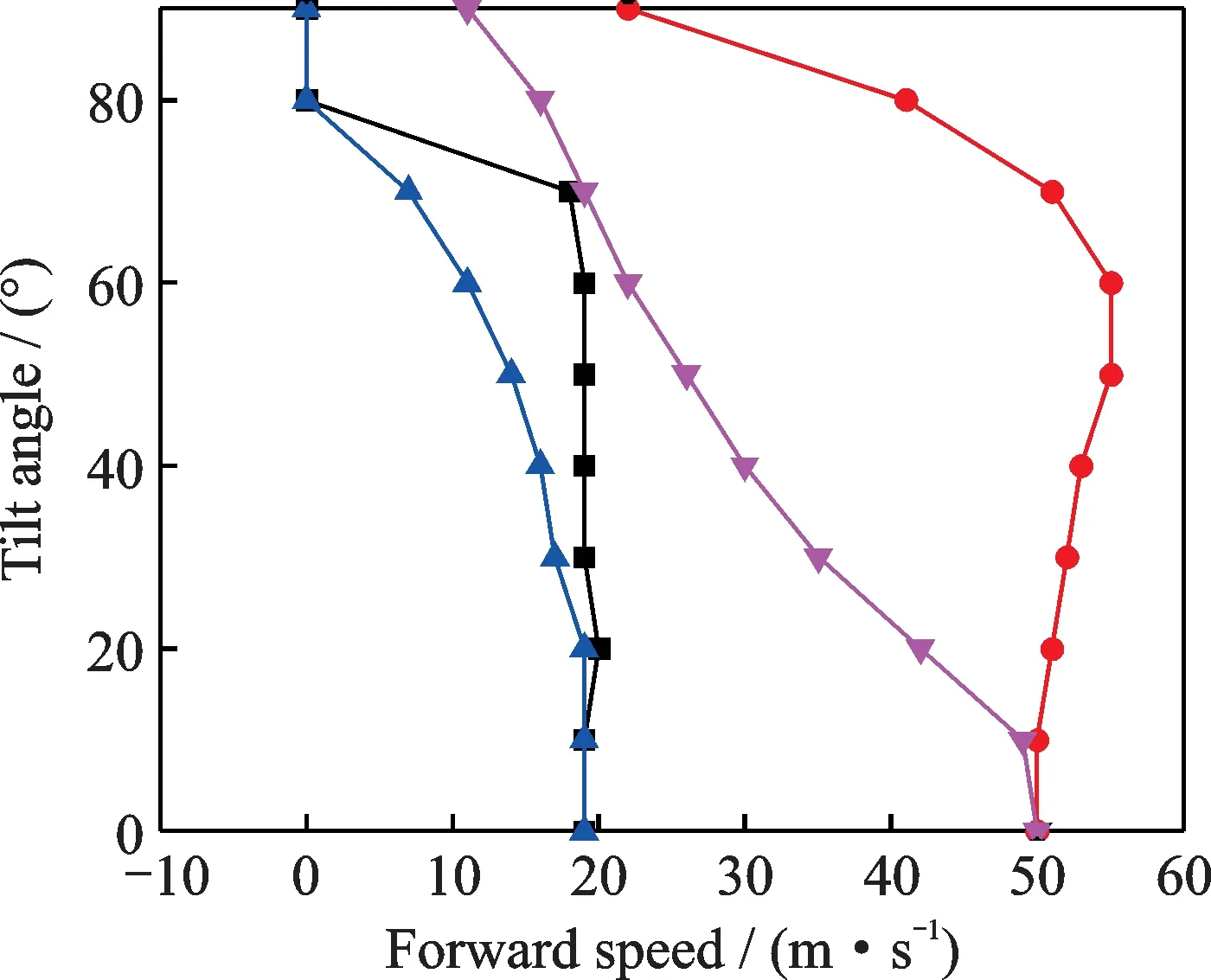
Fig.10 Tilting transition corridor
It can be seen that the transition corridor of tilt quad rotor with tilt-wing is narrower than that without tilt-wing.It is due to the fact that the wing with the tilt-wing will produce greater drag when in the helicopter mode and when the tilt angle is small.To balance the drag,the rotation speed of the propeller should be increased to provide forward force.
4 Stability Analysis
On the basic of the trimming state,the linearized model of the tilt quad rotor is obtained by using the small disturbance hypothesis,as shown in Eq.(33),where A is the system stability matrix and B the control derivative matrix.Furthermore,the stability of the aircraft is discussed by obtaining the characteristic roots in each state.

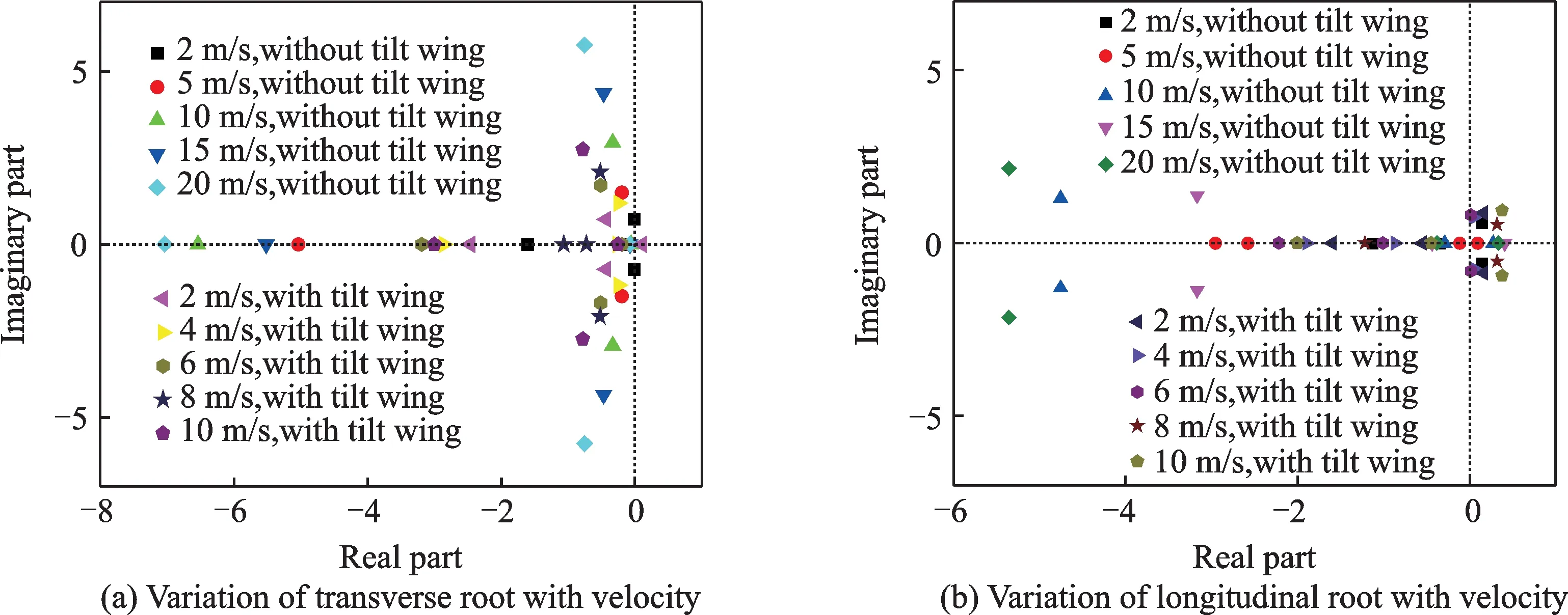
Fig.11 Hovering state
In the hovering mode without tilt-wing,as shown in Fig.11(a),with the increase of velocity,the natural frequency of Dutch rolling mode increases and the damping remains unchanged.As shown in Fig.11(b),with the increase of velocity,the aerodynamic force of the wing increases and the angle of attack instability is improved.The short period gradually turns into a pair of conjugate negative roots,and the longitudinal long period mode turns into a pair of negative real roots,which is similar to the hovering oscillation mode of a helicopter.The root value of transverse roll and spiral mode increases negatively at first and then decreases,which is mainly related to the downwash of propeller to wing.
In the cruising mode,as shown in Fig.12(a),with the increase of speed,roll damping and yaw damping,roll mode and spiral mode time constants,and the root value increase negatively.When the speed increases,the natural frequency increases and the damping is approximately constant,which is similar to the variation of the root trajectory of conventional fixed-wing aircraft.
As shown in Fig.12(b),in the longitudinal plane,with the increase of velocity,the natural frequency and damping ratio of the short-period mode increase,the damping of the long-period mode increases,and the natural frequency decreases at first and then increases,which is different from the conventional fixed-wing aircraft.When the speed increases,the inflow of the propellers increases,the tension decreases,the rise torque is generated.When the aircraft raises its head,the propeller inflow decreases,and the tension increases,the bow torque is generated,and it has the static stability of angle of attack.
Under the tilt angle of 30°and 60°transverse plane,as shown in Fig.13(a)and Fig.14(a),it is similar to the distribution of characteristic roots in the cruising state.In the longitudinal plane,as shown in Fig.13(b)and Fig.14(b),it is similar to the hovering power distribution.It is mainly because the influence of the propeller in the longitudinal plane is greater than that in the transverse plane.
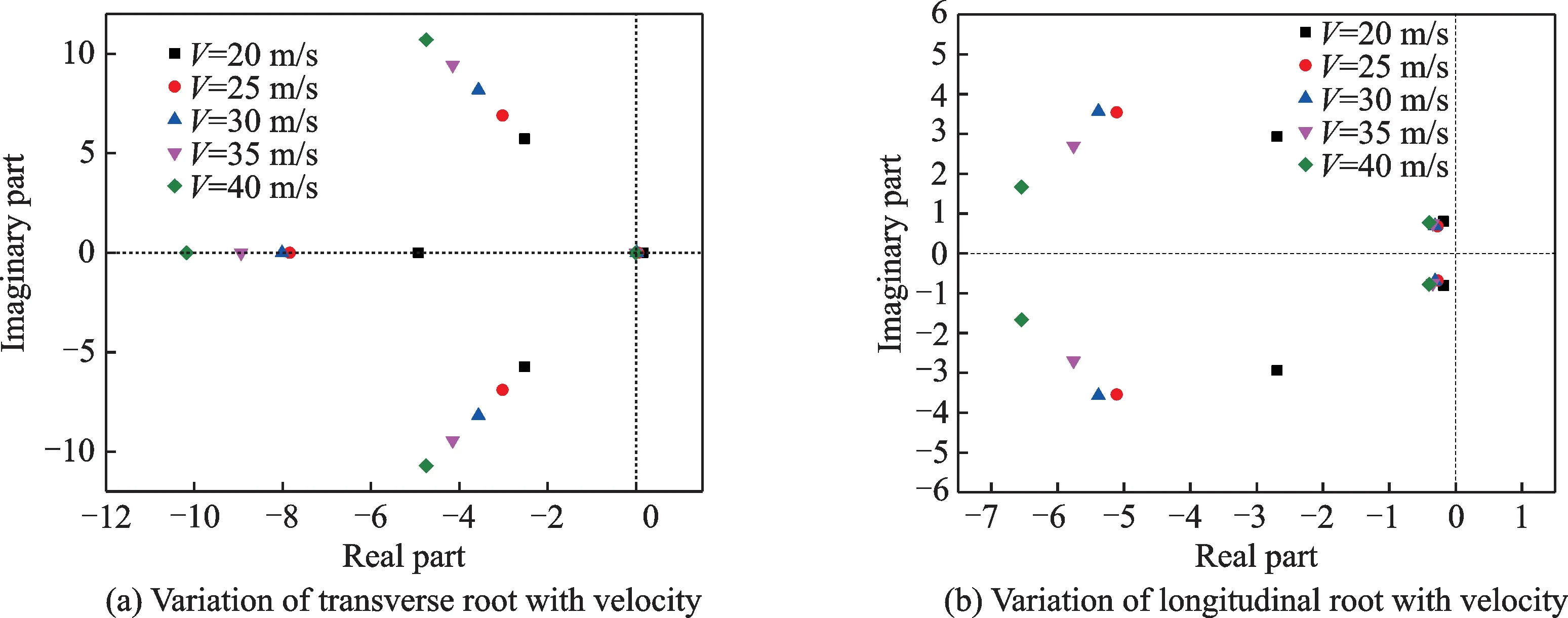
Fig.12 Cruising state
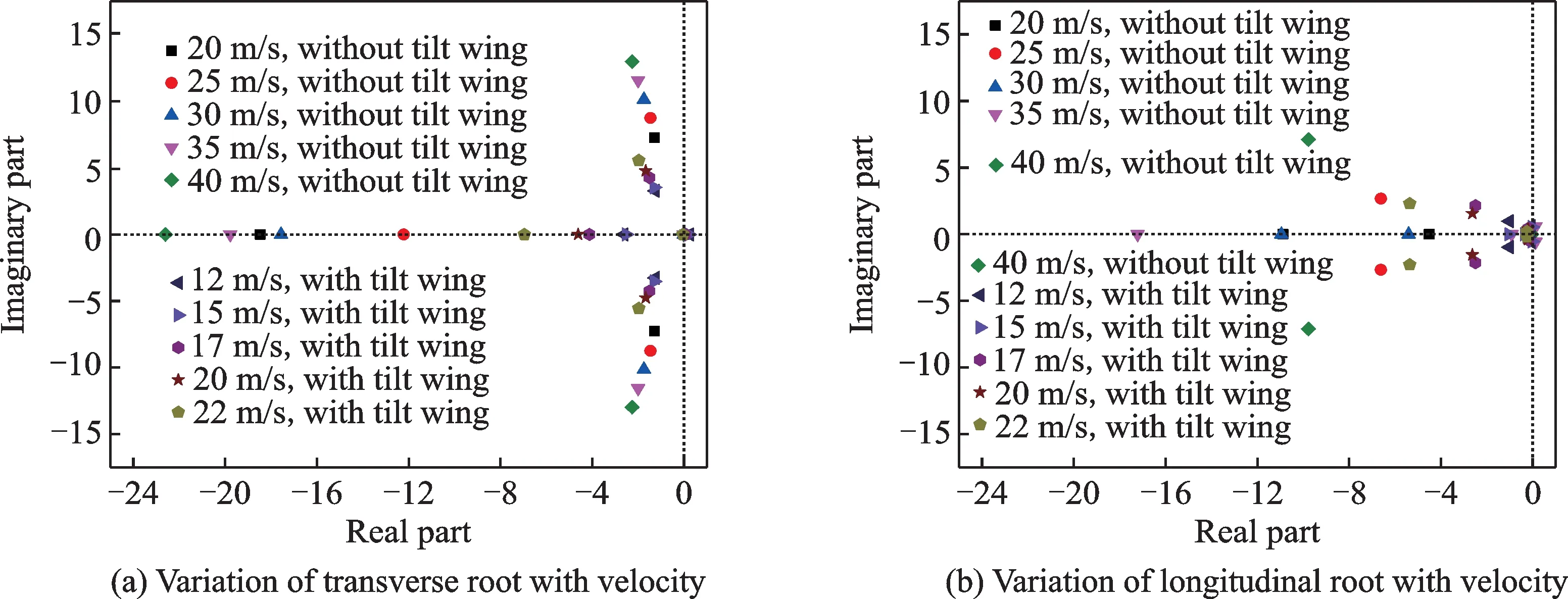
Fig.13 Tilt angle 30°
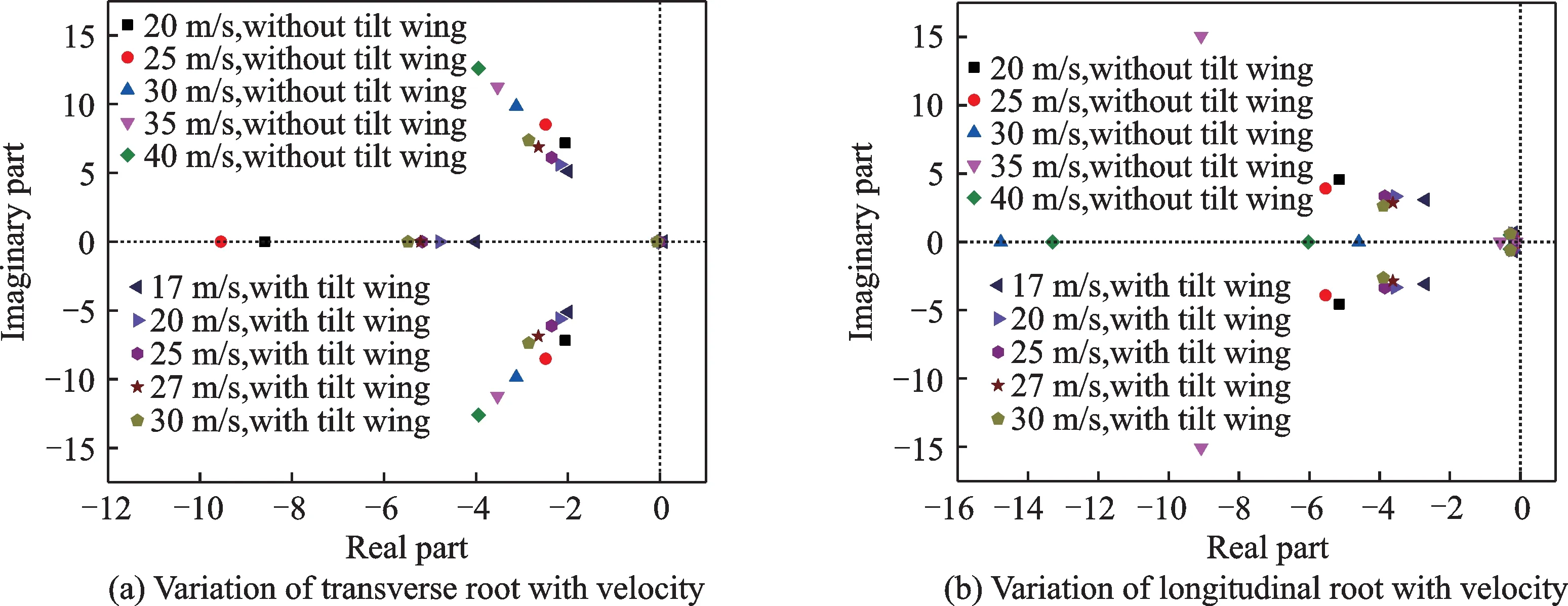
Fig.14 Tilt angle 60°
Compared with the tilt quad rotor without tiltwing,the Dutch roll damping ratio of the rotor increases and the natural frequency approximately remains unchanged.At the other modes,damping decreases and its change is not determined.It is because the tilt-wing is always in the state of large angle of attack and the aerodynamic force changes greatly.But except for the tilting at 30°,the characteristic root is in the left half plane,which still has a good stability.
5 Manipulation Response
Using time domain analysis method and tilt quad rotor mathematical model to study the manipulation response of the tilt quad rotor with tilt-wing.For the throttle and longitudinal/lateral control of the vehicle with tilt-wing at the tilt angle of 0°,30°,60°and 90°,step control input is given,respectively,and the response curves obtained are shown in Figs.15—17.
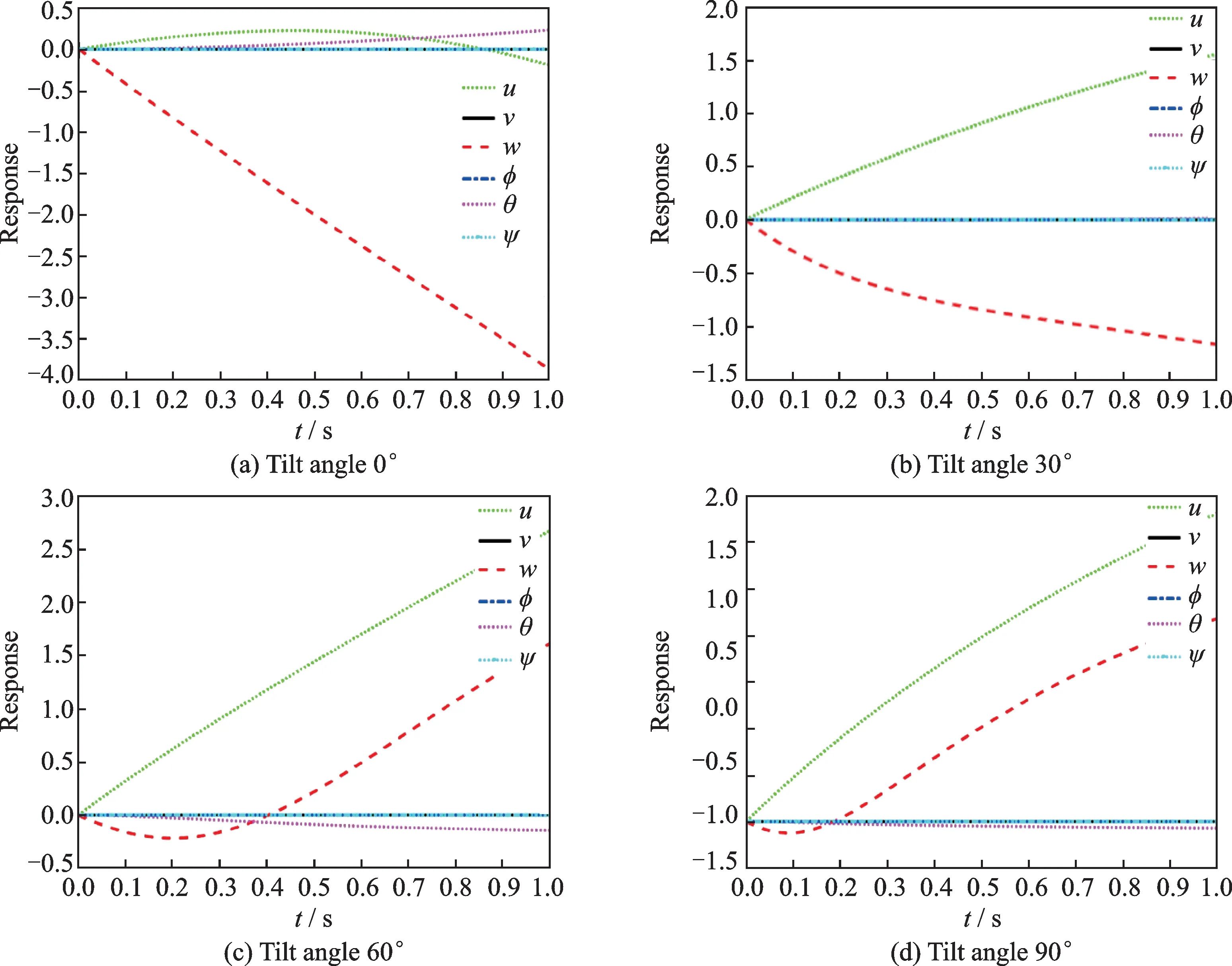
Fig.15 Manipulation responses of throttle
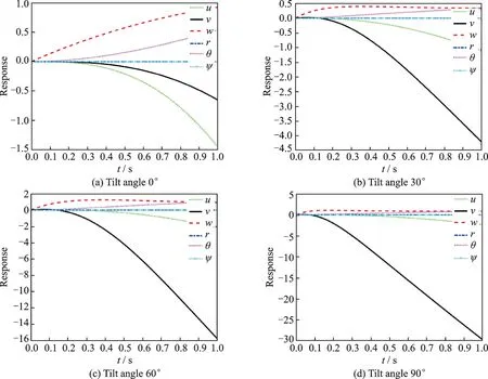
Fig.16 Manipulation response of longitudinal
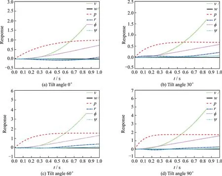
Fig.17 Manipulation response of transverse
In Fig.15,the step control of the throttle triggers a change in the vertical velocity.The positive throttle control input makes the vertical motion velocity of the aircraft increase,and the response of the vertical motion velocity to the throttle input is stable.It finally tends to be stable.There is a firstorder inertial relationship between the vertical velocity and the throttle(Fig.15(a)).When the tilt angle is 30°(Fig.15(b)),the step control of the throttle triggers a change in both vertical and forward velocities.The positive throttle control input affects both vertical and forward velocities of the aircraft,and the relationship between the forward velocity and the throttle is also the first-order.Compared Figs.15(a),(b),(c)and(d),with the increases of tilt angle,the forward velocity increase and the vertical velocity decreases.It is because with the increase of the tilt angle,the forward force increases and the vertical force decreases.
In Fig.16,the step control of the longitudinal gives rise to pitch angle velocity,pitch attitude angle,forward velocity,and vertical velocity.The positive unit longitudinal input causes the positive pitch angle velocity of the vehicle.The pitch angle increases,the vehicle raises its head,and then causes a negative forward flight velocity and a positive vertical velocity(The signs are different because of the definition of the coordinate system).At the hovering state,the response of pitch attitude diverges rapidly.With the increase of tilt angle,the response of pitch attitude converges gradually.It is same to stability analysis.Similarly,pitch attitude angle and pitch angle velocity present integral relationship.Meanwhile,with the increase of tilt angle,forward velocity,pitch attitude angle and pitch angle velocity decrease and the vertical velocity increases.
Fig.17 shows the transverse response,the transverse manipulation input makes the vehicle transverse velocity,roll angle velocity and roll angle change,and causes the course angle velocity and course angle change.In the hovering and cruising modes,the course angle velocity and course angle caused by transverse manipulation input changes.However,in the transition mode,it changes greatly.In the transition mode,the lateral-directional coupling is strong.
6 Conclusions
The aerodynamic models of tilt quad rotor aircraft with tilt-wing,propeller,wing,fuselage and vertical tail are established,and then the flight dynamic model of the aircraft is established.On this basis,the trimming and stability of the tilt quad rotor with and without tilt-wing are compared and analyzed.It can be seen from the trimming results in the hovering state that,because of the existence of tilt-wing,the downwash of the wing caused by propeller wake is reduced,the vertical weight of the aircraft is reduced,and the propeller tension required is small,and the power consumption in the hovering state is small.Considering that the state of tilt quad rotor is mainly hovering and cruising,and the power consumption in the hovering state is much higher than that in the cruising state.The tilt-wing has certain significance for tilt quad rotor aircraft,which is conductive to reducing its energy consumption,thus increasing its endurance time and improving its endurance performance.Compared with tilt quad rotor aircraft without tilt-wing,the Dutch roll damping ratio of the tilt quad rotor with tilt-wing is larger and the other modes have certain stability.It can be seen from the manipulation response analysis that the lateral-directional coupling is strong in the transition mode.
杂志排行
Transactions of Nanjing University of Aeronautics and Astronautics的其它文章
- BeiDou B1I/B3I Signals Joint Tracking Algorithm Based on Kalman Filter
- Impact Analysis of Solar Irradiance Change on Precision Orbit Determination of Navigation Satellites
- Characterization of Self-driven Cascode-Configuration Synchronous Rectifiers
- Cooperative Search of UAV Swarm Based on Ant Colony Optimization with Artificial Potential Field
- H∞Preview Control for Automatic Carrier Landing
- Single-Phase to Three-Phase Inverter with Small DC-Link Capacitor for Motor Drive System
