Manufacturable pattern collage along a boundary
2019-02-17MinghaiChenFanXuandLinLu
Minghai Chen,Fan Xu,and Lin Lu()
Abstract Recent years have shown rapid development of digital fabrication techniques,making manufacturing individual models reachable for ordinary users.Thus,tools for designing customized objects in a user-friendly way are in high demand. In this paper,we tackle the problem of generating a collage of patterns along a given boundary,aimed at digital fabrication.We represent the packing space by a pipe-like closed shape along the boundary and use ellipses as packing elements for computing an initial layout of the patterns.Then we search for the best matching pattern for each ellipse and construct the initial pattern collage in an automatic manner.To facilitate editing the collage,we provide interactive operations which allow the user to adjust the layout at the coarse level.The patterns are fi ne-tuned based on a spring-mass system after each interaction step.After this interactive process,the collage result is further optimized to enforce connectivity.Finally,we perform structural analysis on the collage and enhance its stability,so that the result can be fabricated.To demonstrate the effectiveness of our method,we show results fabricated by 3D printing and laser cutting.
Keywords pattern collage;interactive design;digital fabrication
1 Introduction
Given thedevelopmentsin digitalfabrication,especially in 3D printing and laser cutting techniques,inexperienced users now have the possibility to manufacture personal products at an affordable cost.This stimulates a high demand for user-friendly design tools for various applications,to help users to create custom objects in an easy manner. Fabrication requirements must be considered by such tools to ensure that the digital models can be manufactured without further adjustment.Several such tools have been proposed,attempting to facilitate the fabrication aware design process in different ways[1-4].
Patterns play an important role in 2D graphic design,and are frequently used in applications for ornaments,covers,decoration,etc.Designers and artists often make use of multiple intricate and exquisite patterns to represent a large,meaningful shape.Such an art form is called a collage,or a montage,and such an artistic composition is created by pasting elements like photos and clippings onto a canvas.Photo collages have been well studied[5,6]and now can be automatically generated in most cases,as seen in Fig.1(a).However,pattern collages have received less attention.Remarkable work by Kwan et al.[7]proposed an automatic method for constructing a collage of patterns to fi ll a given region(see Fig.1(b)),using a scale-and rotation-invariant 2D shape descriptor,namely thepyramid of arc-lengthdescriptor(PAD).In our work,we focus on generating a collage of patterns along a given boundary,in the context of digital fabrication(see Fig.1(c)).
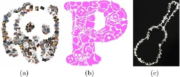
Fig.1 (a)A photo collage automatically generated ongetloupe.com.(b)A shape collage produced by Ref.[7].(c)A 3D printed boundaryconstrained collage produced by our method.
The proposed pattern collage problem is non-trivial,as the difficulty is equivalent to solving the problem of packing irregular shapes in a given boundary,which is a combinatorial NP-hard problem.More importantly,it is hard to evaluate the aesthetics of the collage result.Thus,we propose to provide interactive operations for users,to facilitate adjustment of the placement of the patterns.Initial packing results are automatically generated fi rst.Users have the freedom to adjust the placement of the pattern units,in a simple and approximate manner.After each interaction process,the patterns are locally optimized through a spring-mass system.Finally,the collage result is optimized to satisfy the fabrication constraints including full connectivity and stability.Our work makes the following contributions:
·We propose the problem of generating a collage of patterns along a given boundary in the context of digital fabrication.
·We simplify the collage design process into heuristic ellipse packing,coarse-level user interaction,and fi ne-level optimization of the element placement.
·We integrate the design and optimization steps in a system that produces structurally sound,manufacturable models ready for 3D printing or laser cutting.
2 Related work
2.1 Pattern collage
Pattern collage is a traditional form of artistic design.There are several related computational methods for generating pattern collages.Kim and Pellacini[8]introduced a method for packing image tiles into an image container by matching the color of the image tiles to colors in the image container.Hu et al.[9]extended the tile arrangement on curved surfaces and solved the problem by hybrid optimization,i.e.,continuous con fi guration optimization and discrete combinatorial optimization.They further applied optimization to packing irregular objects in 3D space[10].Kwan et al.[7]proposed a bottom-up solution to generate collages with arbitrary and irregular shapes in a scale-invariant domain,using a scaleinvariant shape descriptor called PAD.They further adopted this descriptor to identify a queried shape in a cluttered image[11].Saputra et al.[12]presented a technique for drawing ornamental designs consisting of simple elements that are carefully arranged and deformed to conform to a user-speci fi ed fl ow.As a particular kind of patterns,several related methods focus on generating calligraphic packing of letters.Xu et al.[13]developed a solution to the calligraphic packing problem based on dividing up a target region into pieces and warping a letter into each piece.Zou et al.[14]generated legible compact calligrams automatically and kept the alphabetical order,unlike Ref.[13].Unlike the above two methods,Zhang et al.[15]de fi ned a semanticshape similarity metric for an image and a typeface and created ornamental typefaces using internet images.Researchers have also tackled 3D collage[16,17],solving the problem in a bottom-up approach.
2.2 Geometric texture synthesis
Texture synthesis methods for creating decorative patterns on surfaces have been studied well in the computer graphics community.We only brie fl y review such work in the context of digital fabrication.Zhou et al.[18]generated single connected ornaments along curves by considering 1D pattern synthesis while constraining the topology.Dumas et al.[19]synthesized manufacturable patterns along surfaces by combining topology optimization with appearance optimization. Mart´ınez et al.[20]targeted the synthesis of fl at shapes manufactured by laser cutting and considered optimization of the appearance under structural constraints. Chen et al.[21]synthesized fi ligree-like structures along surfaces.They relaxed the packing problem by allowing appearance-preserving overlaps between elements.Their method produces appealing patterns,but cannot guarantee that the base shape is preserved.They further proposed a method for generating packed patterns on a base surface with a set of fl at tiles[22].Zehnder et al.[23]explored the interactive design of curve networks on surfaces,and simulated the curves as elastic rods,such that a tight packing is achieved by minimizing deformation.The produced airy curve networks can be fabricated on high-end printers.
2.3 Interactive layout design
User interaction has always been regarded as an important aspect of pattern layout design.Reinert et al.[24]presented a framework to perturb 2D objects in a canvas by equalizing the gaps between objects.The method can infer the desired layout of all primitives from the interactive placement of a small subset of example primitives.Xu et al.[25]proposed a method to automatically derive desired groups present in the selected elements and carry out arrangement according to a user command.Wang et al.[26]presented a method for consistently editing word clouds that allows users to edit words while preserving the neighborhoods of other words.
Our objectives include that users only need to perform coarse operations on the arrangement of the pattern units;after each operation,the patterns are locally relaxed into a tight distribution,maintaining neighborhood relationships.
3 Overview
Our pattern collage algorithm takes a number of patterns and a closed curve boundary as the input.The output is a visually pleasing pattern collage along the given boundary composed of connected and partially overlapping patterns,which is manufacturable and has structural stability.
The collage result has three constraints as follows.Firstly,all patterns must lie within the pipe-like shape established along the given pro fi le.Secondly,there must be at least one intersection point between each pair of neighboring units in order to ensure connectivity.Thirdly,the result should be manufacturable and structurally sound.
Users have the freedom to control the placement of each pattern unit.After user interaction,the pattern layout is optimized while maintaining the neighborhood relationships between the patterns.The fi nal result is fully connected,manufacturable,and stable.
The pipeline of our proposed algorithm is shown in Fig.2. Firstly,we create the packing space by generating an inner boundary from the outer boundary using an image erosion operation.The pipe-like shape is regarded as the packing domain(see Fig.2(a)).Secondly,we transform the initial irregular shape packing problem into an ellipse packing problem,taking ellipses as proxies for the pattern units.We use a heuristic algorithm to pack the given number of ellipses in the domain(see Fig.2(b)).Afterwards,we match each ellipse with a pattern from the library and transform the selected patterns to match the placements of their proxies(see Fig.2(c)).
We provide the users with simple interactive controls for rotation,translation,and scaling of selected patterns.After each interaction step,we relax the pattern layout and obtain an optimized distribution using a spring-mass system.Finally,we enforce full connectivity of the patterns and perform structural analysis on the extruded volume.Any weak parts are strengthened so that the model is manufacturable and stable(see Figs.2(d)and 2(e)).
4 Technical details
4.1 Pre-processing
We fi rst simplify the input boundary.Since the points forming the input are usually more dense than necessary,we reduce the number vertices of the initial contour by thediscrete contour evolution(DCE)method[27],without changing the shape detail.For example,the dove collage in Fig.2 initially consisted of 2844 points;we simpli fi ed it to 100 points.The simpli fi cation process iteratively deletes whichever point contributes least,where the contribution of a point depends on the angle between the two segments connected to it and the lengths of these two segments.The cost function for a point’s contribution is

Fig.2 Given a curve boundary,we generate an inner boundary to build the packing space(a)and compute an ellipse packing in the pipe-like shape guided by the medial axis(b).Then we fi t each ellipse with the best matching pattern unit to form the initial collage(c).The user can interactively tune the placements,which is followed by local optimization of the distribution and connectivity enforcement(d).The fi nal result can be 3D printed after simple extrusion(e).

wheres1ands2are the two line segments joining the current point to its two neighbors,β(s1,s2)is the angle between the two line segments,andl(s1)andl(s2)refer to the length of the two line segments.
Next,we generate an inner boundary by eroding the original boundary.Together with the origin boundary,these constitute a pipe-like space in which we collage the pattern units.The advantage of erosion over offsetting is that the erosion result cannot be self-intersecting.The degree of erosionkis chosen according to the resolution of the image:users can changekin the range[0.05,0.2].The lower bound depends on the precision of the desktop 3D printer while the upper bound of 0.2 is empirically determined.The pipe width is determined by the degree of erosion.An excessive pipe width leads to a meaningless inner boundary,but if the pipe width is too small,the patterns are small and indistinguishable.
Next,we generate the medial axis within the pipelike shape.
4.2 Initial layout generation
4.2.1Ellipse packing
This step generates an initial layout along the pipe-like shape.To avoid frequent calculations of intersections between non-convex patterns,we use an ellipse as the proxy for each pattern in this initial stage.This turns our problem to an ellipse packing problem.Optimal ellipse packing problems belong to the NP-hard class,and thus heuristic algorithms are typically employed to solve them[28,29].
We also use a heuristic approach and generate an initial ellipse packing from uniformly sampled seeds.Given the user-speci fi ed number of patterns,we equidistantly sample seed points on the medial axis of the pipe,and generate circles at them tangent to both inner and outer boundaries(see Fig.3(a)).Then we deform the shape of each ellipse along the medial axis iteratively,with the constraints that no overlap occurs between ellipses and all ellipses stay inside in the region bounded by the inner and outer boundaries(see Fig.3(b)).
4.2.2Ellipse-to-pattern matching
We need to fi nd the best match between proxy ellipses and pattern units as shown in Fig.4.We compute the aspect ratio,denotedλ,of each ellipse.Each pattern unit in the library has an associated oriented bounding box(OBB);we fi nd the pattern unit whose OBB aspect ratio is closest toλ.Then we transform the selected pattern by translation,rotation,and scaling to place it to conform to the ellipse.
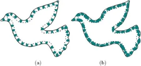
Fig.3 Initial ellipse packing.We uniformly sample circles inside the pipe(a),and deform each into an ellipse until it touches its neighbour or the pipe boundary at more than two points(b).
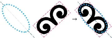
Fig.4 For each ellipse(left),we fi nd the best matching pattern(middle)and replace the ellipse by affinely transforming the pattern(right).
4.3 User interaction
4.3.1Overview
We provide an interface for users to easily edit the pattern collage.Users only need to edit the patterns at a coarse level,using rotation,translation,and scaling.After each editing operation,the layout is automatically optimized within the pipe boundary.We follow the method proposed by Jaramillo et al.[30]and use a spring-particle system to locally adjust the collage.The spring model has two classes of forces,those between each unit and its neighbors,and those between each unit and the boundary of the pipe-like shape.Figure 5 shows two examples of pattern adjustment based on the spring model after interaction.
We use simple rules to detect whether two pattern units are neighbors.If the line segment between the centers of the two units has no intersections with the other patterns,or the inner and outer boundaries,then the two units are regarded as neighbors.
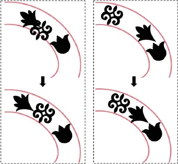
Fig.5 User edited patterns(top)are afterwards optimized to a force balancing position(bottom).
4.3.2Spring-mass system
To build the spring-mass system,for each pattern,we add springs connecting it to its neighbors and the inner and outer shape boundaries.The endpoints of each spring are thus either on the center of a pattern or on a boundary. We regard each endpoint as a particle and group the particles into two types,free particle representing a pattern,and fi xed particles on the boundaries.Only the positions of the free particles are optimized by the spring-mass system,driving an update to the pattern collage accordingly.
LetNbe the number of particles.We assume that the particles have the uniform massM.For each particlei,0≤i<N,let its position bepi,and its velocity beωi.We represent each spring by parameters(pi,pj,l0,ks,kd),wherepiandpjare the two particles at its ends,l0is its length in the rest state,ksis its elastic modulus,andkdis its damping coefficient.The rest state spring lengthl0between two free particles is computed as the distance between the two proxy ellipses along the medial axis.For springs between free particle and fi xing particle,l0is the distance from the initial proxy ellipse to the appropriate boundary.
By Hooke’s law,the force exerted on the spring betweenpiandpjis

while the damping is

The total force on a free particlepiis

whereN(pi)denotesalltheparticlesin the neighborhood ofpi,including the fi xed particles on the boundaries.
The velocity and position of each free particlepiare determined by the values in the last time state:

After each user interaction,we compute the forces on all the springs and update positions of the free particles,until an equilibrium state is reached for each free particlepi,i.e.,Fi=0.Having updated the positions of the free particles,the patterns are updated accordingly,and all fi xed particles are recomputed.
4.4 Structural optimization
4.4.1Connectivity enforcement
To satisfy the fabrication constraints, global connectivity is required for the collage result.However,the connectivity is not ensured by the distribution adjustment governed by the spring-mass system.To achieve connectivity,we enforce each pattern unit to intersect each of its neighbors.As shown in Fig.6,we simply scale up each pattern to meet its neighbors if any gap exists.We note that the pattern might pass beyond the pipe-like region during local magni fi cation,but we consider this to be acceptable in our algorithm.
4.4.2Stability enhancement

Fig.6 (a)Before connectivity enforcement.(b)After connectivity enforcement by local scaling.
We extrude the pattern collage result to obtain a 3D model and perform structural analysis using FEM.We use the OOFEM library[31]to compute the stress if eld of the shell model(using a thickness of 2 mm)and identify any weak parts where the stress is larger than the yield value for the given material.Our experiments used a yield value of 10 MPa for PLA material.
To simulate actual external force conditions,we perform structural analysis and optimization in two phases.We fi x the leftmost and rightmost boundaries as boundary conditions.In the fi rst phase,we apply pulling forces from vertically above and below to the model(Fig.7(a)).The forces are applied to each face of the middle of both sides.The pulling force on each face was 100 N for the Dove model.We detect weak regions and iteratively reinforce such regions by local dilation until the collage model is strong enough(see Fig.7(b)).For each dilation,we use a 3×3 fl at structuring element.FEM analysis is re-performed after each local dilation step.
In the second phase,we apply uniform inward compression forces to each face of the model in a normal direction,and optimize the model in the same way(see Figs.7(c)and 7(d)).The compression force on each face is 15 N here.Our experiments show that typically 3-5 iterations are needed,depending on the external forces.
Stability enhancement is only performed for 3D printed models;for laser cutting applications,only connectivity enforcement is needed.
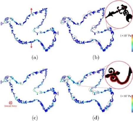
Fig.7 Structural analysis(a,c)and optimization(b,d)of the shape.Weak parts are strengthened by dilation(circled in red)in(b,d).The shape is colored by stress.
5 Results
We have implemented our method in C++,using a Windows 10 system with a 3.6 GHz Intel Core i7-7700K CPU and 16 GB RAM.In the pre-processing step,the initial contour boundary of around 2-4 thousand points is uniformly simpli fi ed to 100 points.
The computational time of the initial layout generation is around 2 seconds.After the location or orientation of a pattern is changed,the spring system works in real time.The time for structural optimization is about 2 minutes on average for the examples shown.
We constructed a pattern library containing different categories of patterns including ornamental elements and animals.Figure 8 shows some of these ornamental patterns.
We considered the effects of varying the parameters of pipe width,k,and number of patterns,m.Figure 9 shows the results in the pipe with different widths.Figure 10 shows the results with different numbers of pattern units.
We invited 30 volunteers to evaluate our pattern collage system.Each user was required to design a single pattern collage using our system.We recorded the editing process and collected feedback from the users.We found that most volunteers fi nished their design after 6-8 interactions.In particular,two volunteers gave feedback that they enjoyed the interaction process rather than simply getting a design result directly.
We also generated spiral lines instead of the medial axis in the shape to guide distributions of the patterns,as shown in Fig.11.

Fig.8 Part of the library of ornamental patterns.

Fig.9 Left to right:collage results using pipe widths of 0.18,0.08,and 0.05(number of patterns m=45).
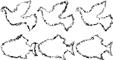
Fig.10 Left to right:collage results with 25,35,and 45 patterns(pipe width k=0.08).
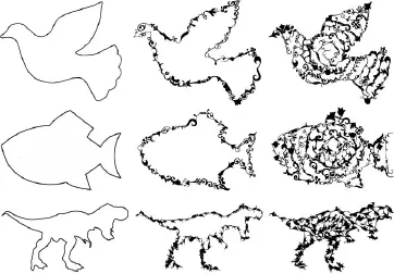
Fig.11 Pattern collage results following spiral lines.
To examine the aesthetics of our results,we invited 30 volunteers for the user study.Firstly,each user was asked to choose the more aesthetically pleasing result amongst the initial shape and the pattern collage results along the shape boundary.User study results are listed in Table 1,which shows the number of users that picked each pattern as their favorite.Secondly,users were asked to pick their favorite from the collageresults along the spiral lines and along the shape boundary;user study results are in Table 2.The results show that although the pattern collages are found acceptable by most users,they have varying preferences for collage layout in terms of aesthetics.

Table 1 User preference for the original shape(Fig.11(left))or a collage along the shape boundary(Fig.11(center))
We can use pattern units with related meanings to the given boundaries.For example,the tyrannosaur collage shown in Fig.12(top)uses 70 dinosaur patterns,while the Lion King collage in Fig.12(bottom)uses 127 animal patterns.
We have also used a desktop FDM 3D printer to fabricate the models,using a printing feature size of 0.5 mm.It took about 1.5 hours to fabricate each result with a thickness of 2 mm.Figure 13(a)shows some of the printed results.The size of the octopus model is 205 mm×150 mm,and that of the guitar model is 230 mm×88 mm.Our results can be fabricated by laser cutting as well,as shown in Fig.13(b);the three characters“C”,“V”,and “M”are 300 mm in height.

Table 2 User preference for collages along the spiral in the shape(Fig.11(right))or results along the shape boundary(Fig.11(center))
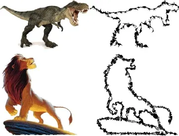
Fig.12 Results with patterns in different groups from our pattern library.Left:reference images,right:collage results.
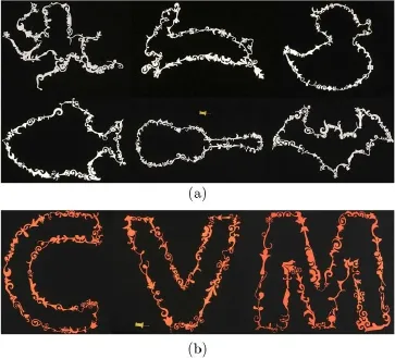
Fig.13 Physical results fabricated by an FDM 3D printer(a)and a laser engraving machine(b).
6 Conclusions and future work
Wehave tackled theproblem ofgenerating manufacturable pattern collages along a given boundary. Our proposed method automatically computes an initial packing of the patterns and further optimizes the distribution and connectivity of the pattern units after user interactive tuning of their placement.The results can be fabricated directly by 3D printing or laser cutting.
One limitation of the current method is that if the input shape has many fi ne features,such as a feather,the collage result cannot preserve these features.
For further improvement,we would like to consider the geometry of the boundary when generating the initial packing of the elliptic proxies.The current matching between elliptic proxies and pattern units is based on geometry only;however,we hope to consider high-level semantic features of the patterns in future work.
Furthermore,we wish to investigate collage algorithms along 3D curves as future work.It is also worth investigating adding further functionality to the interactive design step.
Acknowledgements
We thank all anonymous reviewers for their valuable comments and constructive suggestions.This work was supported by grants from National Natural Science Foundation of China(NSFC)(No.61572291),the Young Scholars Program of Shandong University(YSPSDU),and the Open Project Program of the State Key Laboratory of Virtual Reality Technology and Systems,Beihang University(VRLAB2019A01).
Open AccessThis article is licensed under a Creative Commons Attribution 4.0 International License,which permits use,sharing,adaptation,distribution and reproduction in any medium or format,as long as you give appropriate credit to the original author(s)and the source,provide a link to the Creative Commons licence,and indicate if changes were made.
The images or other third party material in this article are included in the article’s Creative Commons licence,unless indicated otherwise in a credit line to the material. If material is not included in the article’s Creative Commons licence and your intended use is not permitted by statutory regulation or exceeds the permitted use,you will need to obtain permission directly from the copyright holder.
To view a copy ofthis licence, visit http://creativecommons.org/licenses/by/4.0/.
Other papers from this open access journal are available free of charge from http://www.springer.com/journal/41095.To submit a manuscript,please go to https://www.editorialmanager.com/cvmj.
杂志排行
Computational Visual Media的其它文章
- Unsupervised natural image patch learning
- Deep residual learning for denoising Monte Carlo renderings
- Fast raycasting using a compound deep image for virtual point light range determination
- Object removal from complex videos using a few annotations
- Automatic route planning for GPS art generation
- Single image shadow removal by optimization using non-shadow anchor values
