Fast raycasting using a compound deep image for virtual point light range determination
2019-02-17JesseArcherGeoffLeachandPyarelalKnowles
Jesse Archer(),Geoff Leach,and Pyarelal Knowles
Abstract The concept of using multiple deep images,under a variety of different names,has been explored as a possible acceleration approach for fi nding raygeometry intersections.We leverage recent advances in deep image processing from order independent transparency for fast building of a compound deep image(CDI)using a coherent memory format well suited for raycasting.We explore the use of a CDI and raycasting for the problem of determining distance between virtual point lights(VPLs)and geometry for indirect lighting,with the key raycasting step being a small fraction of total frametime.
Keywords deep image;indirect lighting;raycasting
1 Introduction
Recently,the use of multipledeep imageshas been explored as an alternative to abounding volume hierarchy,the most common acceleration approach for raycasting.Deep images store multiple per-pixel fragments which include color and depth information,compared to 2D fl at images which store only a single color value. Deep images are a view-dependent discretized representation of scene geometry,and a complete,nearly view-independent representation for the purpose of raycasting can be achieved using many deep images from different directions-which we call acompound deep image(CDI).
Previous approaches have found that building few deep images is fast but slow to raycast due to the need to step between different deep image pixels and directions.Fast raycasting requires many deep images from different directions,which allows a ray to be contained in a single pixel with fragments representing geometry intersections.While raycasting such a CDI is fast,previous approaches to building the deep images have been relatively slow and non-realtime,typically using memory incoherent per-pixel linked lists.We present a realtime approach for building a CDI using per-pixel linearised arrays,a memory coherent alternative to linked lists which offers faster raycasting.
ThispaperexploresfastCDIbuildingand raycasting for the problem of range determination using ray-geometry intersections for indirect lighting usingvirtual point lights(VPLs),as shown in Fig.1.The primary challenge for realtime rendering of VPLs is determining which VPL applies to what geometry.Recent realtime VPL techniques either assume lights have in fi nite range and restrict their contribution to geometry using imperfect shadow maps,or limit ranges randomly as unshadowed stochastic VPLs.Restricting the range of each light allows rapid building of a light grid which can be applied to geometry.We show that ranges can be estimated by casting multiple rays per-VPL to nearby geometry.This approach is fast for thousands to millions of VPLs,with realtime raycasting of up to tens of millions of rays.
While range determination has potential to improve visual quality over randomly assigned light ranges,this work omits detailed visual comparisons with other VPL techniques.We instead provide a basic visual comparison with ground-truth path tracing showing that our work gives similar results to single bounce path tracing but with some visual artifacts.The primary focus of this work is improved performance of the CDI building and raycasting steps.We show that,while slower than assigning random light sizes,the raycasting step is only approximately 1%of total frametime.
2 Related work
Deep images are primarily used in compositing and transparency,but have recently been applied to various lighting problems.Raycasting using deep images with three deep image directions is presented in Refs.[1,2]but requires rays to step between pixels.CDIs have been explored for global illumination[3,4]but with non-realtime results,or requiring precomputing which is unsuitable for dynamic scenes.In general,using fewer directions is faster to build while using more directions reduces the need to step between pixels and thus is faster to raycast.
The use of screen-space deep images[5]and unstructured surfel clouds[6]for raycasting has also been presented.However,our focus is raycasting deep images of full object-space scene geometry.
Advances in fast building of deep images in real time have primarily been presented fororder independent transparency,requiring both a capture and a sorting stage.Capture using linked lists and linearised arrays has been compared[7,8].Linked lists have smaller capture time while arrays are faster to sort and process.Fast sorting of full fragment list data relies on using blocks of GPU registers[9,10]and more recently GPU instruction caching[11].
Indirect lighting is a well known problem;instant radiosity[12]was the fi rst proposed fast VPL technique.Single bounce VPLs are generated fromre fl ective shadow maps(RSMs)[13]which record light bounces from a primary light source.Restricting the contribution of each VPL to nearby visible geometry is achieved in real time either usingimperfect shadow maps[14-16],or approximated stochastically by assigning random light ranges or randomly culling unshadowed VPLs for diffuse[17,18]and glossy lighting[19].
Light grids are a well established approach for rendering scenes with many lights where the range of each light is known and fi nite.Various approaches for building both 2D[20-22]and 3D[23,24]grids have been explored.This work uses thehybrid lightingapproach[25]for building a 3D grid;linearised arrays were similarly found to offer faster processing of light data than linked lists.
3 CDI building and raycasting
3.1 CDI building
A compound deep image(CDI)is a collection of deep images from different directions with each deep image stored sequentially using linearised arrays.Many approaches exist for determining unique deep image directions,with previous work sampling using a unit cube from three or more directions,or uniformly distributing directions on a unit sphere.This work samples deep image directions from a hemisphere using spherical coordinates as shown in Fig.2.Only the top hemisphere is needed as the bottom is indexed by reversing a given ray’s direction.Other sampling approaches have previously been used such as recursive zonal equal-area partitioning[4]and uniformly sampling a unit cube[3].
Each pixel in a deep image represents a speci fi c ray in that deep image’s direction.The fragment list for the pixel then gives all the geometry intersected by the ray.The ray for a given object-space position is determined by computing the deep image’s screenspace pixel.
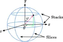
Fig.2 Direction vector using spherical coordinates.
A brute force approach for building a CDI rerasterizes geometry for each unique direction as in previous work.However,this approach is expensive for hundreds of directions.We instead use a well known approach forgeometryvoxelization by rasterizing geometry once and saving fragment data for many directions.
Geometry is rasterized with the camera oriented along thezaxis.The normal vector of each triangle is checked in the geometry shader andx,y,zcomponents are swizzled for triangles primarily facing along thexoryaxes to ensure each triangle is instead primarily facing along thezaxis.Unswizzled object-space positions are passed to the fragment shader.Per-direction orthographic modelviewprojection matrices are iterated and multiplied with the fragment’s position,yielding unique per-direction fragments which are added to the appropriate deep images.See Fig.3.
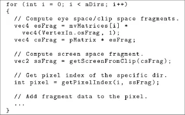
Fig.3 Computing unique per-direction fragments in the fragment shader from object space positions.
Many geometry voxelization approaches require conservative rasterization to ensure all geometry is represented.We fi nd that for the problem of VPL range determination,a non-conservative representation suffices,reducing both memory usage and deep image build time.Any missing geometry can cause some VPLs to have larger ranges than needed,which is offset by taking an average length of multiple ray directions.
Sampling geometry primarily facing along thezaxis maximises the number of geometry samples generated in the fragment shader. This causes redundant fragment data to be added for deep image directions where geometry is side-on or at an angle where fewer samples are needed,increasing overall CDI memory usage by up to 25%.
Fast raycasting using deep images relies on reading fragment data coherently,so arranging fragment data into appropriate coherent buffers in memory is critical for fast processing on the GPU.Two possible approaches are linked lists and linearised arrays.
Previous deep image raycasting techniques typically used per-pixel linked lists where fragment data can be written in-place as geometry is rasterized.This approach offers fast build time as fragment data is written sequentially during rasterization,but at the expense of slower raycasting,as following the next pointers for each linked list leads to scattered memory reads.
Linearised arrays require two buffers as shown in Fig.4.Unlike linked lists,in which fragment data can be anywhere,fragment data in linearised arrays for a given pixel is coherent,with all fragments for a given pixel stored contiguously.Linearised arrays are slower to build than linked lists but faster to raycast.
Building a deep image in this format is summarised as follows,based on Ref.[26]:
·Initialise a buffer of per-pixel counts to zero.
·Render geometry and atomically increment counts in the fragment shader.
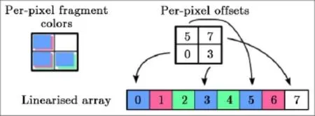
Fig.4 Per-pixel blue/red/green,blue/green,and blue/red fragment colors stored in linearised arrays.
·Compute per-pixel offsets from counts using parallel pre fi x sums.
·Allocate fragment data buffer of size given by fi nal offset.
·Re-render geometry,storing fragments in locations determined by atomically incrementing offsets.
Traversing a pixel’s fragment data requires reading the index offset and number of fragments,then reading the fragment data sequentially.Example code is given in Fig.5 for the three main steps of computing per-pixel counts,adding fragment data to,and traversing the linearised array.The same buffer is used for both fragment counts and offsets.Not shown is computing offsets using a parallel pre fi x sum scan,which is described in Ref.[27].
A limitation of using linearised arrays is that geometry must be rasterized twice as opposed to linked lists where it is rasterized once.For complex scenes where rasterization is a bottleneck,this can cause capture time for arrays to be up to twice as long as for linked lists.Despite this,linearised arrays have better overall performance,as the CDI is built only once but read many times,and the coherent memory reads of linearised arrays are much faster than the scattered memory reads of linked lists.
Fast raycasting requires each pixel’s fragment list to be in depth sorted order.Fast per-pixel fragment sorting depends on maximising use of registers,the fastest available GPU memory. Using registers requires hard coding a sort network with all compareand-swap operations explicitly de fi ned[10].We use an unrolled bitonic sort network which also provides improved instruction caching[11].
As available per-thread registers are limited,long lists are sorted in blocks.Each block is sorted using a hard-coded sort network followed by ak-way merge in local memory of the sorted blocks[9].
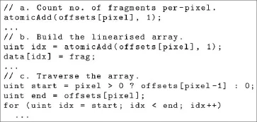
Fig.5 Adding a fragment to and traversing a pixel’s linearised array.
Finally,fragment data is written back to global memory after sorting.This sort approach is very fast,with reading from and writing back to global memory being up to 90%of the total sort time.Sorting is thus primarily dominated by memory bandwidth.
An example of part of the fi nal CDI rendered transparently is shown in Fig.6 where the Atrium scene is shown from many different directions,each represented as a separate deep image.Note that extra fragments are present for some geometry in different directions,leading to overlapping triangles.As geometry is captured from a single rasterization,the same viewport size is used for all deep images,which is large enough to contain the entire scene from any direction.
3.2 VPL range determination
We apply a CDI to the problem of range determination of VPLs using broadly the following steps.
·Capture and sort the CDI.
·Render g-buffer from camera’s perspective.
·Render RSM from primary light’s perspective,giving VPL positions.
·Build buffer of unique VPLs,raycasting using the CDI to determine VPL ranges.
·Build light grid from the VPL buffer.
·Apply the light grid to the g-buffer,giving the fi nal result.
After building the CDI,a global buffer of unique VPLs is built.Scene geometry is rendered from the light’s perspective to an RSM,giving VPL positions and colors.To avoid oversampling geometry close to the light,we use a mipmapped RSM and choose positions from higher mipmap levels based on distance to light source. Other approaches for choosing optimal VPL positions from an RSM have been explored but this issue is not the focus of this work.
As VPL positions are calculated,the distance to nearby geometry is determined by raycasting through the previously built CDI.The primary VPL direction is given either by the re fl ected light direction or the surface normal.Six rays per-VPL are cast,one in the primary direction and fi ve oriented around it.
Each ray indexes the CDI using the closest matching direction. The light’s position then determines the pixel matching that speci fi c ray.Distance from the light to geometry is found by stepping through the pixel’s fragment list from the beginning until a fragment after the light’s position is reached.This linear stepwise search is used as a binary search was found to be slower.The difference in depth between the fragment and the light gives an approximate range for the given ray.Fragments are stepped in reverse order for rays in the matching opposite direction.After raycasting,a sphere for the VPL is created with radius of the either the average or maximum distance to geometry.

Fig.6 Part of a CDI showing the Atrium scene as multiple deep images in different directions.
Scenes typically require many small lights and few large lights.We keep most small lights,discarding those too small to noticeably affect the scene and most large lights.Each non-discarded VPL is atomically added to a global VPL buffer storing position,color,and size.
After building the CDI and determining light sizes we usehybrid lighting[25]as mentioned in Section 2 to build and apply the light grid from the global VPL buffer. 2D light outlines are rasterized at coarse resolution with front and back per-tile depths determined using a line-sphere intersection test.The light’s data is then added to all 3D grid cells between the front and back depths for the 2D tile.Light grid data is stored using the same linearised array format as for the deep image,which was similarly found to be faster than using linked lists.A depth mask is built from the g-buffer to avoid adding lights to grid cells that contain no geometry.
As VPLs are not necessarily uniformly distributed in the scene,to prevent some parts of the scene appearing too dim or too bright,per-pixel lighting is adjusted proportionally to the number of applicable VPLs.Lighting is applied using the Cook-Torrance BRDF[28]which is suitable for diffuse and glossy materials.
Other techniques for spawning and applying VPLs with and without light grids have been discussed but are not our primary focus,instead being left for future work.Shadows from the primary light source are calculated separately and not included in performance measurements.
4 Results
We compare performance of indirect lighting using VPLs for the two scenes shown in Fig.1. The fi rst scene is the Sponza Atrium with approximately 280,000 triangles and the second is the Rungholt outdoor town scene with approximately 7 million triangles.These scenes are available from Ref.[29].The test platform was an NVIDIA GeForce GTX 1060,driver version 390.25.Scenes were rendered at HD(1920×1080)resolution.Time is reported in millisecond.
The primary focus of this work is determining the cost of building and raycasting the CDI for VPL range determination in the context of indirect lighting,with chosen VPLs being added to a light grid.As stated previously,other techniques for choosing and applying VPLs both with and without light grids have been presented and combining range determination with these techniques is left for future work.
Results for the full VPL rendering approach are shown in Table 1 where raycasting is shown in bold and is the fastest VPL rendering step.The CDI uses 169 directions at 64×64 resolution which represents a hemisphere of 13×13 stacks and slices.Raycasting is performed when building the global VPL buffer shown in bold to estimate light sizes and takes approximately 1%of the total frametime.The RSM is rendered at 256×256 resolution and contains 65,536 potential VPLs.Only 20,000 VPLs are typically used to avoid oversampling geometry close to the light source,which after raycasting and discarding based on size are reduced to 2000 and 8000 VPLs for the Atrium and Rungholt scenes respectively.
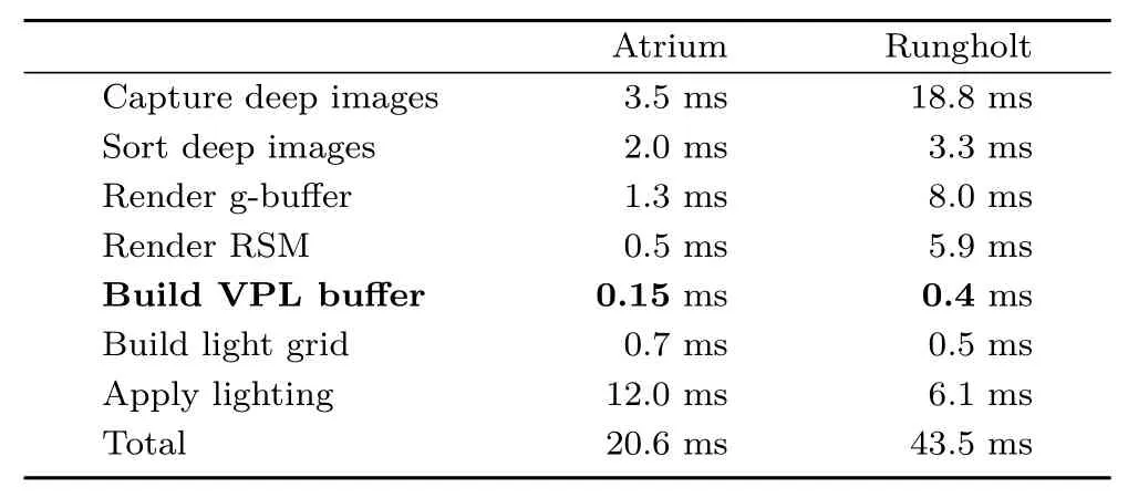
Table 1 Time for each step of VPL rendering
There is little overhead for computing many directions,as shown in Table 2,which compares building the CDI with an increasing number of directions. The Atrium scene is dominated by memory writes but processing remains fast even for more than one hundred directions.There is little difference in performance for the Rungholt scene which is dominated by geometry rasterization being performed twice,once for per-pixel counts and once to write the fragments.For both scenes,total build time scales linearly with the number of directions.
Our CDI approach that builds all directions simultaneously is 20×to 100×faster than a brute force approach that builds directions separately.For 169 directions our approach takes 5.5 and 22.1 ms to build the CDI for the Atrium and Rungholt scenes respectively,while a brute force approach takes 121.3 and 2295.8 ms,with no difference in the fi nal indirect lighting result.
Table 3 shows the cost of raycasting for an increasing number of lights.Time to cast six rays per-VPL to estimate size for the Atrium and Rungholt scenes is compared with time to assign a random sizeto each light.Lights are spawned for all RSM pixels and none are discarded.

Table 2 CDI build time

Table 3 Raycasting time for Atrium and Rungholt scenes,versus assigning random size VPLs
Raycasting time increases nearly linearly with the number of rays,and is approximately 10×slower than assigning random ranges.While this difference is signi fi cant,it remains fast for thousands to millions of VPLs and as shown in Table 1,it is only a small percentage of total frametime.While slower than randomly assigning light ranges,raycasting allows indirect lighting using fewer lights than stochastic approaches where many more lights are required to ensure enough VPLs cover the necessary geometry.
Complexity of geometry has little impact on raycasting performance,with the Rungholt scene being no more than 10%slower to raycast than the Atrium.While the Rungholt scene has more than 20×the number of triangles,CDIs for the two scenes are approximately the same size,at 18 MB for 169 directions,which is insigni fi cant compared to the total memory available on most modern GPUs.Fragment list lengths for the Rungholt scene are typically only slightly longer than the Atrium and thus only slightly slower to raycast.
At the highest tested resolution of 2048×2048,approximately 25 million raycasts are performed in 20 ms,equivalent to raytracing an HD(1920×1080)image with 12 rays per-pixel.
For the Atrium scene,it takes 5.5 ms to capture and sort the CDI,which compares favourably with other CDI techniques.For the Atrium scene,thedeterministically layered depth mapsapproach[4]takes 373 ms for both building and computing ambient occlusion,and more than 1000 ms for computing indirect lighting,although they do not specify how much time is speci fi cally dedicated to building and raycasting.Their results were reported using a GTX780 Ti to render at 800×800 resolution with 512 deep images of 50×50 resolution.Older CDI work[3]reports 60 ms for calculating indirect lighting of the Atrium with a precomputed CDI.
Multiview and multilayer interactive ray tracing[2]renders three directions rather than many and takes 10 ms build time for the Atrium using a GTX780 Ti at 720×480 resolution with deep images rendered at 480×480 resolution.Again,our build approach is faster given the difference in hardware.
The ground-truth Rungholt outdoor town scene rendered using path tracing with 128 per-pixel samples is shown in Fig.7,with zero bounce and one bounce respectively.Our approach gives similar results to one bounce path tracing but with visual artifacts where some areas of the scene are darker or brighter than the ground-truth rendering.
Brighter areas are caused by light bleeding from unshadowed VPLs that affect more geometry than necessary while darker areas are caused by parts of the scene being undersampled from the light’s perspective in the RSM.Addressing these artifacts requires calculating shadows using imperfect shadow maps and a better sampling approach for spawning VPLs.Range determination of VPLs should improve performance of existing shadow map approaches by reducing the number of maps that need to be tested per-pixel.

Fig.7 Rungholt scene rendered using path tracing with zero and one bounce.
5 Conclusions
This work has presented a CDI approach that offers fast build time with little memory overhead.The linearised array format used is ideally suited for raycasting due to fragment list memory coherence,even for millions of VPLs.
We use CDIs speci fi cally for building a VPL grid.Previous papers have explored CDIs for ray and path tracing,and applying our coherent CDI structure should similarly improve performance.
Using the CDI to build a light grid shows similar results to one bounce path tracing but with some visual artifacts.Addressing these requires combining imperfect shadow maps and a better sampling approach for spawning VPLs.
Electronic Supplementary MaterialSupplementary material is available in the online version of this article at https://doi.org/10.1007/s41095-019-0144-1.
Open AccessThis article is licensed under a Creative Commons Attribution 4.0 International License,which permits use,sharing,adaptation,distribution and reproduction in any medium or format,as long as you give appropriate credit to the original author(s)and the source,provide a link to the Creative Commons licence,and indicate if changes were made.
The images or other third party material in this article are included in the article’s Creative Commons licence,unless indicated otherwise in a credit line to the material. If material is not included in the article’s Creative Commons licence and your intended use is not permitted by statutory regulation or exceeds the permitted use,you will need to obtain permission directly from the copyright holder.
To view a copy ofthis licence, visit http://creativecommons.org/licenses/by/4.0/.
Other papers from this open access journal are available free of charge from http://www.springer.com/journal/41095.To submit a manuscript,please go to https://www.editorialmanager.com/cvmj.
杂志排行
Computational Visual Media的其它文章
- Unsupervised natural image patch learning
- Deep residual learning for denoising Monte Carlo renderings
- Object removal from complex videos using a few annotations
- Manufacturable pattern collage along a boundary
- Automatic route planning for GPS art generation
- Single image shadow removal by optimization using non-shadow anchor values
