A simplified simulation method of friction pendulum bearings
2019-01-17WangYanhuaFengYanWuJing
Wang Yanhua Feng Yan Wu Jing
(Key Laboratory of Concrete and Pre-Stressed Concrete Structures of Ministry of Education, Southeast University, Nanjing 210096, China)
Abstract:In order to improve the computation efficiency and simulation accuracy, a novel simplified simulation method for friction pendulum bearing (FPB) is proposed. The behavior of FPB was analyzed based on the stress characteristics of the slider of FPB. Then, a novel simplified FPB model with a single pendulum and a nonlinear spring was established. The mechanical behavior of the simplified model was analyzed and it conformed well to the basic requirements of FPB. Furthermore, shaking table tests of a concrete slab block structure isolated by four FPBs were carried out, followed by finite element simulations of the test using the proposed simplified model. Three waves and eleven loading scenarios were selected in the test. The results show that the overall trend of the relative displacement time-history curves, the horizontal acceleration time-history curves and the vertical acceleration time-history curves from the numerical simulation match in a good manner with those obtained from the tests. Specifically, it is found that the difference of the peak value within these curves between the simulation and test results is less than 15%, which means that the proposed simplified model can be used to simulate the FPB behaviors under dynamic loadings with acceptable accuracy for engineering purposes.
Key words:friction pendulum bearing (FPB); simplified model; finite element modelling; shaking table test
The design and simulation of isolation devices is one of the most important aspects for structure isolation technologies. In general, there are three main types of isolation bearings for earthquake engineering: spring type isolation bearings, sliding isolation bearings and hybrid isolation bearings. Among these bearings, the friction pendulum bearing (FPB) for hybrid isolation gains the most attention. FPB, first developed by Zayas et al.[1]from the University of California, Berkeley, can be used for both energy dissipation and resetting. Moreover, FPB is gradually being used more in seismic design of building structures and bridges for its advantages such as a high vertical bearing capacity, low maintenance cost and no extra need for fire and aging prevention[2].
Since FPB was first proposed, researchers all over the world have paid much attention to it and have done many investigations[3-6]. Currently, the most frequently used methods to model FPB behavior are the equivalent linearization model, bilinear model and Wen model[7-9]if no solid model is used. However, there are still many issues to be solved for FPB, such as the low computational efficiency with longer computing time of the solid model, a shorter computational time but lower accuracy of other simplified models, especially the impossibility for the Wen model to simulate the slight vertical elevation of the upper structure due to the oscillation in the circular arc of the FPB. So, how to find a simple model but with reasonable accuracy to simulate its mechanical behavior is the key to the friction pendulum bearing.
In this study, a simplified simulation method in which a pendulum and a nonlinear spring are used is proposed. Finite element simulations as well as shaking table tests were adopted in this paper to demonstrate the simplicity and the accuracy of the proposed model. Also, the comparisons between the new simplified method and the Wen model in practical projects verified its advantages in simulating large swings, resetting and viscous behaviors.
1 The Simplified Model of FPB
1.1 Mechanical mechanism of FPB
A FPB consists of a lower plate with a spherical concave surface, an articulate slider and an upper plate with a slider chamber. The slider is generally coated with low-friction sliding materials as shown in Fig.1.

Fig.1 Schematic diagram of FPB
A FPB can be regarded as a slider that makes a simple pendulum movement. Fig.2 shows the stresses applied on the slider in the process of sliding.

Fig.2 Stresses applied on the slide block
In Fig.2, the radii of the spherical concave surface and the sliding surface are bothRand the two surfaces touch closely during the movement.Dis the horizontal distance of the slider movement (positive to the right);θis the angle rotation between the slider and the vertical symmetric axes of the sliding surface (counterclockwise is positive);Wis the vertical load applied to the slider from the superstructure;Nis the support force of the sliding surface to the slider;fis the frictional force between the slider and the sliding surface andFis the horizontal seismic action of the upper structure loaded on the slider. Considering the force equilibriums in the horizontal and vertical directions, we can obtain the following equations:
N=Wcosθ
(1)


(2)
Furthermore, the moment equilibrium at pointOcan be described as
FRcosθ-fR-WD=0
(3)
Thus, the horizontal force of the sliderFcan be derived as follows:
(4)
It should be noted that the value ofθis generally so small that the value of cosθapproximately equals 1.
(5)
Eq.(5) shows thatFcan be seen as a combination of two parts, i.e., a restoring force and a friction force[10].
1.2 The simplified model of FPB
As mentioned above,the horizontal forceFcan be seen as the combination of a restoring force and a friction force. Therefore, a simplified model of FPB, in which a simple pendulum (restoring force) and a nonlinear spring (friction force) are used, can be established, as shown in Fig.3.

Fig.3 Simplified model of FPB
Since the simple pendulum can be seen as a two-force rod in the simplified model, only the axial force needs to be taken into consideration. The length of pendulum is equal to the radius of the curvature of the sliding surface. In the following, a perfectly rigid-plastic model is used for the nonlinear spring with a yield force equal to the sliding friction force applied on the slider.
As shown in Fig.3, the sliding of the FPB slider is simulated by the swing of the simple pendulum in the simplified model. PointHat the lower end of the pendulum can be regarded as the slider of FPB;Wis the vertical load applied on the slider by the upper structure andTis the axial tension of the pendulum on the slider. Based on the force equilibrium and the analysis above,Tis equal toWcosθand it is also equal toN. Therefore,Tcan be used to simulate the support forceN.fis the counterforce applied by the nonlinear spring to the slider and it is used to simulate the friction force on FPB. Then following equation can be obtained from the requirement of the moment equilibrium regarding pointO.
FRcosθ-fRcosθ-WD=0
(6)
Whenθis relatively small, the horizontal shear forceFis obtained as
(7)
It can be shown from Eq.(7) that the shear force derived from the simplified model is exactly the same as that derived in Eq.(5), which means that the proposed simplified FPB model matches well with the mechanics of FPB.
2 Finite Element Model for the Simplified FPB Model
In the following, the simplified FPB model is simulated by the finite element software ABAQUS. In the simulation, the pendulum is modeled by truss elements, which means that there is no bending but axial forces during its deformation. As mentioned, the length of the pendulum is assigned as the curvature radius of the sliding surface and the linear elastic material is adopted. Practically, since there is almost no vertical deformation present in the FPB, a large value should be taken to ensure a minimal axial deformation for the elastic modulus of the pendulum, such as 9×10⁹MPa in this simulation. Since there are no ideal rigid-plastic materials in the ABAQUS default material library, the nonlinear spring in the simplified model is modeled by a truss element, which is of great convenience in the simulation by using the ideal elastoplastic material with a large elastic modulus. The yield strength of the ideal elastoplastic material is equal to the sliding friction of the slider. The simplified model in ABAQUS is shown in Fig.4.

Fig.4 Simplified model in ABAQUS
3 Shaking Table Tests of FPB Isolated Structure
3.1 FPB isolated structure
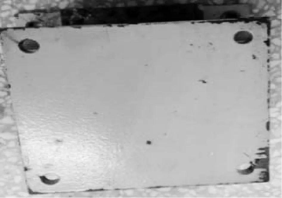
The shaking table tests were carried out with a concrete slab block isolated from four FPBs at the bottom. The schematic diagram of the shaking table test is shown in Fig.5 and the concrete slab is shown in Fig.6. Four steel pipes are evenly embedded in the four corners of the concrete slab for further bolt connections to the bearings. The dimension of the concrete slab is 2 m×2 m with a depth of 0.4 m. The density of concrete is 2.5 t/m3and the

Fig.5 Schematic diagram of shaking table test
selfweight of the slab is then 40 kN. Therefore, the weight of the slab is evenly distributed to the four bearings during the test, i.e., 10 kN for each bearing.
The friction pendulum bearings used in the shaking table tests are shown in Fig.7 and their parameters are listed in Tab.1. Previous studies show that the friction coefficient of FPB is mainly determined by the speed and pressure applied on the slider[11]. If the pressure is fixed, the friction coefficient will increase with the increase of the sliding speed within a certain range. When the sliding speed increases to a certain value, the friction coefficient will be kept as a constant, which is 0.065 (upper pressure is 10 kN).

(a) (b)

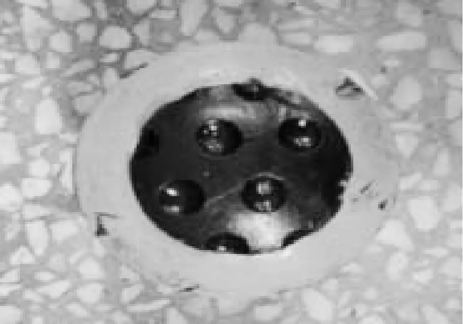
(c) (d)Fig.7 FRBs used in the tests. (a) Front view;(b) Vertical view;(c) Sliding surface of lower plate;(d) Slider

Vertical bearing capacity/ kNRadius of slip surface/mmDesign displacement/mm60 63±15
3.2 Test set-up
The tests were carried out on a 4 m×6 m seismic shaking table in the Civil Engineering Experimental Center at Southeast University Jiulonghu campus. During the tests, one low-frequency seismic geophone (941-B) and four three-direction accelerometers (TST 120T100) were used to measure acceleration. In addition, four rod-type displacement transducers (TST-161) and a wire-type displacement transducer (ASM-50 mm) were used to measure displacement.
The arrangement of the displacement and acceleration sensors are shown in Fig.8, in which DL represents a wire-type displacement transducer; D1 to D4 represent rod type displacement transducers; A1 to A4 represent three-direction accelerometers and 941 represents a 941-B type low-frequency vibration pickup.

Fig.8 Layout of sensors in shaking table tests
One end of DL is fixed on the shaking table and the other is connected to the concrete slab. It is used to measure the relative horizontal displacement between the concrete slab and the vibration table, namely the relative sliding displacement of FPB, as shown in Fig.9(a). D1, D2 and D3 are assigned to measure the absolute displacement of concrete slab and D4 measures the absolute displacement of the shaking table. The accelerometers A1 to A4 are arranged on the upper deck of the four FPBs under the concrete slab respectively, as shown in Fig.9(b), to measure the acceleration in the three directions of the support plate on the FPBs. The 941-B type pickup is arranged on the upper surface of the concrete slab to measure the vertical acceleration of the concrete slab.


(a) (b)Fig.9 Layout of measuring instruments. (a) Wire-type displacement transducer; (b) Three-direction accelerometer
3.3 Loading conditions
Three different earthquake motions, i.e., Kobe, Trinidad and Sakaria waves, were selected in the tests. The peak acceleration of each wave was set to be 0.15g, 0.20gand 0.25g. In addition, white noise tests were carried out to sweep the isolated structure to check whether the mechanics and bearing capacity of the isolated structure were in good condition or not. Therefore, in total, eleven loading conditions were adopted during the tests, as shown in Tab.2.
3.4 Finite element simulation of the tests
The experimental process was simulated and analyzed using the finite element software ABAQUS, in which the FPB in the isolated structure was modeled by the proposed simplified model[12-16]. The simplified structure of
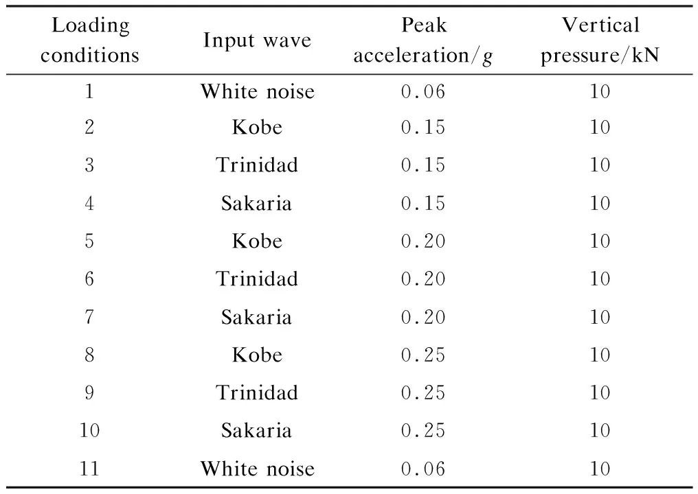
Tab.2 Loading conditions of the shaking table tests
the FPB model is shown in Fig.10. The concrete slab is modelled by the simplest linear elastic material with an elastic module of 3×10⁴N/mm2. The length of the single pendulum during simulation is set to be the same as that in the tests (63 mm). According to the tests, the upper pressure of FPB is 10 kN and the friction coefficient is 0.065. Thus, the sliding friction force of sliding block is 0.65 kN based on the Coulomb law of friction. Therefore, the yield stress of the nonlinear spring in the simplified model is set to be 0.65 kPa.
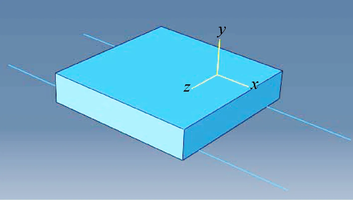
Fig.10 Finite element model of the FPB isolated structure
3.5 Comparisons between tests and finite element simulation
3.5.1 Results of white noise sweeping
The first-order frequencies of the structure before and after the tests are found to be constant 2.5 Hz by white noise sweeping. It indicates that the isolated structure worked very well and did not change after excitations.
3.5.2 Comparison of relative displacement time-history curves
Fig.11 shows the results of the displacement transducers D1 and D3 subjected to the loading condition 2. It can be seen from the figure that the absolute displacement time-history curves of the two measuring points are almost coincident under this condition. Other loading conditions share a similar conclusion with condition 2. Therefore, it can be considered that there is no in-plane torsion but merely horizontal motion of the concrete plate occurred in the direction of the vibration of the shaking table.
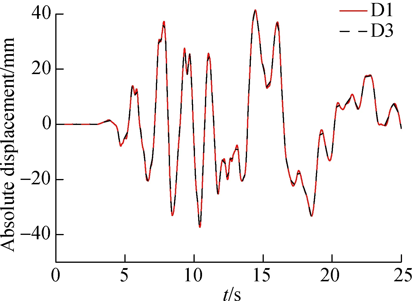
Fig.11 Absolute displacement time-history curves of D1 and D3 in condition 2
Fig.12 shows the comparison of the relative displacement time-history curves between the tests and the finite element simulations for some loading conditions. The comparison of peak (absolute) values is shown in Tab.3.
It can be seen from Fig.12 that when the peak value of the seismic wave is 0.20gand 0.25g, the finite element

(a)

(b)

(c)Fig.12 Comparison of relative displacement time-history curves. (a) Condition 3;(b) Condition 6;(c) Condition 10
Tab.3Comparison of peak values in relative displacement time-history curves

Loading conditionsPeak value of relative displacement/mmExperimentSimulationError/% 34.994.3313.166.787.064.1107.688.227.0
simulation results correspond well with the experimental values, and the peak values and phases are also close. When the peak acceleration is 0.15g, the two relative displacement curves are in good agreement with each other except for a few extremums. There are two reasons to explain for this phenomenon: First, when the peak acceleration is 0.15g, the relative displacement of FPB is too small to fully demonstrate its mechanical properties, which results in that the hysteresis curve is rather messy and the differences between the test and the simulation cannot be ignored . Secondly, as shown in Section 3.1, the coefficient of the friction increases with the increase in sliding speed within a certain range. The friction coefficient used in the simulation is a constant value which is greater than that at a low speed. This can explain the differences between the finite element simulation results and experimental values in weak excitations. However, at the peak point of the seismic wave when the FPB has reached a certain sliding velocity, the friction coefficient of the simplified model is close to the actual value, which results in the displacement consistency of the model and actual test.
It can be seen from Tab.3 that the peak-value differences between the experiment and the simulation are less than an acceptable level of 15%. This means that the proposed simplified model can be used to simulate the relative displacement of FPB under dynamic loading.
3.5.3 Comparison of horizontal acceleration time-history curves
A1 to A4 are used to measure the horizontal acceleration of FPB. It is found that the values of the four accelerometers are very close, indicating the synchronous movement of the four supports. The data obtained by A2 are taken to make comparisons with the finite element simulation results. Fig.13 shows a comparison of the horizontal acceleration time-history curve under loading conditions 3 and 8 and the comparison of the corresponding peak (absolute) values is shown in Tab.4.
As can be seen from Fig.12, the overall trend of the experimental values and the simulated values are in good agreement except for some extreme points, As shown in Tab.4, the differences of the peak values between the test and the simulation are very small and the error is within 10%. This proves that the proposed simplified model can be used to simulate the horizontal acceleration responses of FPB under dynamic load excitation with reasonable accuracy.

(a)

(b)Fig.13 Comparison of horizontal acceleration time-history curves. (a) Condition 3;(b) Condition 8
Tab.4Comparison of peak values in horizontal acceleration time-history curves

Loading conditionsPeak value of horizontal acceleration/gExperiment SimulationError/%Condition 30.105 50.097 97.20Condition 80.182 30.171 06.20
3.5.4 Comparison of vertical acceleration timehistory curves
Fig.14 shows the comparison of the vertical acceleration time-history curves between the tests and simulation results under several loading conditions. The corresponding comparison of peak values (absolute values) is shown in Tab.5. As can be seen from Fig.14, the test and simulation results only match well at peak points, and the overall trend is that the simulation values are lower than those from the tests. The proposed model fails to capture the acceleration responses under low excitations as a result of the great friction coefficient used in the simulations. However, it is worth noting that, as can be seen from Tab.5, the peak errors between the tests and the simulations are still less than 15%. In combination with the observations in the above sections, it can be concluded that the proposed simplified model can be used to simulate the mechanical behavior of the superstructure isolated by FPBs.
4 Comparison of the Simplified Model with the Wen Model of FPB
Two four-storey isolation structures, respectively, with four new simplified models and Wen models are established,

(a)

(b)
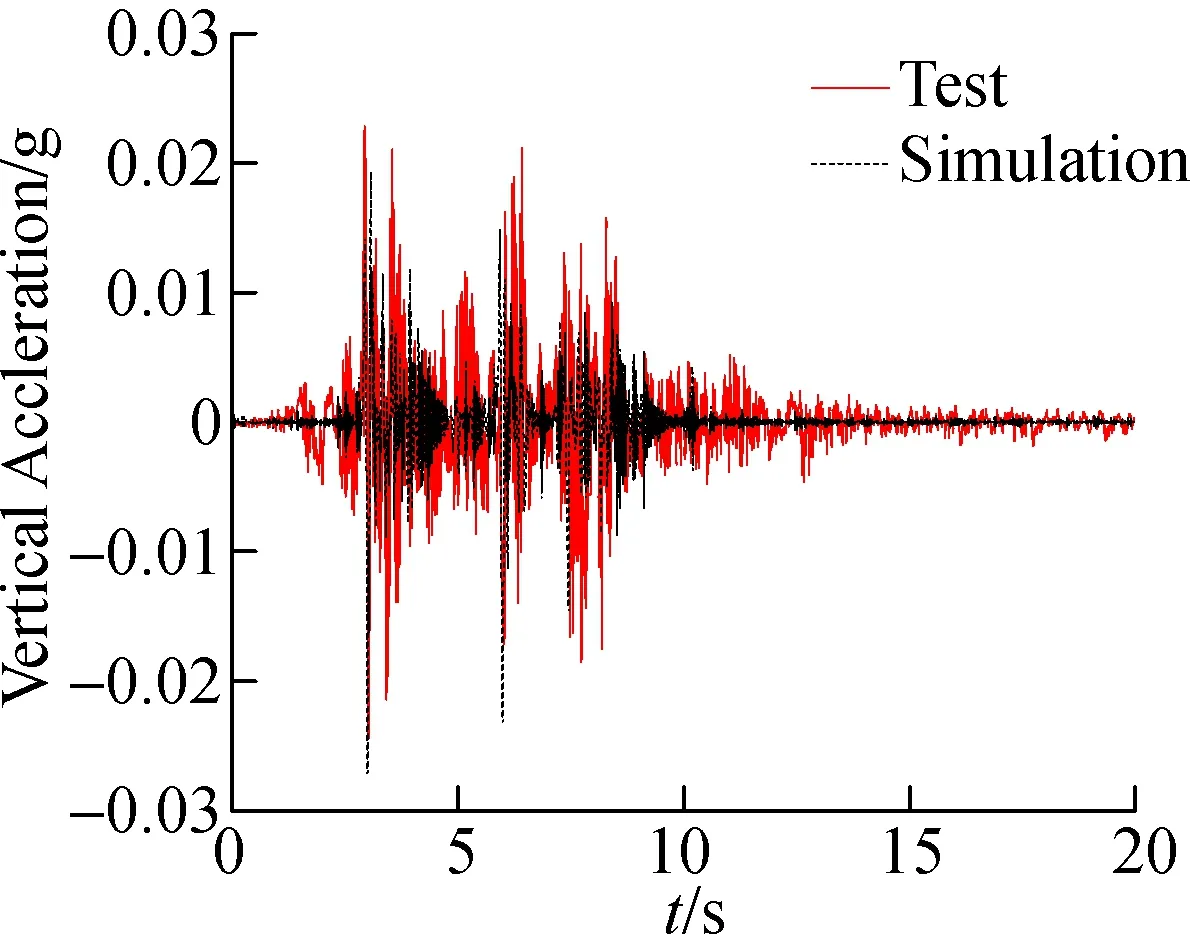
(c)Fig.14 Vertical acceleration time-history curves of FPB.
(a) Condition 5;(b) Condition 8;(c) Condition 10
Tab.5Comparison of peak values in vertical acceleration time history curves

Work conditionsPeak value of vertical acceleration/(mm·s-2)Experiment SimulationError/%Condition 522525212.0Condition 837543014.6Condition 1023827214.3
as shown in Fig.15, of which the materials and section sizes are exactly the same as the shaking table model in Refs.[17-19]. Two earthquake waves, EL-Centro wave and Tianjin wave, are selected as input earthquakes for dynamic time-history analysis of the two isolation structures. The comparison results are shown in Tab.6 and Tab.7.

Fig.15 The four-storey isolation isolation structure
Tab.7Comparison of storey drifts errors using the new simplified models and Wen models

Work conditionsFloorsStorey drifts error/%New simplified model Wen modelCondition 1123.828.5223.921.7318.614.0415.726.3Condition 2122.525.0211.716.7312.99.67411.115.6
The computing time of the two isolation structures is 185 and 91 s for the Wen model, 301 and 145 s for the new simplified model. From the comparison results above, it can be concluded that the new simplified method shows higher computational accuracy and longer computing time compared with the Wen model. However, the new simplified method can clearly simulate the vertical elevation behavior using a simple pendulum, which turned out to be a better, efficient and accurate way for FPB simulation.
5 Conclusion
In this paper, a simplified FPB model with a single pendulum and a nonlinear spring is proposed. The efficiency of the model is verified by the mechanics of FPB with a conformity rule in the first step and the corresponding equations to describe the behavior of the model are presented. Then the shaking table tests with respect to a concrete slab structure isolated from four FPBs at each corner were performed followed by finite element simulations using the proposed simplified model. The results from the tests as well as the simulations are compared afterwards via the relative displacement time-history curves, the horizontal and vertical acceleration time-history curves and their corresponding peak values. The comparison results show that the trends of these curves match well and the errors of the peak values are within the range of 15%. Compared with the Wen model, the proposed method turns out to be of similar computing efficiency and accuracy in actual projects, and it is also capable of simulating the vertical elevation of FPB. The research results demonstrate that the proposed model can be used to simulate the mechanical behaviors of FPBs under dynamic loading conditions.
杂志排行
Journal of Southeast University(English Edition)的其它文章
- Failure load prediction of adhesive joints under different stressstates over the service temperature range of automobiles
- Effect of fiber type on the bending and uniaxial tensile properties of high-strength high-ductility cementitious composites
- Effects of secondary water curing on the long-term strength and durability of concrete after steam-autoclave curing
- Multi-target range and velocity measurements of a digital phased array radar system
- Variable structure control for descriptor Markovian jump systems subject to partially unknown transition probabilities
- Cooperative spectrum sensing algorithm based on bilateral threshold selection against Byzantine attack
