Multi-target range and velocity measurements of a digital phased array radar system
2019-01-17JiaZhenLiJianqing
Jia Zhen Li Jianqing
(1Jiangsu Automation Research Institute, Lianyungang 222061, China)(2School of Instrument Science and Engineering, Southeast University, Nanjing 210096, China)
Abstract:As the core of a digital phased array radar system, a radar signal processing environment is created to measure multi-target range and velocity information. The radar echo signal is achieved by superposing target echo, noise, clutter and jamming signals linearly. Considering that these signals have many types, two typical combinations are selected to construct the multi-target echo signal and the simulated echo signal is used as the input of the signal processing environment. This environment mainly adopts pulse compression, moving target indication and detection technologies to process the echo signal. It is found that the frequency domain method is more desirable for the pulse compression effect than the time domain method, and multi-target range information can be measured from the moving target indication result after using a double delay canceller. A new moving target detecting method is proposed, which can present the positive and negative velocity accurately with the multi-target range and velocity measured simultaneously. Simulation results indicate that the potential targets are detected from the chaotic radar echo signals successfully, and their range and velocity can be figured out correctly in the built radar signal processing environment.
Key words:phased array; radar echo; pulse compression; moving target
In the past years, many countries have been generalizing the phased array radar technology vigorously. This technology gets to be the development trend of modern radars. Different from other radars, the phased array radar has some unique advantages: a rapid scan of antenna beams, a variety of beam shapes, composition of space powers, and a powerful data processing system, as well as tracing multiple targets simultaneously[1-2]. In practical applications, performance evaluation of a radar system is extremely important. However, the evaluation performed by adopting traditional methods becomes more difficult, and the semi-physical or all-digital simulation method can therefore play a role in the design and evaluation of radar systems. The generation of radar echo signals is of great importance to the radar simulation systems[3]. After receiving the echo signals, it is necessary to build a radar signal processing environment for the radar simulation system.
As the focus of a radar system, the signal processing environment contains some technologies such as pulse compression, moving target indication (MTI) and moving target detection (MTD). It functions by extracting target signals from complex radar echo signals, and preparing for the multi-target range and velocity measurements. Much research has been done on radar signal processing. He et al.[4]divided the radar signal processing system into the processing component, interaction component and communication component, and chose the builder pattern, state pattern and single pattern to design and implement the radar signal processing system. Manna and Fuhrmann[5]explored the radar signal processing to detect and estimate the location of the nonmoving and nonfluctuating point target in a search volume, and suggested that the hybrid MIMO phased array radar was more robust than the phased array in target location mismatch. Kikuchi et al.[6]introduced a minimum mean square error (MMSE)-based pulse compression method to reduce the range sidelobes of the X-band phased array weather radar (PAWR), and evaluated the matched filter (MF), the MF with a raised-cosine window and MMSE methods, using numerical simulations and actual measurement data obtained from the PAWR. Li and Du[7]presented a new modeling mode of radar signal processing system to predict performance values of the radar system, and designed an immune memory clone constrained multi-objective optimization algorithm to generate optimal system design schemes automatically. Baig and Hussain[8]proposed a radar signal processing algorithm for the target parameter estimation, and executed a comparison of different DOA estimation algorithms based on computational complexity and performance. Wu et al.[9]combined the multi-resolution modeling technique with the radar signal processing system, and developed an improved radar functional simulation system aggregating from signal-level simulation. However, most studies focused on investigating the radar signal processing system, and few studies measured the multi-target information and constructed a digital phased array radar system.
In this paper, a radar signal processing environment is established to process radar echo signals, and measure the multi-target range and velocity information. Pulse compression, MTI and MTD technologies are explored in sequence to clarify the environment configuration procedure. Simulation experiments are performed to evaluate the desirable methods of measuring multi-target moving information. Experiment results indicate that multi-target range and velocity can be derived from radar echo signals in the structured signal processing environment.
1 Radar Echo Signal
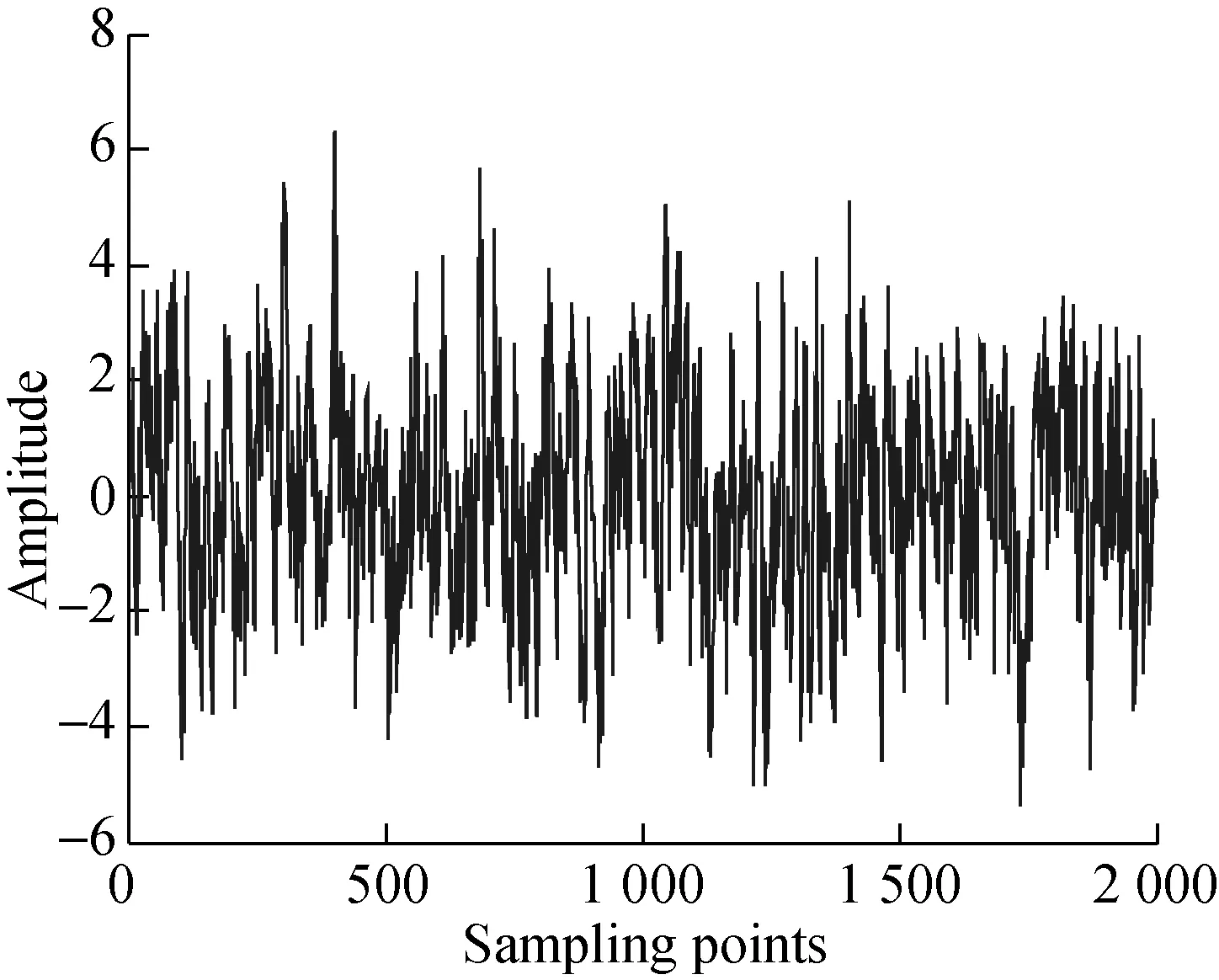
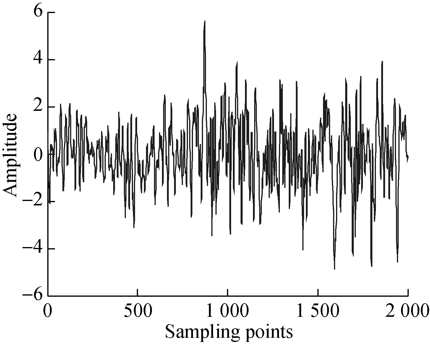
In Ref.[3], we established a signal generation environment as the front-end of a digital phased array radar system. Target echo, noise, clutter and jamming signals were analyzed theoretically and simulated. These signals were superposed linearly to structure the radar echo signals. Given that several kinds of clutter and jamming signals were presented, two optional combinations were chosen to generate multi-target radar echo signals. The first combination is the radar transmission signal, Gaussian white noise, Rayleigh distribution clutter and noise AM jamming; the second one is radar transmission signal, Gaussian white noise, K-distribution clutter and range false target jamming. Tab.1 lists the initial parameters of true and false moving targets, and this data was all captured by the actual radar equipment. Here the target lateral velocity is ignored, since the radar’s measurement performance will not be affected by this parameter. The target range will be transformed to a range gate, and the target velocity turned into a Doppler frequency shift[10]. Fig.1 shows the radar echo signals resulted from these two combinations.
Tab.1Initial parameters of true and false targets

TargetRange/kmRadial velocity/(m·s-1)True 115.00300True 220.00-100True 313.00-200False 113.50300False 215.45300
From Fig.1, it can be seen that since the target signals are totally overwhelmed by noise, clutter and jamming signals, they cannot be distinguished intuitively. These signals are considered to approximate the true radar returns, and can be employed to accomplish range and velocity measurements in a radar signal processing environment, as illustrated in Fig.2.
(a)
(b)

Fig.2 Radar signal processing environment
2 Pulse Compression
When using very short pulses, the radar range resolution can be improved greatly. However, this will lower the average transmission power, and prevent the radar from operating normally. Therefore, a suitable range resolution will be available when increasing the pulse width. The pulse compression technology can balance this trade off[11]. Pulse compression can not only improve the signal-noise ratio (SNR), but also acquires a higher range resolution. There are two methods to implement the pulse compression. They are the time domain method and frequency domain method.
2.1 Time domain method
In the time domain, the matched filter’s transfer function should be the LFM signal spectrum’s complex conjugate. Time-domain pulse compression is achieved by convolving the received signals(n) with the matched filter’s impulse responseh(n).h(n) is the conjugate mirror function ofs(n), and it is equivalent to acquiring the cross-correlation function of the received and transmitted signals’ complex conjugate in the time domain. The sampling number ofh(n) is consistent with the signal sampling numberN, and the matched filter outputy(n) is

(1)
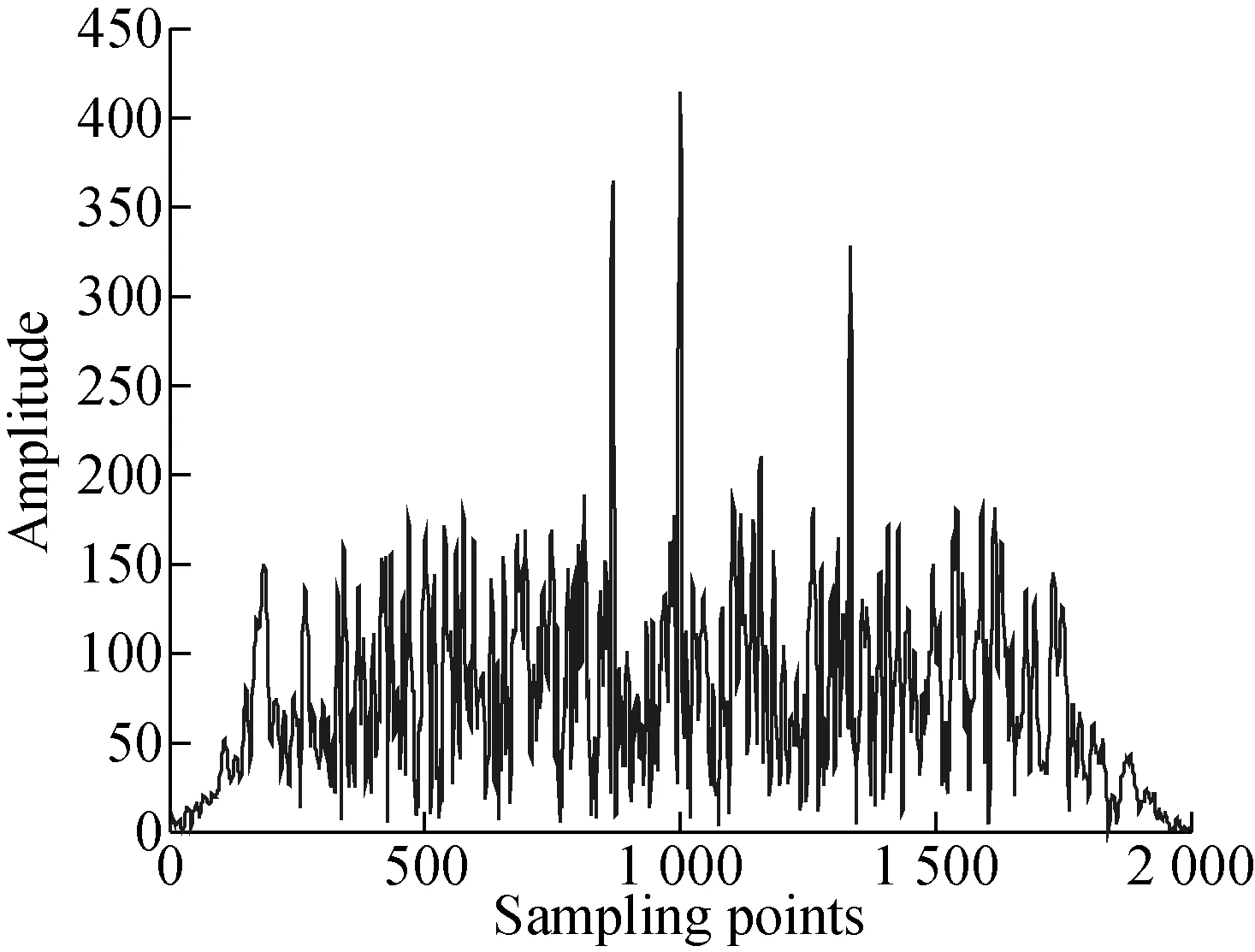
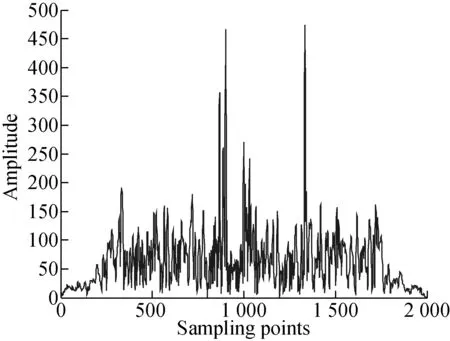
The structured filter is a non-recursive transversal filter[12], and the obtained compressed signals using the time domain method are shown in Fig.3.
(a)
(b)
2.2 Frequency domain method
The basic principle is as follows: The fast Fourier transform (FFT) is applied to the radar echo signal and the signal spectrumS(ω) is obtained;S(ω) is multiplied with its filter’s frequency response functionH(ω); the inverse fast Fourier transform (IFFT) is used to process again and output the compressed signal sequencey(n)[13-14]. The entire process of the frequency domain method can be expressed as
y(n)=IFFT[S(ω)·H(ω)]=
IFFT{FFT[s(n)]·FFT[h(n)]}
(2)
The pulse compression signals using the frequency domain method are shown in Fig.4. Compared with Fig.3, there is no significant difference between these two methods. However, when the compression ratio is small, the time domain method has good real-time performance and causes a short delay between the output and input data; whereas when the ratio is greater, the computational load can be reduced greatly by using the frequency domain method. Therefore, the frequency domain method is more desirable for processing the radar echo signal. The pulse compression results will serve as the input of MTI and MTD.
3 Moving Target Indication
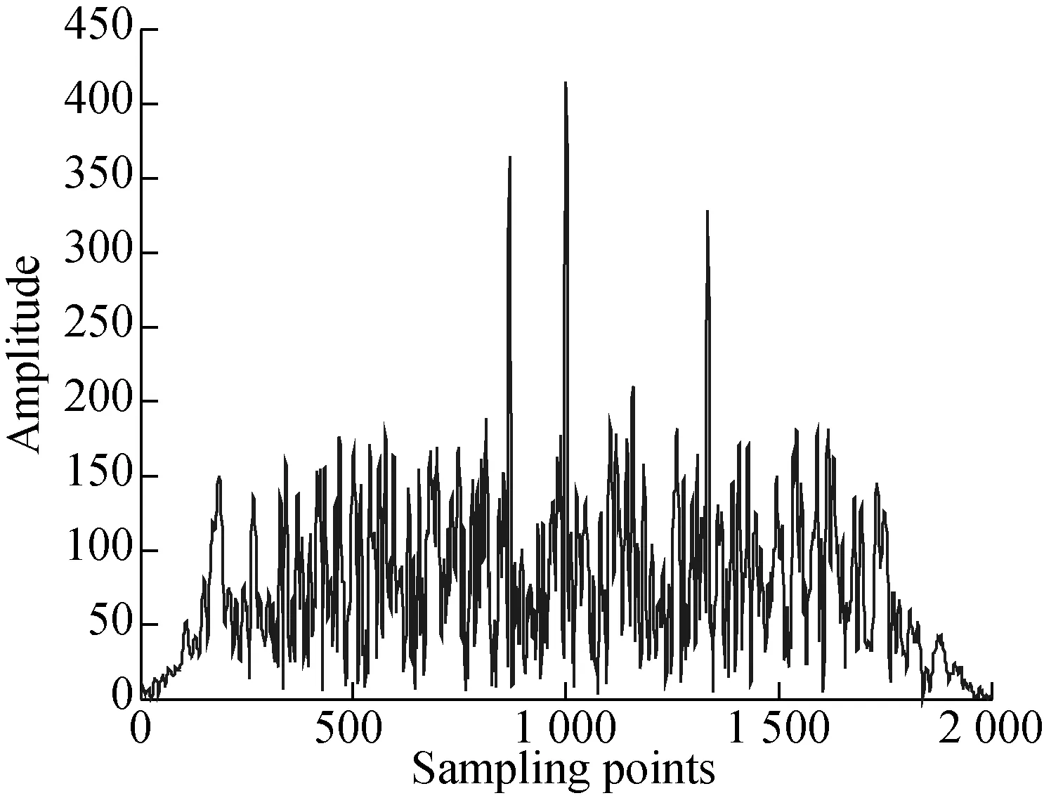
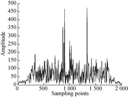
The MTI filter can suppress some target-like echoes produced by clutters and help moving target echoes pass the filter with no loss. However, the clutter spectrum generally centers at zero frequency and integral multiples of the radar pulse repetition frequency (PRF), and has a small-scale extension. In order to suppress the clutters, a filter should be designed with a very deep stopband locating at zero frequency and integral multiples of the radar PRF. The MTI filter can be devised through delay lines[15]. This filter’s frequency response should be periodic, with the zero value at integral multiples of the PRF. As a result, the targets whose Doppler frequencies are integral multiples of the PRF will experience very large attenuation. In this paper, the single and double delay cancellers are analyzed and simulated.
(a)
(b)
3.1 Single delay canceller
A single delay canceller is implemented by using a delayer to delay the echo signal one repetition period, and then subtracts the delayed signal from the original echo signal[16-17]. The single delay canceller is shown in Fig.5, and its difference equation is formulized as
y(n)=x(n)-x(n-1)
(3)

Fig.5 Single delay canceller
The single delay canceller is used to process the received pulse compression signals, and the simulation results are shown in Fig.6. It can be seen that, all the moving targets are captured. Although the low-velocity target signals are under restrictions, they can be displayed clearly. In addition, if the static targets were simulated, they would be eliminated, but they were not intended for simulation in this paper.
(a)
(b)
3.2 Double delay canceller
The MTI filter can be fulfilled through the double delay canceller, which is also called three-pulse canceller (see Fig.7)[18]. Its difference equation is
y(n)=x(n)-2x(n-1)+x(n-2)
(4)
Fig.8 shows the processing result of the double delay canceller. Compared with the single delay canceller, the

Fig.7 Double delay canceller
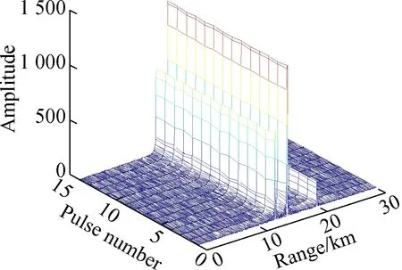
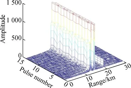
responses of low-velocity targets were restrained more severely, but they still can be identified, with the response amplitude of high-velocity targets obviously increasing. To measure multi-target range information from Fig.8, we utilize the Findpeaks function of Matlab to obtain the coordinate of every peak, and calculate the accurate range with the coordinate’s location value. The range measurement results from MTI are listed in Tab.2. By comparison with actual target ranges, the errors caused by Doppler frequency shift are small, which are in the order of 10-4to10-3. Also, the error magnitude is proportional to the moving velocity.
(a)
(b)

TargetTrue 1True 2True 3False 1False 2Range/km13.00515.01520.01013.51515.465
4 Moving Target Detection
MTD is a more effective frequency-domain filter technology, which is developed on the basis of MTI.Since MTI has a poor capability of suppressing fixed clutters and slowly moving clutters, a narrow-band Doppler filter bank should be connected after MTI processing. This filter bank covers the total repetition frequency range, and it can detect moving targets. In other words, it is equivalent to accumulating different channels coherently.
The coherent accumulation can be expressed as
(5)
whereTris the radar repetition period;Nis the accumulated pulse number; andwlis the weight coefficient.wlvaries regularly for every return as
wlk=exp(-j2πlk/N)l=0,1,…,N-1
(6)
wherelis thel-th coefficient output, and eachkrepresents a different weighting value corresponding to a different Doppler filter response[19]. Different from MTI, stationary targets and various clutters can be detected in MTD besides moving targets.
There are two implementation methods for narrow-band Doppler filter banks. One is adopting FIR filter banks in the time domain; the other is using DFT or FFT in the frequency domain. The latter method is much simpler when implementing the filter banks.Judge whether each filter has an output or not that can detect the Doppler frequency of moving targets, and then their velocity or fuzzy velocity can be worked out. Therefore, FFT filter banks are adopted in this paper to reduce the computation burden. Moreover, a new method is proposed to present the negative velocity for MTD, which means that a moving target is fleeing away from the radar.
4.1 Traditional method
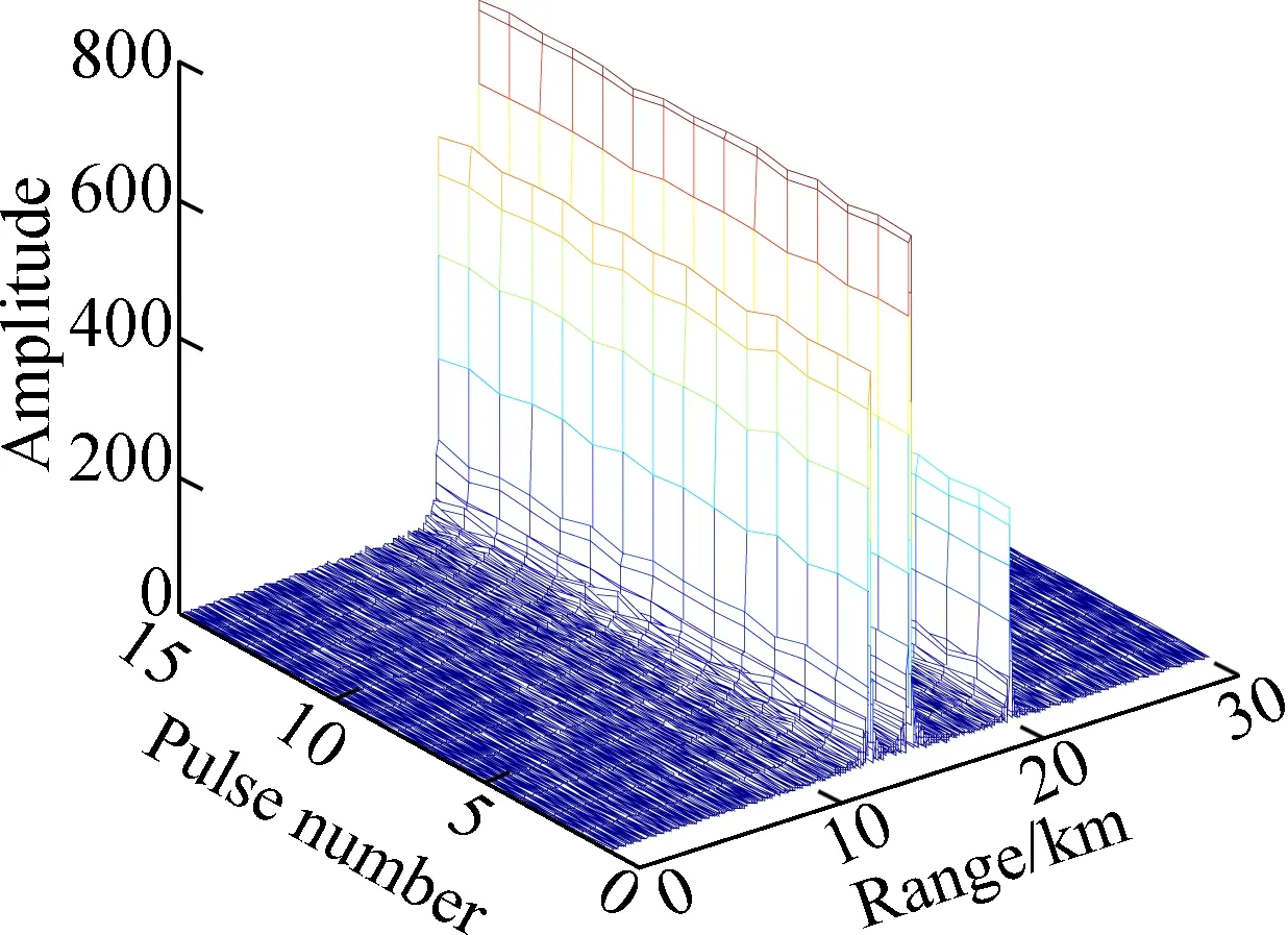
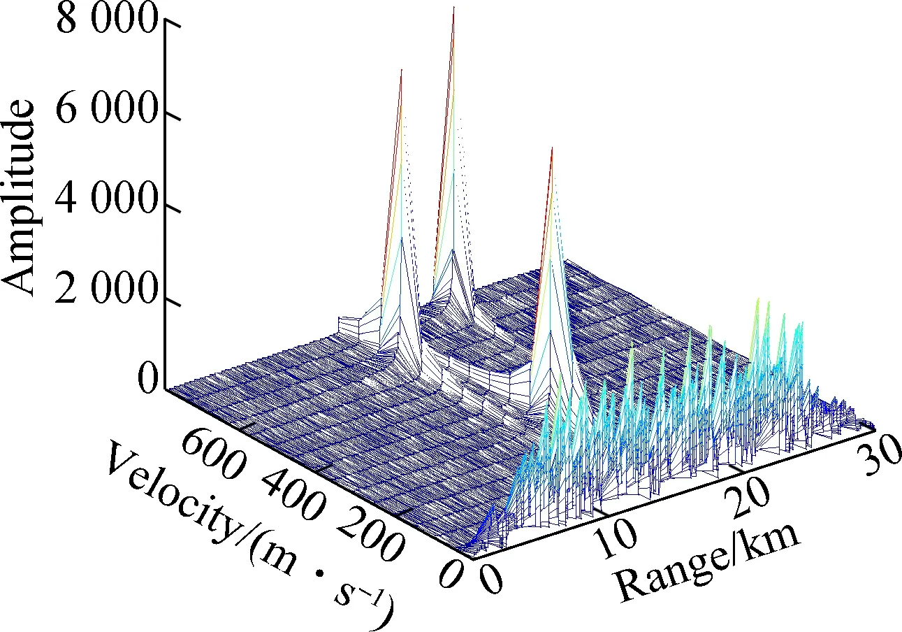
As suggested above, the traditional method applies FFT to all the pulse numbers of the compressed echo signal. Even the professional software SystemVue adopts this method for radar performance simulation[20-21]. The MTD results from the traditional method are shown in Fig.9. We can see that only the positive velocity is displayed correctly, and the negative velocity is turned into positive.
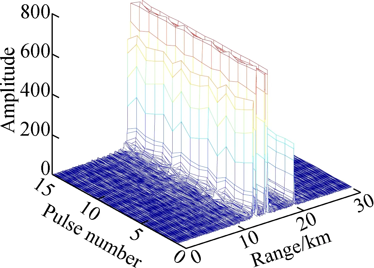
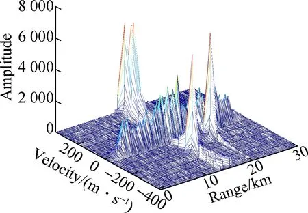
4.2 Proposed method
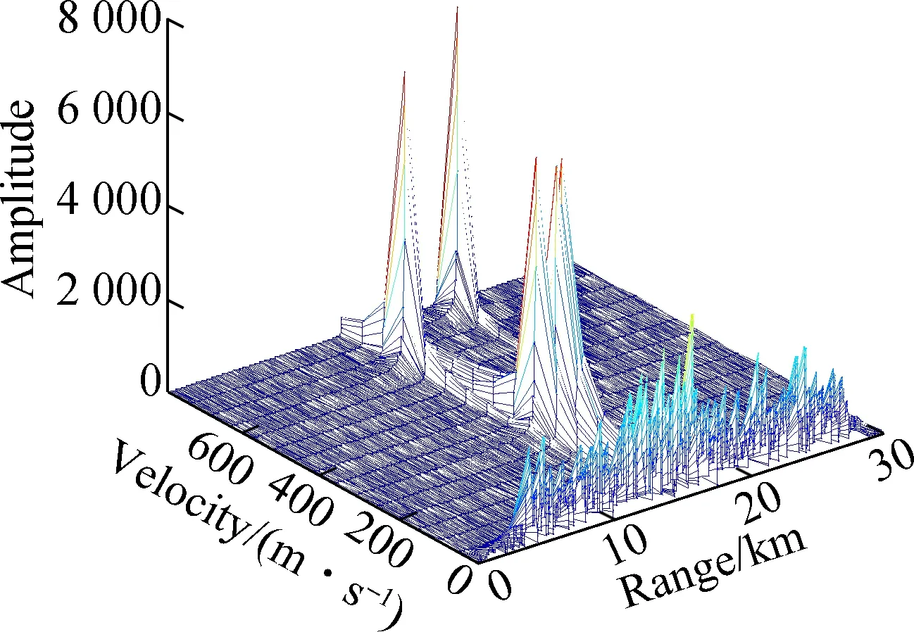
To represent the negative velocity correctly, a new method is proposed to divide the pulse number into two halves, and the FFT is applied to them, respectively. After FFT processing, the storage places of these two halves are exchanged and then assigned as the MTD results. Accordingly, they-axis range should be updated synchronously to show the negative values. As shown in Fig.10, all the target velocities are marked correctly, together with their range information. Here, the Findpeaks function will be used twice to measure multi-target range and velocity information from Fig.10. Since the MTD result is a 16×2 000 matrix, multi-target range values are firstly calculated through the Findpeaks function, and velocity values are secondly figured out in terms of the sequence number of range values.
(a)
(b)

(a)
(b)
The measure results from MTD are listed in Tab.3. It can be seen that the multi-target range values are the same as those in Tab.2, indicating that MTI has identical performance on measuring ranges with MTD. However,
Tab.3Range and velocity measurement results from MTD

TargetTrue 1True 2True 3False 1False 2Range/km13.00515.01520.01013.51515.465Velocity/(m·s-1)-208.333312.500-104.167312.500312.500
there is a constant error of 0.042 in comparison with each actual target velocity, and the reason is that using FFT inevitably causes spectrum leakage and a picket fence effect with truncation and discreteness in signal collection, resulting in obvious measure errors.
5 Conclusion
The multi-target range and velocity measurements of a phased array radar simulation system are investigated. As the input of the radar signal processing environment, the simulated radar echo signal is the linear combination of the target echo, noise, clutter and jamming signals. The time-domain and frequency-domain pulse compression methods are introduced to compress radar echo signals, and the frequency domain method is considered to be better at compression processing. Single and double delay cancellers are analyzed theoretically and simulated for MTI, and multi-target range is measured from the processing results of the double delay canceller. Due to the fact that the traditional FFT method only supports the positive velocity, a new method is proposed to present both the positive and negative velocity accurately for MTD. Also, the multi-target range and velocity can be measured from the MTD results. Simulation results indicate that, multi-target information can be extracted from the chaotic radar echo signals through pulse compression, MTI and MTD. Therefore, it is feasible to build the radar signal processing environment by using these processing technologies.
However, to detect target echo signals in a strong jamming environment, both certain SNR and constant false alarm rate (CFAR) processing are indispensable. In the future work, different CFAR methods will be studied and simulated to validate the true targets while keeping the false alarm rate constant. In addition, a graphical user interface of the digital phased array radar system will be designed. Except for the radar signal generation and processing environments, a radar data processing system also needs to be constructed, and the detected multi-target movements will be displayed on the radar search interface in real time.
杂志排行
Journal of Southeast University(English Edition)的其它文章
- Failure load prediction of adhesive joints under different stressstates over the service temperature range of automobiles
- Effect of fiber type on the bending and uniaxial tensile properties of high-strength high-ductility cementitious composites
- Effects of secondary water curing on the long-term strength and durability of concrete after steam-autoclave curing
- Variable structure control for descriptor Markovian jump systems subject to partially unknown transition probabilities
- Cooperative spectrum sensing algorithm based on bilateral threshold selection against Byzantine attack
- Joint resource allocation scheme based on evolutionary game for mobile edge computing
