Moving Personal-Cell Network: Characteristics and Performance Evaluation
2018-12-26SyedTariqShahMinsuShinYoungMinKwonJaeSheungShinAeSoonParkMinYoungChung
Syed Tariq Shah, Minsu Shin, Young Min Kwon, JaeSheung Shin, Ae-Soon Park, Min Young Chung,*
1 Department of Electrical and Computer Engineering, Sungkyunkwan University, Suwon, Republic of Korea
2 Mobile Access Research Division, Electronics and Telecommunications Research Institute, Republic of Korea
3 Department of Telecommunication Engineering, FICT, Balochistan University of Information Technology, Engineering and Management Sciences, Pakistan
Abstract: Recent years have witnessed a huge demand for ubiquitous communications services from continuously moving users. In order to provide seamless network services to high-mobility users, one of the promising solution proposed by 3GPP is the deployment of moving-relays. In this article, we introduce the concept of Moving-Personal-Cell (mPC),which is a type of moving-relays. mPC is a user-centric network, which aims to provide reliable network services to moving users. A mPC receives data-traffic from eNB and its neighboring mPCs via wireless backhaul and sidehual links respectively and forwards the received data to its serving users. In addition to this, mPC can also increase the network capacity by caching and distributing the popular contents to its serving users. Besides these pros, the mPC also has some limitations, as its performance is highly affected by cross-tier and co-tier interferences. In this article, we analyze the effect of these interferences on mPCs performance. Our results show that the performance of mPC network is equally affected by the capacity of wireless backhaul,sidehaul, and access links. Moreover, since mPCs accommodate data traffic from wireless backhaul, sidehaul links, and content cache,their performance is also affected by the ratio of data-traffic delivered via these links.
Keywords: heterogeneous networks; moving small cells; fixed small cells; moving cache;network performance evaluation; next generation networks
I. INTRODUCTION
The number of smart mobile devices and their demand for mobile data traffic is growing exponentially. It is expected that there will be more than 5.2 billion (static and moving)smart device users in 2019 [1], and a significant number of these users will be individually moving users or vehicular users (i.e., users traveling at a high-speed public transportation vehicle like trains, buses, and subways). To accommodate this enormous amount of data traffic, Mobile Network Operators (MNOs)are already using advanced communication techniques, for instance, Carrier Aggregation(CA) and Multiple Input and Multiple Output(MIMO). In addition to these state of the art communication techniques, MNOs have also adopted smart network architectures known as heterogeneous networks (HetNets) [2][3].As shown in figure 1, existing HetNet consists of various types of Fixed Small Cells (fSCs)such as femto-cells and pico-cells. These fSCs are deployed under the umbrella of macro-cell
where they share the traffic load of macro-cell by providing reliable network services to static users in densely populated areas [4][5][6]. Moreover, in HetNets, fSCs reuse the radio spectrum assigned to macro-cell,therefore they can also significantly increase the network capacity [7]. Besides all these advantages, fSCs in HetNets also have several limitations. Since fSCs are fixed, they require complex and cost inefficient wired backhaul infrastructure to connect them to the central network. Furthermore, due to their static nature, they cannot provide reliable network services to moving users.
In this article, we introduce the concept of Moving-Personal-Cell(mPC), which is a type of moving-relays.mPC is a user-centric network, which aims to provide reliable network services to moving users.
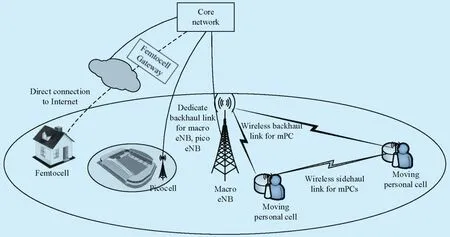
Fig. 1. An example of next generation HetNets with mPCs.
As mentioned earlier that the number of moving users are dramatically increasing.This rapid increase of high-mobility users and their data hungry applications have urged the industry and research society to come up with more innovative and cost efficient network solutions [8][9]. To increase network capacity and provide seamless network services to these moving users, one of the promising solution proposed by Third Generation Partnership Project (3GPP) is the deployment of moving relays [10][11]. In this article, we introduce moving personal-cell (mPC), which is a type of moving relays. As shown in figure 1, mPCs are user-centric networks which receive data traffic from both evolved Node B (eNB) and their neighboring mPCs via wireless backhaul and sidehaul links. The received information is then forwarded to their respective users. In addition, to receive and forward data traffic,mPCs can also store the popular media contents in their cache. Later, the stored information can be dissipated among requesting users. This content caching mechanism can not only increase the network capacity but it can also reduce the backhaul traffic load. Note that the cache in our considered system model is assumed to be a proactive cache. Which means that the cache of mPCs in our proposed scheme is only updated in low traffic hours(such as at night) when the traffic load on the backhaul link is very low. Furthermore, no specific content selection scheme is considered, because the aim of this work is to analyze the impact of mPC with cache on overall system performance under the constraint of limited wireless backhaul/sidehaul capacity.It is obvious that, compared to existing fSCs,mPCs are more dynamic and flexible in nature because of their wireless backhaul and sidehaul links and therefore, they can play a vital role in future HetNets by providing seamless networks services to high-mobility users.
1.2 Contributions
A preliminary conference version of this paper has been published in [12]. In [12] we have mainly focused on the simulator design and construction. In this article, we evaluate the performance of mPCs networks using our system-level event-driven based simulator [12].System-level simulation is considered as one of the most efficient methodologies to analyze the performance of various network scenarios[13]. In our proposed network, mPC operates in three different modes i.e., full cache mode,a relay mode, and hybrid mode. In order to thoroughly investigate the performance of mPCs in future HetNets, we have considered three different network architectures namely,macro-cell only, macro-cell and fSCs, and macro-cell and mPCs. Furthermore, we have also explained the different modules, their configurations, and working of our system-level simulator. In performance evaluation, we have analyzed the cross-tier interference between Macro Base Station (MBS) and mPC and co-tier interference among neighboring mPCs. The effects of these interferences on overall network capacity are also thoroughly discussed. We also show that the use of cache in mPC can reduce the traffic load of a wireless backhaul link between MBS and mPCs.
The rest of the paper is organized as follows: section II provides the related works.The preliminaries and different operating modes of mPC network are explained in section III. Section IV contains the detailed discussion of our proposed network architecture.Functionalities and components of our developed simulator are introduced in section V.Section VI contains the performance evaluation of mPC network and section VII provides the conclusion of this paper.
II. RELATED WORKS
The network densification due to growing number of users in urban areas has urged the MNOs to deploy more fSCs in their existing HetNets. The existing HetNets consists of various low power fSCs such as such as femto-cells, pico-cells, and remote radio heads.These low power nodes are deployed underlying MBSs and since they reuse the radio spectrum assigned to MBS, they are identified as a potential solution to improve the overall network coverage and capacity [14][15][16]. Due to these features, the deployment of HetNets in next generation networks has been rigorously studied in the literature[13][15]. Besides these advantages, fSCs in existing HetNets have some limitations. One of the major limitation is its mobility. Since fSCs are fixed they cannot provide reliable and seamless network services to moving users, 3GPP has proposed the deployment of mPCs [10].
The idea to deploy mPCs and improve the network service experience of high-mobility users has been studied in [10][17]-[22]. In[17], Phan et al. have first introduced the concept coordinated and cooperative relay system(CCRS) for densely populated high-speed vehicular users in LTE networks. They show that the use of CCRS can not only improve the network experience for vehicular users but also reduces the additional network complexity such as handover and authentication.
Sui et al. in [18]-[21] have studied the performance of Moving Relay Nodes (MRNs)in LTE based HetNets. MRNs are the type of mPCs which are deployed on the rooftop of a high-speed vehicle. Similar to mPCs, MRNs also aim to provide seamless network services to vehicular users. In [18] the authors have compared the performance of MRNs with direct MBS and Fixed Relay Nodes (FRNs).Their results show that compared to MBS and FRNs, the deployments of MRNs can significantly improve the quality-of-service (QoS) of vehicular users. A similar study is conducted in [19] where it is shown that at high vehicular penetration loss (VPL) the MRNs outperforms the conventional MBS and optimally deployed FRNs. Energy efficiency of MRNs has been studied in [20] and it is concluded that the use of MRNs can considerably reduce the overall transmit energy compared to the conventional MBS case. The impact of handover between MBS and relay nodes (i.e., MRNs and FRNs)on vehicular user has been studied in [21]. The power outage probability of vehicular users is calculated and it is shown that for moderate to high VPLs the MRN outperforms the direct MBS and FRN cases. To mitigate the cross-tier interference between MBS and MRNs in an ultra-dense urban scenario is studied in [23].The performance of various legacy interference coordination mechanisms such as almost blank subframes (ABSs) [24] ([25]Ch. 31],Multi-antenna solutions ([26]Ch. 20), interference rejection combining (IRC) [27], and inter-cell interference coordination (ICIC) [28]are evaluated for an MRN based ultra-dense HetNet. They conclude that in a dense urban scenario the IRC scheme is most suitable.
In [29], the authors have proposed a resource allocation and power control scheme for mPCs network. In their considered single cell model, the mPCs are assumed to be deployed in a train whose mobility pattern is deterministic. Two different resource allocation algorithms based on interference-free resource block (RB) and interference-percentage RB are proposed. Furthermore, in order to maximize the QoS of the network, an iterative RB and power allocation algorithm is also proposed.They concluded that the interference-free RB based resource allocation can achieve better throughput than interference-percentage RB allocation scheme. A backhaul resource allocation problem for the newly arrived mPCs in the network has been studied in [30]. In their considered network, orthogonal backhaul and access link resources are considered for both macro-cell and mPCs. The proposed resource allocation algorithm aims to maximize the backhaul data rates of newly arrived mPCs while maintaining the QoS of the existing macro-cell users and mPCs. With the help of numerical results, the superior performance of the proposed algorithm is demonstrated. The concept of traffic hotspot offloading to mPCs has been studied in [31]. A Manhattan city based mobility model is considered and it is assumed that both macro-cell users and mPCs share the same radio resources. It has been shown that the efficiency of mPCs in the network significantly increases when the mPCs are moving near the traffic hotspot.
In high mobility scenario where vehicles are moving at a very high speed, the rapid variations of mobile channels combined with feedback delays can yield to an outdated channel state information (CSI) at MBSs.However, this problem can be solved by using a predictor antenna [32]. A predictor antenna is placed some distance ahead of the transmission antenna. Since the vehicle direction and velocity is nearly constant during each CSI reporting period, the channel state estimated by the predictor antenna can be used as a channel state which the transmission antenna will experience a while later when it moves forward to that position. More details on predictor antenna can be found in [32].
Nevertheless, most of these studies either highlight the various potentials of mPCs or investigate different interference mitigation schemes. Moreover, to the best of our knowledge, unlike our work, none of these previous studies have investigated the mPCs with caching and sidehaul communication capabilities.
III. MOVING PERSONAL-CELL NETWORK
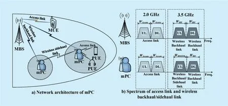
Fig. 2. Architecture of moving personal-cell network.
The mPC network consists of four network entities, MBS, macro-cell UE (MUE), mPC,and personal-cell UE (PUE) as shown in figure 2. The mPC network supports three kinds of wireless links: access link, wireless backhaul link, and wireless sidehaul link. The communication link between MBS (or mPC)and MUE (or PUE) is known as an access link. For access link, MBSs and mPCs share the same radio resources of 2 GHz frequency band. Wireless backhaul and sidehaul links are connections between an MBS and mPCs,and between mPCs, respectively. In order to provide higher link capacity than access link,Wireless backhaul and sidehaul links use radio resources of 3.5 GHz frequency band[33]. Wireless backhaul link can use the full duplex mode based on FDD, while wireless sidehaul link uses the half duplex mode. In order to avoid severe interference from MBS,mPCs reuses the uplink resource of wireless backhaul for its sidehaul link communication.Another interesting idea is to use the WiFi technology in mPC access link. However,in practical it is very challenging because,in order to provide the user authentication,charging, and security features, the existing WiFi modules in UEs have to access the UEs universal subscriber identity module (USIM)which requires significant hardware and software upgrade of existing WiFi modules [34].Furthermore, unlike cellular operators, the WiFi networks operate on the free industrial,scientific and medical radio (ISM) bands, and interference coordination in these radio bands is very difficult. Therefore, it is difficult for the cellular operators to guarantee QoS while using WiFi technology.
Moreover, it is also worth mentioning that the aim of our proposed scheme is to evaluate the performance of a fully loaded mPC network with active sidehaul links and cache, under the constraint of limited wireless backhaul capacity. Therefore, in our proposed network model, we have considered that the number of mPCs in each macro cell and the number of PUEs in each mPC are uniform and fixed. The aim of such network model is to find the upper bound of network capacity. Consequently, due to these considerations, the traffic conditions of an mPC in our proposed network does not vary over time and the resource allocation is static.
In this paper, we have used Shannon capacity formula to estimate the different throughputs and link capacities. The use of the Shannon capacity formula is motivated by the fact that it offers a simplified way to accurately evaluate the capacities of links with different bandwidths. Furthermore, the downlink performance of mPC network in our considered system model varies according to the operating mode of mPCs. In this paper we mPC has three operating modes: full cache mode, a relay mode, and hybrid mode. The notations used in this section are summarized in Table 1.
3.1 Full cache mode
In the full cache mode, mPCs only transfer the stored data from their cache to their respective PUEs via access link. Thus, downlink performance of mPC network is determined by downlink capacity of access link (CA,m) which is total throughput of PUEs served by , and it can be calculated as

where and indicates the available bandwidth of access link and number of UEs attached to mPC m, respectively. The SINR of PUE j(SINRPUE,j) can be calculated as
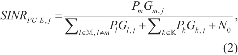
where l represents the interfering mPCs. The three factors in the denominator of (2) represent the interference caused by the neighboring mPCs, MBSs and AWGN noise, respectively.We assume that an MBS (or mPC) uniformly allocates radio resources to its serving MUEs(or PUEs). When M number of mPCs are deployed in a macro-cell, the downlink capacity of mPC network can be estimated as

Table 1. Definition of notations.

3.2 Relay mode
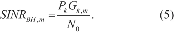
The mPCs operating in relay mode receive data traffic from MBS via wireless backhaul link and forward it via access link. In relay mode, the performance of mPC network is affected by two factors, the downlink capacity of wireless backhaul link and access link. Existing studies on HetNet assume that wired backhaul links for fSCs have perfect and reliable condition with infinite capacity [35][36]. Thus,network performance is mainly determined by the capacity of access link. However, in mPC network the backhaul link is wireless and has a limited capacity. Thus the performance of mPC network is affected by both capacity of wireless backhaul link and access link [37].To estimate the capacity of wireless backhaul link, we assume that an MBS uniformly allocates backhaul radio resources to mPCs that are located in its coverage area. Under these assumption, capacity of wireless backhaul(CBH,m) is defined as

Where M is the total number of mPCs in the network. The backhaul link SINR of mPC m(SINRBH,m) can be calculated as
Consequently, when mPCs operating in relay mode, capacity of mPC network is determined by minimum capacity of wireless backhaul link and access link as
3.3 Hybrid mode
In hybrid mode, mPCs receive data traffic via sidehaul and backhaul links and forward it to their attached PUEs. In this paper, we assume that a wireless sidehaul link is established between two mPCs whose geometric distance is less than constraint distance (dConst). Here the constraint distance is defined as the maximum allowed distance between two mPCs to establish a sidehaul link. In case when the distance between two mPCs is greater than , capacity of wireless sidehaul link is determined by the SINR and sidehaul bandwidth (WSH) of receiving mPC. To enhance the spectral efficiency,mPCs reuse all available radio resources for wireless sidehaul link. By considering the above assumptions, the capacity of wireless sidehaul link is estimated as
where is ratio of data traffic transferred between mPCs.
In hybrid mode, mPCs can send cached data to their respective PUEs. When an mPC recognizes that a certain data such as a music or video file is repeatedly requested by its PUEs, the mPC can store that particular data file in its cache. If some other PUE of the same mPC requests the same data, the mPC sends the stored data to its PUEs, hence reduces the traffic load of the wireless backhaul link. Thus, the capacity of cache transmission(Ccache,m) is same as the ratio of duplicated data in overall wireless backhaul capacity, which is estimated as

where is the ratio of duplicated data.
Downlink capacity of mPC is the minimum capacity among total traffic and the access link. In addition, total traffic capacity of wireless backhaul link and caching transmission should be lower than capacity of access link except that of wireless sidehaul link. Thus,capacity of mPC network in hybrid mode is estimated as
It is obvious that the total capacity of a cell is the sum of both capacities of macro-cell and mPC network, which is estimated as

where capacity of macro-cell (Cmacro−cell) is the total throughput of N number of MUEs served by an MBS, which is evaluated as

Since, both mPCs and MBS are reusing the same radio resources in their access links, the SINR at MUE n (SINRn) can be calculated as

IV. NETWORK ARCHITECTURE
In order to analyze the performance of mPCs in different HetNet environments, we have considered three different possible HetNet scenarios: macro-cell-only, macro-cell and fSCs,and macro-cell and mPCs. This section of the paper provides details on network architecture of each scenario.
4.1 Macro-cell-only
In macro-cell-only scenario (Case-1) a conventional cellular network is considered where only MBS is responsible for providing network services to all UEs in its coverage zone(cell). figure 3 a) shows the cell architecture of case-1. In this article, total 19 cells are considered. One MBS located in the center of the cell with three hexagonal sectors is considered according to 3GPP simulation specifications[33]. The inter-site distance is 500m and a total of 60 UEs are randomly deployed and moved in each cell. To capture the real-life mobility pattern of mPCs and UEs a random walk mobility model is adopted [38]. According to our considered random walk model the node travels in a random direction with random velocity and flight time. Both intra and inter-cell interferences are considered,however, no interference management scheme[39] (i.e. ICIC or Fractional Frequency Reuse(FFR)) is used to mitigate these interferences.
4.2 Macro-cell and fSCs
To evaluate the performance of mPCs in an environment closer to realistic HetNets, a 2-tier network (Case-2) consisting of a macro-tier and small-cell-tier (fSCs) is considered.The macro-cells are deployed in a similar manner as explained in case-1. Based on the deployment conditions of the fSCs, the case-2 scenario is further classified into two cases (Case 2-1 and Case 2-2). The Case 2-1(Fig.3b) represents the scenario where the fixed small cells are deployed in form clusters.Such a network environment can usually be found in places where a large number of users reside in a short space such as multistory office buildings, shopping malls, student dormitories, etc. Total 4 non-overlapping clusters each with radii of 50m are randomly deployed and the number of fSCs in each cluster varies from 1 to 5. The distance between the center of a cluster and MBS is always more than 105 m, while the distance between the centers of any two clusters is always more than 100 m.On the other hand, in case 2-2 (Fig.3 c), varying numbers (4 to 20) of fSCs are randomly and sparsely deployed in each macro-cell. In both cases (2-1 and 2-2), total 40 fSC UEs(SUEs) and 20 MUEs are randomly deployed with uniform distribution in each cell. MUEs can freely move around in overall macro-cell while SUEs are only allowed to move within the coverage zone of their serving fSCs.
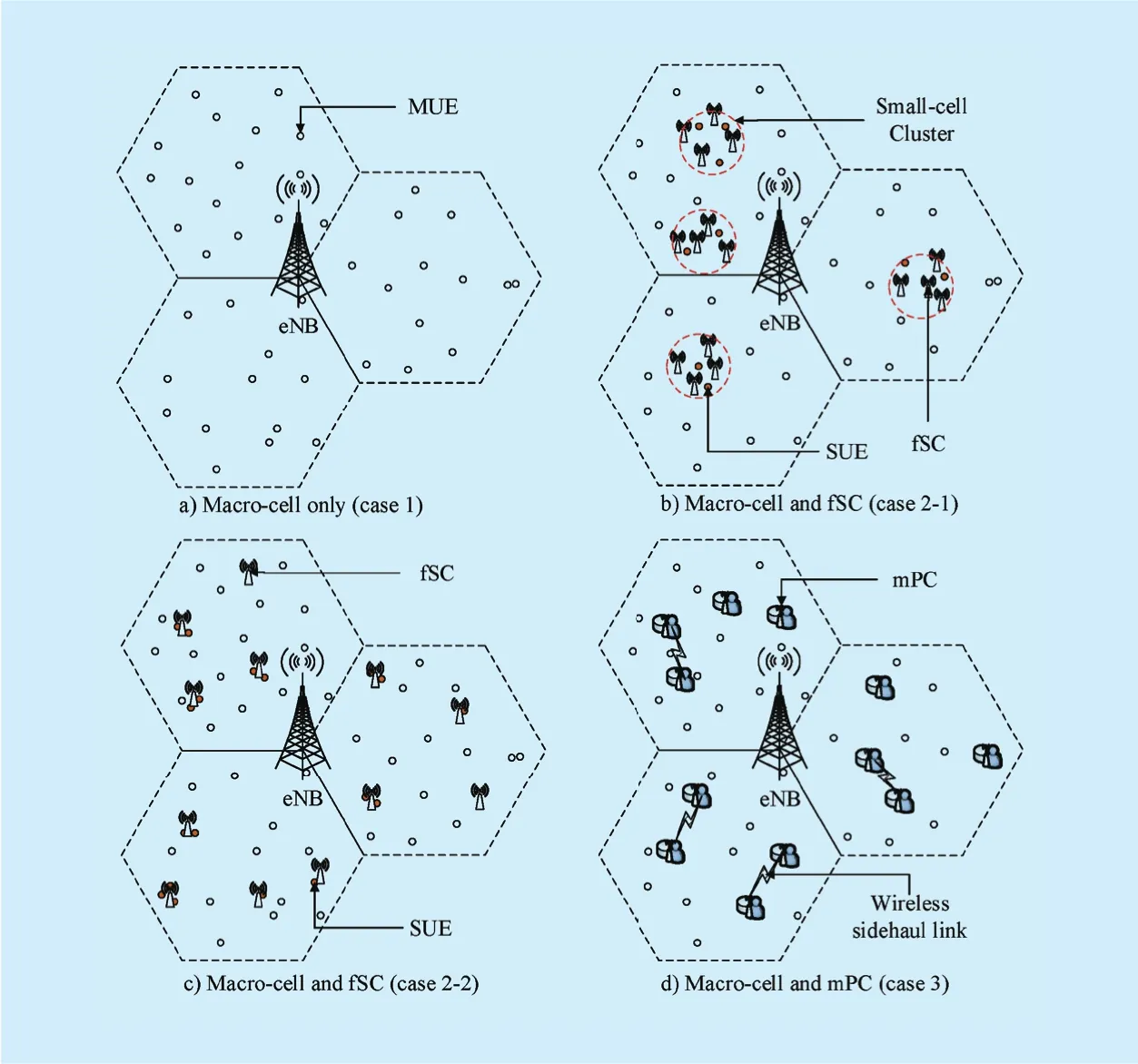
Fig. 3. Network Architecture of considered HetNet scenarios.
4.3 Macro-cell and mPCs
In macro and personal cell scenario (case-3),a 2-tier network consisting of a macro-tier and moving personal-cell-tier (mPCs) is considered. The macro-cells are deployed in a similar manner as explained in case-1 while varying number of mPCs (4 to 20) are uniformly distributed in each macro-cell. Total 40 PUEs and 20 MUEs are uniformly distributed in each cell and PUEs are always located within the coverage of their serving mPCs. A random walk mobility model is adopted for mPCs,moreover, PUEs are restricted to always move along with their serving mPCs. figure 3 d)shows the detailed network architecture of case-3.
Table 2 provides the summary of the considered HetNet scenarios. More details about network and simulation parameters are provided in section V and VI.
V. SIMULATOR DESIGN AND DEVELOPMENT
In the designed system-level simulator for mPC network, we focus to emulate the radio environment and mobility of UEs as defined in [40][41]. To evaluate the performance of aforementioned four HetNet scenarios in realistic environment, we have modeled the channel conditions by considering various multi-path and shadow fading. In addition,the mobility of both UEs and mPCs are also considered. Our designed simulator consists of two main parts: 1) cell layout configuration part, and 2) functional part.

Table II. HetNet scenarios.
5.1 Layout configuration
Cell layout configuration part provides initial base stations deployment and distribution of UEs in a macro-cell, fSC, and mPC according to the user defined scenarios. Beside the above mentioned three scenarios, user can define any other possible scenario by using the layout configuration part of our simulator.
5.2 Functional part
The functional part of simulator includes numerous functions and models that are used for emulating LTE-Advanced system-based HetNet environments. This part comprises of three modules; channel modeling, mobility management, and event processing. Channel modeling module of our simulator considers the path loss, multi-path fading, and shadow fading to estimate the attenuation in received signal power transmitted by MBSs, fSCs,mPCs and UEs. To estimate path loss in macro-cell and small-cell, we adopt ITU UMa and UMi models defined in [40] and [42], respectively,
where d, W, fcand h depict the distance between the transmitter to the receiver, street width, carrier frequency, and average building height, respectively. Furthermore, hBSand hUTrepresent the antenna height of base station and UE, respectively. For MBS equipped with three sector antennas, we consider that the gain of sectorial antenna is based on angle between transmitter and receiver and can be estimated as

where ϕ3dB=70 is angle in degrees when the signal strength is half of its peak value and its value is set according to [40][42]. Amis the maximum achievable gain and its value is set to Am=25d B and ϕ is the angle between user position and antenna’s main lobe. We also consider multipath fading with mean value 1 of exponential distribution, and shadowing with a normal distribution of zero mean and standard deviation six [40].
To simulate realistic environments, user mobility is very important because the movement of UEs changes the topology of the wireless network, which effects its overall capacity. In the mobility management module of our simulator, we have included the random walk models for the mobility of UE and mPCs. According to the random walk model of [41], first, a UE randomly selects its destination, velocity, direction and flight time then it determines the coordinates of selected destination and starts moving towards it. This procedure is repeated whenever a UE reaches its destination. Mobility management module is also responsible for reporting channel quality indication (CQI) of moving UEs to their corresponding BSs. There are two types of CQI reports defined by 3GPP LTE according to their reporting interval, i.e., periodic and aperiodic. Type of information contained in the report also classifies the reports into wideband and sub-band CQI reports. The wideband CQI report includes a measurement referring to the entire system bandwidth, while the later type contains measurements of various sub-bands.
The framework of the simulator is built upon event-driven programming [43]. In event-driven programming, the flow of the program is determined by different events.Event-driven programming can reduce unnecessary loops and operations and can enhance efficiency and performance of the program that is why it is widely used in well-known network simulators such as OPNET, QualNet,and NS-2. The main loop of the program in our simulator is event processing module,Ff which is divided into two sections, i.e., event selection and event handling. Moreover, to arrange the generated events, linked-list data structure based event queue is defined. In event selection, event located on the top of the queue is loaded and based on the type of the event, the appropriate event handler is executed. As a result, the event handler processes the event using global variables, functional modules, and information contained in each event.
VI. PERFORMANCE EVALUATION
In order to evaluate the downlink performance of our considered mPC network, we have developed a C++ based system level simulator. All the calculations in our simulator are performed according to the equations and network scenarios presented in Section III. More detailed simulation parameters for each scenario are provided in Table 3 [40][42]. In all scenarios, the number of macro-cells (i.e., site)is 19. MBSs are deployed in the center of all the macro-cells and the inter-cell distance is 500 meters. In the performance evaluation, we consider that fSCs and mPCs operate in open mode so that they can significantly observe the effect of cross-tier interference between different heterogeneous cells. The value of α and β are set to 0.3 and 0.4, respectively.
With the help of our developed simulator,we measured the access link capacity of all considered scenarios. figure 4 shows the total cell capacity with a varying number of fSCs(or mPCs) per macro-cell, when all mPCs operate in full cache mode. In Case 1, MBS uniformly assigns the radio resources of l0 MHz to its serving UEs and all UEs receive data from their respective MBS in downlink access link. The total cell capacity of Case-1 is nearly 26 Mbps. The spectral efficiency of access link increases in HetNet scenarios (Case 2-1 to 2-2, Case 3) because all fSCs (or mPCs)reuses the same frequency band of macro-cell.Thus, total cell capacity increases under Het-Net scenarios. In Case 2-1 to 2-2, the deployment strategy of fSCs also affects the total cell capacity. When fSCs are densely deployed in the form of clusters (i.e., Case 2-1), MUEs and SUEs located in clusters suffer from severe inter-fSC interference. However, under uniform deployment scenarios (i.e., Case 2-2),interference of fSCs is relatively reduced,because the fSCs are sparsely deployed in macro-cell. Thus, Case 2-2 has higher total cell capacity compared to Case 2-1, although the number of fCSs per macro-cell is same in both cases. Meanwhile, the total cell capacity is highest in Case 3. It is because mPCs uses low transmit power and as a result causes less interference to neighboring mPCs. On the other hand, fSCs are using higher transmit power(because of their larger footprint) compared to mPCs and thus induce more interference in the network. Unlike Case 3, the rise in total cell capacity impedes in Case (2-1, 2-2) when the number of fSCs increases from more than 12.It is worth mentioning that the same number of fSCs and mPCs are deployed in each macro cell.

Table III. Simulation parameters.
Fig. 4. Total cell capacity (all mPCs operate in full cache mode).
Figure 5 shows the total cell capacity when all mPCs operate in relay mode, where mPCs receive data traffic from MBS via wireless backhaul link. mPCs then forward the data to their serving PUEs via access link. If mPCs operate in relay mode, total capacity is determined by the minimum capacity of access link and wireless backhaul link. When the bandwidth for wireless backhaul link is the same as that of access link, bottleneck is wireless backhaul link. Thus, total capacity does not increase linearly in relation to the increasing number of mPCs per macro-cell. In addition,figure 5 also shows that the total capacity of case 3 does not depend only on the bandwidth of wireless backhaul. It is shown that, if we increase only the bandwidth of wireless backhaul link from 10 MHz to 100 MHz, the total capacity only increases from about 50 Mbps to 200Mbps. It implies that access link becomes bottleneck when the bandwidth of backhaul link is larger than that of access link.
To further analyze the bottleneck issue in more detail we have simulated the HetNet with varying backhaul, sidehaul and access link bandwidths. It has been shown in figure 6 that both backhaul/sidehaul and access link bandwidths have similar effects on the network performance. In other words, when only the backhaul/sidehaul link capacity is doubled,the overall network throughput and the total personal cell throughput do not increase with the same ratio. It is because of the interference in the access link and, in this case, the access link act as a bottleneck of the HetNet. Similarly, increasing the access link capacity only does not increase the overall network throughput and the total personal cell throughput with the same ratio. In such a case the wireless backhaul/sidehaul link acts as a bottleneck of the HetNet. However, in real time network scenarios it is impractical to increase the bandwidths of backhaul, sidehaul and access links beyond a certain limit [40]. Thus, introducing mPCs with the ability of caching and sidehaul communication can considerably increase the overall network capacity and performance.In other words, keeping in view the spectrum availability constraint, deploying mPCs with hybrid mode enabled can highly improve the overall network performance.
Figure 7 shows total cell capacity according to the number of mPCs operating in hybrid mode. In hybrid mode, mPCs can receive data traffic from an MBS via wireless backhaul and sidehaul link, and forward it to its serving PUEs. In addition, mPCs can also transmit the cached data to its serving PUEs. If the bandwidth of wireless backhaul and sidehaul link is 10MHz, a total cell capacity of mPC network with four mPCs increases about 3.8 times as compared to Case 1. In addition, if more mPCs are deployed in macro-cell, total cell capacity also increases because the capacity of wireless side-haul link increases linearly with the increasing number of mPCs. However, in full cache mode (Fig. 6) the capacity of access link in mPC network is higher than that of fSC network. On contrary, the total cell capacity of mPCs operating in hybrid mode is lower than that of fSC network due to the limited capac-ity of the wireless backhaul link. When the bandwidth of wireless backhaul and sidehaul link increases from 10MHz to 100MHz, a total cell capacity of mPC network increase about 3 times.

Fig. 5. Total cell capacity (all mPCs operate in relay mode).
Fig. 6. Cell capacities with varying backhaul, sidehaul and access link bandwidths.
Fig. 7. Total cell capacity (all mPCs operate in hybrid mode).

Fig. 8. SINR CDF of macro UEs for case 1, 2-1, and 2-2.
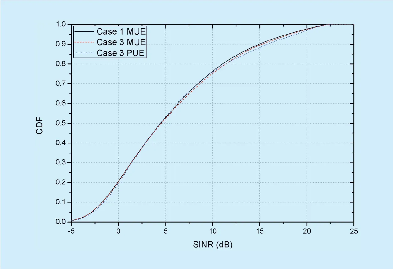
Fig. 9. CDF of MUEs SINR in the presence of mPCs (case 3).
The impact of interference from clustered(case 2-1) and uniformly (Case 2-1) deployed fSCs on MUEs is depicted in figure 8. Since both fSCs and macro cell are using same radio resources in their access links, it can be observed that the MUE SINR is reasonably affected by the interference from fSCs. More specifically, the clustered deployment of fSCs (Case 2-1) have a more severe impact than uniform deployment (Case 2-2). It is because in case 2-2, the MUEs located near fSCs receive interference from fewer fSCs compared to case 2-1. On the other hand, as shown in figure 9, the SINR of MUEs in case 3 is not significantly affected by the mPCs. It is because unlike fSCs, the mPCs operate at a relatively lower transmit power and also their coverage footprint is smaller than fSCs. Furthermore, it can also be observed from figure 9 that despite mobility, the SINR performance of PUEs is very close to MUEs.
VII. CONCLUSION
In terms of overall system capacity, MNOs can significantly benefit by deploying mPCs.However, the effects of mPC deployments in the network should be carefully analyzed before their release, in order to minimize the risks and shortcomings of mPC in real markets. Thus, we developed a system-level simulator that can simulate different scenarios for LTE systems considering real time HetNet environments. In our developed simulator, we have described three functional parts, wireless channel modeling, mobility management, and event processing modules, to emulate real time LTE systems and network environments.From our results, we conclude that various characteristics of mPC may affect the overall performance of HetNets, and different aspects should be considered in the co-channel deployments.
For future studies, we are aiming at incorporating the power control schemes in our simulator, which will effectively reduce crossand co-tier interference in mPC networks.In addition, various resource partitioning schemes can be addressed, which can statically or dynamically divide radio resources for macro-cell and mPC, in order to mitigate interference and improve overall system performance.
ACKNOWLEDGMENT
This work was supported by Institute for In-formation and communications Technology Promotion (IITP) grant funded by the Korea government (MSIP) (No.R0101-15-244,Development of 5G Mobile Communication Technologies for Hyperconnected smart services).
杂志排行
China Communications的其它文章
- Pedestrian Attributes Recognition in Surveillance Scenarios with Hierarchical Multi-Task CNN Models
- Cost-Aware Multi-Domain Virtual Data Center Embedding
- Statistical Analysis of a Class of Secure Relay Assisted Cognitive Radio Networks
- A Novel 3D Non-Stationary UAV-MIMO Channel Model and Its Statistical Properties
- Mode Selection for CoMP Transmission with Nonideal Synchronization
- Illegal Radio Station Localization with UAV-Based Q-Learning