Illegal Radio Station Localization with UAV-Based Q-Learning
2018-12-26ShengjunWu
Shengjun Wu*
College of electronic and information engineering, Nanjing University of Aeronautics and Astronautics, Nanjing, 210016, China
Abstract: This paper proposes a novel unmanned aerial vehicle (UAV)-based illegal radio station (IRS) localization scheme, where the transmit power of the IRS, the channel model and the noise model are unknown to the UAV. A direction-aware Q-learning algorithm is developed to process received signal strength (RSS) values collected by a directional antenna, as well as directions corresponding to the RSS values. This algorithm determines the direction the UAV flies towards and thereby finds the IRS. The proposed scheme is compared to two baseline schemes. One baseline locates the IRS by a UAV equipped with an omnidirectional antenna, where conventional Q-learning is exploited to process the measured RSS and determine the UAV’s trajectory. The other baseline locates the IRS by a directional-antenna UAV, where the UAV flies towards the direction with respect to the maximum RSS value. Numerical results show that, especially for a low receive SNR,the proposed scheme can outperform the two baselines in terms of the localization efficiency, providing a smoother trajectory for the UAV.
Keywords: unmanned aerial vehicle; Q-learning; directional antenna; illegal radio station
I. INTRODUCTION
Radio stations which illegally occupy licensed frequency resources are known as illegal radio stations (IRSs). IRSs can severely interfere with legal radio stations. The administration of radio services needs an efficient IRS localization technique [1]–[3].
Unmanned aerial vehicles (UAVs) have shown a few features such as high speed, flexibility, cost efficiency and low maintenance.These characteristics shed interests in applying UAVs to locate IRSs. IRSs usually transmit signals at frequencies ranging from 87MHz to 108MHz. It means that radio waves emitted by IRSs propagate mainly through line-of-sight and ground-bounce paths. Therefore, when locating an IRS, to mitigate the multipath interference caused by reflection, signal detection and measurement [4], [5] can be conducted by a UAV in mid-air. In this paper, we handle the issue of locating an IRS by a rotary-wing UAV1Compared with the fixedwing UAV, the rotary-wing UAV is more flexible and capable of low altitude flying. These features make the rotary-wing UAV more suitable for searching IRSs in urban area..
In the literature [6]–[12], the issue of applying UAVs to locate passive targets has attracted intensive research interests. It is shown that the approaches in [6]–[10] are model-based and need a priori knowledge of radio propaga-tion models, noise models, etc. Nevertheless,in practice, the models used for developing localization algorithms may not fit the environments where the UAVs are deployed. This heavily reduces the localization accuracy.Additionally, the approaches in [10], [11] are based on a smart antenna or an antenna array.Nevertheless, due to stringent constraints on space and weight, it is hard to mount a smart antenna or an antenna array that receives VHF-band signals on the airframe of a rotary-wing UAV. In [12], a method based on a RF map was investigated. With the expansion of the search area, such a method can suffer from a rapid growth of data and a severe RF map mismatching problem. The performance of this approach might be questionable in practice. To overcome the above problems, we propose a novel localization algorithm based on Q-learning [13]–[16], which is a model-free reinforcement learning method. It means that the design of the proposed algorithm does not depend on any radio propagation model, any noise model or the transmit power of the IRS.To avoid the application of a smart antenna or an antenna array, the UAV in our study is equipped with a directional antenna and can detect receive signal strength2Due to the simplicity in hardware [17], implementation, and computation,RSS-based localization is preferable among others[18], [19].(RSS) values in various directions by rotating its airframe.By processing the collected RSS data, the proposed algorithm can perform online trajectory planning and search the IRS.
In our study, the key to successfully finding the IRS is the proposed localization algorithm based on Q-learning [13], [20]–[23]. Q-learning has been applied to UAV navigation in an indoor environment [24]. Intuitively, in order to search and locate an IRS, the original Q-learning can be integrated with a UAV equipped with an omnidirectional antenna as in [24]. However, in one time interval,Q-learning can processes only one RSS observation (by the omnidirectional antenna) and evaluates only the current direction the UAV flies towards. Therefore, to determine the best direction, a large number of trials have to be completed. Such a testing procedure leads to a long flight path. Hence, instead of applying the original Q-learning, we propose a direction-aware Q-learning algorithm, in order to improve the efficiency of the Q-learning-based localization. In the proposed algorithm, multiple directions the UAV may fly towards can be simultaneously evaluated. Our contributions are listed as follows.
In this paper, an unmanned aerial vehicle(UAV)-based illegal radio station (IRS)localization scheme is proposed, in which the transmit power of the IRS, the channel model and the noise model are unknown to the UAV.
1) In this paper, we address the problem of locating an IRS, assuming that the transmit power of the IRS, the channel model and the RSS signal noise model are unavailable for algorithm design. Different from off-the-shelf designs [6]–[12], the proposed localization scheme integrates a directional-antenna UAV with a proposed direction-aware Q-learning algorithm. In the localization scheme, the UAV repeatedly measures RSS values and determines a direction over time intervals. As shown in figure 1, each time interval i consists of two slots. In slot 1, the UAV rotates its airframe to measure RSS values in various directions. In slot 2, the UAV determines a direction and then flies towards the direction with a given step size.
2) Although the original Q-learning can be applied to localization in a straightforward way [24], we propose a novel direction-aware Q-learning localization algorithm, so as to improve the efficiency of the Q-learning-based localization. We modify the rule for updating the quality of the state-action combinations.By this means, in contrast to [24], given the RSS values, the quality of multiple potential directions the UAV may fly towards can be simultaneously evaluated.

Fig. 1. Time frame for localization.
3) The performance of the proposed localization scheme is evaluated and compared to that of two baseline schemes. In one baseline scheme, the IRS is located by a UAV equipped with an omnidirectional antenna. Q-learning [24] is applied to process the measured RSS values and search the IRS. In the other baseline scheme, the UAV is equipped with a directional antenna, and the UAV flies towards the direction with respect to the maximum RSS value. Numerical results show that the proposed scheme outperforms the two baseline schemes, especially in the presence of low SNR.
The remainder of this paper is organized as follows. Section II formulates the problem. Section III proposes the direction-aware Q-learning algorithm. Section IV evaluates the performance of the proposed algorithm. Conclusions are drawn in Section V.
II. PROBLEM FORMULATION
In the paper, we focus on addressing the problem of locating an IRS3It is worth noting that IRSs provide radio services, serving their commercial profit. Therefore,an IRS does not interfere with another IRS, so that IRSs broadcast information at different frequencies.For multiple IRSs, each IRS can be located by performing the scheme proposed in Section III at the corresponding frequency.The contents of radio services provided by an IRS and a LRS show different characteristics, such that IRSs can be distinguished from LRSs by performing speech recognition [25].However, recognizing an IRS is beyond the scope of this paper and can be a dedicated study.by a rotary-wing UAV which is equipped with a directional antenna. We assume that the UAV does not have knowledge of the transmit power of the IRS,the channel model or the RSS signal noise model. We then introduce the system model.
As illustrated in figure 2, the red star represents an IRS, whose coordinate is (x,y,z).The coordinate of the UAV in the i-th time interval is represented as (xi,yi,zi). We assume that the UAV flies at a fixed height, i.e. ziremains constant, such that the UAV only performs two-dimensional motion [26]. Hence,for simplicity of notation, the position of the UAV is represented as (xi,yi) in the following discussions. As shown in figure 2, Φiis the azimuth between the IRS and the UAV. The distance between the IRS and the UAV is obtained as
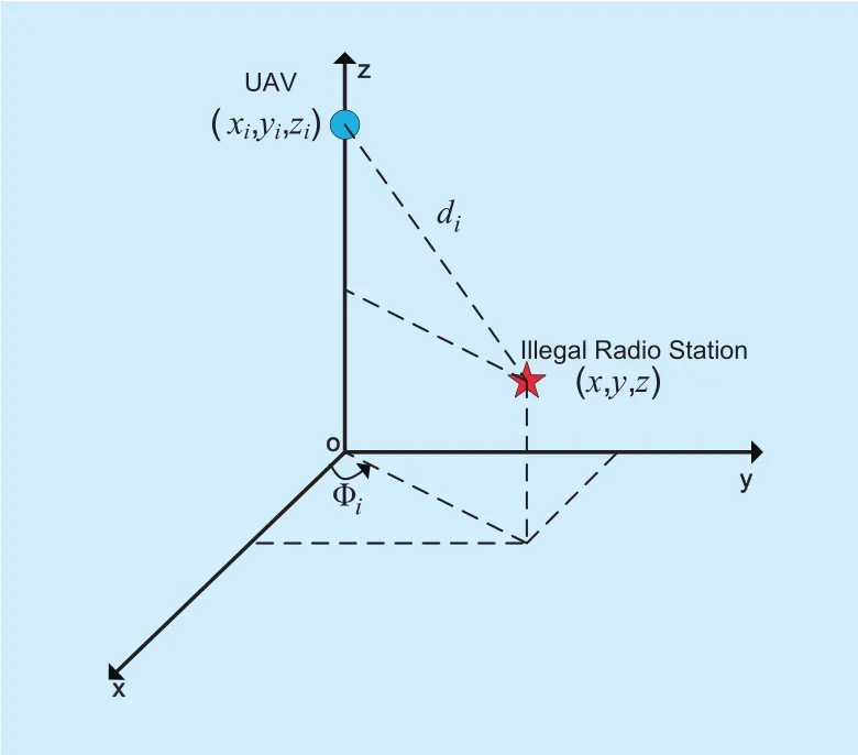
Fig. 2. The relative position of an IRS and a UAV.

The k-th power value received by the directional antenna (in direction θ ) in the i-th time interval is given by
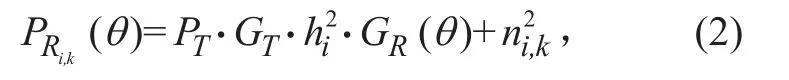
where PTis the transmit power; GTand hiare the transmit antenna gain and the channel power gain in time interval i, respectively;GR()θ denotes the receive antenna gain for a given azimuth θ; ni,kdenotes a white noise conforming to a normal distribution with a mean value of 0 and a variance of σ2.
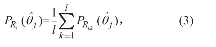
By rotating its airframe, the rotary-wing UAV equipped with a directional antenna can measure RSS values in u directionsas shown in figure 3(where u = 36). To reduce the RSS error caused by the random noise, in each direction,multiple RSS measurements are averaged,yielding
We assume that the initial position of the UAV is (0, 0), i.e. x1= 0 and y1= 0. Without loss of generality, we assume that the coordinate system can be established, such that for i > 1, it always holds that xi> 0 andyi> 0.Therefore, given the UAV’s position (xi-1, yi-1)in the (i-1)-th time interval, the UAV’s position in the i-th time interval can be obtained as


where (xi,yi) is the UAV position in the i-th time interval which is obtained after the UAV takes (i- 1) actions; wi-1is the step size of the UAV in the (i - 1)-th time interval. In (4) and(5), θi-1denotes the direction selected by the UAV in the (i - 1)-th time interval, and the UAV flies towards θi-1in the (i - 1)-th time interval. The θi-1can be updated over time intervals, by performing the direction-aware Q-learning algorithm proposed in the following Section III-A.
III. DIRECTION-AWARE Q-LEARNING
Thanks to the directional antenna, the UAV can measure average RSS values in different directions. Ideally, in the absence of noise, the direction corresponding to the largest average RSS is the direction of the IRS. However, due to RSS signal noises, the UAV may select inappropriate directions, leading to errors in xiand yi. To address this problem, we propose a direction-aware Q-learning algorithm for online trajectory planning.
3.1 States and actions of the UAV
For the UAV, we define eight states s∈{1,2,…,8}as listed in Table I, which are essentially indices of quantized RSS values. The UAV’s state s in time interval i depends on the largest average RSS value among the average RSS values measured in all directions. Moreover, for the UAV, we define u actions a ∈{ a1,a2,… ,au}, corresponding to the u directionsas shown in figure 3. For example, if the u-th action is selected,the UAV will fly towards
3.2 Direction-aware Q-value update
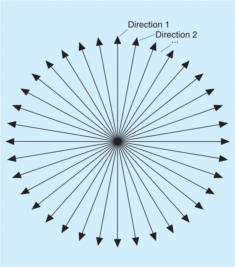
Fig. 3. u = 36 directions. The UAV is in the center of the circle.
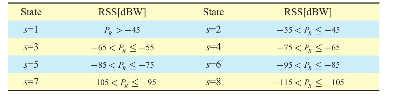
Table I. 8 states of the UAV corresponding to the value of the RSS.

where Q(s,a) collects Q-values of the state-action combinations. In time interval i, PRiis the largest value among u average RSS values measured in the u directions. In the above equation, the state s corresponds to the largest averaged RSS value PRi-1in time interval (i -1). Equation (6) means that in state s, if the Q-value Q(s,a) with respect to a certain action a is greater than Q values with respect to other actions, the best action should bea= .Afterwards, the Q-values which evaluate the quality of state-action combinations are updated.
We now elaborate on the update of the Q-value, which evaluates the quality of a state-action combination, in time interval i. In the proposed direction-aware Q-learning algorithm, we modify the original Q-vaule update function [13] and reformulate the Q-value update function as
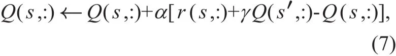
where Q(s,:) collects Q-values of all actions corresponding to state s. The state s in (7)represents a current state which corresponds to the largest averaged RSS value in each time interval. Moreover, Q(s′,:) is the Q-value of all actions in state s′, and s′ is the state in time interval i. Specifically, state s′ corresponds to the largest averaged RSS value PRiin time interval i.
In (7), the parameter α∈[0,1] denotes the learning rate, which controls the learning speed. The parameter γ∈[0,1] is a discount factor, which determines the importance of future rewards. For γ=0, the system is myopic and merely takes into account results of the current action. By contrast, as γ closes to 1,future rewards play an important role in determining optimal actions.
The function r(s,:) in (7) denotes the immediate rewards for all actions in state s. Given an action a (i.e. direction), the immediate reward is evaluated by

where PRi(a ) is the RSS measured in the i-th time interval and the direction corresponding to action a) is the RSS measured in the(i - 1)-th time interval and the direction corresponding to action aˆ; aˆ is the action selected in the second slot of time interval (i - 1) by performing (6).
It is worth noting that in (7), Q(s,:), r(s,:)and Q(s′,:), instead of Q(s,a), r(s,a) andin the original Q-learning [24],are exploited. As shown in (7), Q-values with respect to multiple directions can be simultaneously updated. It means that multiple directions can be simultaneously tested and penalized, such that the best direction can be determined. By this means, the proposed direction-aware Q-learning can converge quickly.
The Prince reached the palace in safety, but was so dazzled at first by the Princess s beauty, which far surpassed his expectations, that he was quite dumb for a time
3.3 The stopping criterion and summary of the direction-aware Q-learning
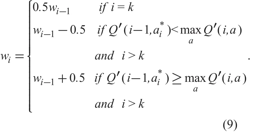
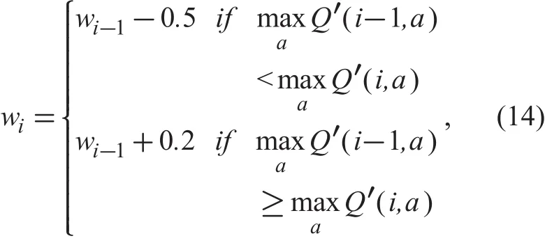
We now discuss the stopping criterion of the localization procedure. As the transmit power of most IRSs is higher than 20 watts, a threshold m is exploited to decide whether the UAV is close to the IRS. In time interval i, if the largest average RSSmeans that the UAV’s position is very close to the IRS. When the UAV reaches the area near the IRS, the SNR can be adequately high, and the UAV will fly around the IRS.In order to check if the UAV flies around the IRS, we select o coordinates of the UAV (xi-o+1, yi-o+1), (xi-o+2, yi-o+2), ··, (xi, yi)during the (i−o+1)-th time interval to i-th time interval. In the presence of the UAV being close to the IRS, the trajectory flying through these o coordinates can form a polygon, where the centroid of the polygon isdistances between the centroid and these coordinates of the UAV in different time intervals are designated as dc,i-o+1, dc,i-o+2, · · ·, dc,i. If dc,i-o+1, dc,i-o+2, · · ·, dc,iare less than a threshold rak, these coordinates of the UAV are within a circle with a center of (xc,yc) and a radius of rak, and we declare that the UAV is flying around the IRS. Afterwards, the step size wiof the UAV is gradually decreased by the rule as shown in (9) until wivanishes.k represents the index of the time interval in which max( dc,i-o+1,dc,i-o+2,… , dc,i)<rak is satisfied for the first time; Q′(i,a) is the value of Q(s,a) in time interval i, Q′(i-1,a*i) is the value of Q(s,a*i) in time interval (i - 1).
The direction-aware Q-learning is summarized in Algorithm 1. The Q-values of each state-action pair stored in a 8-by-u matrix are initialized to zero, where u stands for the number of directions.
IV. SIMULATION RESULTS
In the simulations, three types of antenna direction characteristics (as shown in figure 4) are considered for the directional antenna-based localization. The normalized pattern functions of three typical antennas, i.e., antenna type A, B and C, are characterized by (10),(11) and (12) respectively as follows:

Additionally, the k-th power value received by the directional antenna in the i-th time interval is given by:

represents the gain of receiving antenna for elevation ϕ and azimuth θ; η is the antenna efficiency; λ indicates the wavelength in meters;L is the system loss factor unrelated to propagation (L≥1).
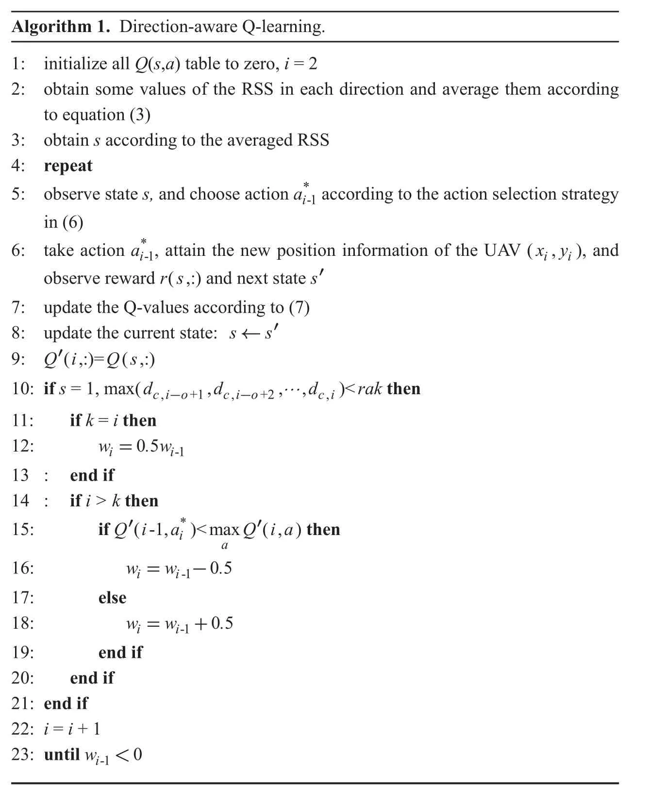
Algorithm 1. Direction-aware Q-learning.1: initialize all Q(s,a) table to zero, i = 2 2: obtain some values of the RSS in each direction and average them according to equation (3)3: obtain s according to the averaged RSS 4: repeat 5: observe state s, and choose action a*i-1 according to the action selection strategy in (6)6: take action a*i-1, attain the new position information of the UAV (x,y)i i, and observe reward r(s,:) and next state s′7: update the Q-values according to (7)8: update the current state: s← s′9: Q i Qs′(,:)= (,:)10: if s = 1, max( , , , )<d d d rak cio cio ci, +1 , +2 ,-- … then 11: if k = i then 12: w .w i i=05 -1 13 : end if 14 : if i > k then 15: if Q i a Q ia*i a then 16: w w .′(-1, )<max ′(,)-1 05 17: else 18: w w .i=ii=i+-1 05 19: end if 20: end if 21: end if 22: i = i + 1 23: until wi-1<0

Fig. 4. Three types of antenna radiation patterns.
In the simulations, the transmit power PTat the IRS is set as 20 W; both the transmit antenna gain GTand the antenna efficiency η are 1;the wavelength λ is 3m; and L is 1. The initial position of the UAV is (0, 0, 250m) and the geographical position of the IRS is (1000m,1000m, 50m). The learning rate α is 0.9, and the discount factor γ is 0.1. The number of RSS measurements in the same direction is 20.Type C antenna is exploited at the UAV, and the action set with 36 actions is used, unless otherwise stated. The initial step size w1is set as 10 m. We assume that in the most pessimistic situation, the initial direction of the UAV is opposite to the direction of the target.
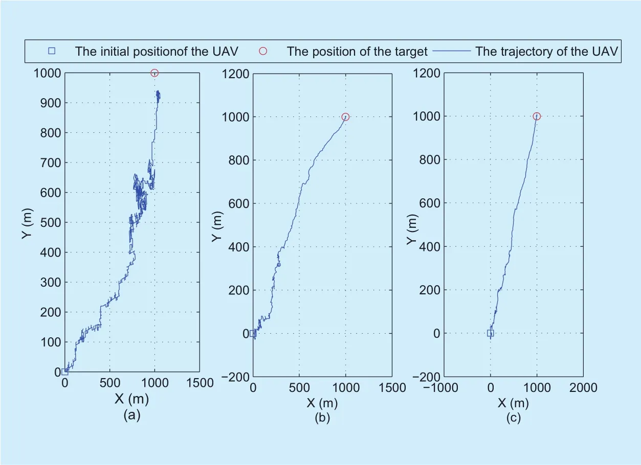
Fig. 5. The trajectories of the UAV achieved by the three localization schemes. (a)The trajectory achieved by the Q-learning for omnidirectional antenna. (b) The trajectory achieved by the maximum RSS for directional antenna. (c) The trajectory achieved by the direction-aware Q-learning.

Fig. 6. The comparison of the three localization schemes in aspect of the percentage of the localization error being less than 100m.
To evaluate the performance of the proposed localization scheme, we compare it with the two baseline schemes, i.e., Q-learning for omnidirectional antenna and maximum RSS for directional antenna. In the first baseline scheme, when PRi< m ′ (m′ is a threshold and m′ < m), if the average RSS in time interval(i - 1) is smaller than that in time interval i,the UAV will fly to ( xi+1,yi+1); otherwise, the UAV should fly back to ( xi-1, yi-1), and the Q-value matrix should remain the same as that in the time interval (i-1). The stopping criterion of this scheme is: i) PRi> m, and wi<0 or ii)> m, wi<c, and> m′, where c denotes a threshold related to the step size and is set as half of the initial step size in the simulations; m′ represents a larger value among previous average RSS measurements. In the simulations, we set m′ as an average value of the fourth and fifth largest values. In the second baseline scheme, the UAV flies towards the direction with respect to the maximum RSS value. The stopping criterion of the scheme is the same as that of the proposed localization scheme. The rules for the UAV reducing its step size in the two baseline schemes are shown in (14) and (15), respectively.
where Q′(i,a) is the value of Q(s,a) in time interval i.

Figure 5 illustrates the UAV trajectories achieved under the three localization schemes.In figure 5, the receive SNR at the initial position of the UAV is -10dB. It can be drawn from the comparison of figure 5(a)-(c) that the Q-learning for omnidirectional antenna can not quickly locate the IRS, and the trajectory of the UAV is much longer than those of the other two schemes. Moreover, it is shown that the trajectory achieved by the maximum RSS for directional antenna is tortuous when the UAV is far from the target, while the trajectory is almost a straight line when the UAV is close to the target. This is due to the fact that as the UAV approaches the target, the SNR increases,which causes the smoother trajectory. By contrast, it is shown that the trajectory achieved by the direction-aware Q-learning can be smoother than that achieved by the maximum RSS for directional antenna.
Figure 6 studies the percentage of the localization error being less than 100m versus the receive SNR at the initial position of the UAV. It is shown that when the receive SNR at the initial position of the UAV ranges from-14dB to 0dB, the direction-aware Q-learning and maximum RSS for directional antenna can always achieve the localization error is less than 100m. By contrast, the localization error performance achieved by the Q-learning for omnidirectional antenna is low at the low SNR region. For the SNR lower than -10dB,the localization error performance achieved by the Q-learning for omnidirectional antenna is much lower. Therefore, when the SNR is lower than -10dB, we omit the performance achieved by the Q-learning for omnidirectional antenna in the following simulations.
Figure 7(a) investigates the localization root-mean-square-error (RMSE) achieved by different schemes as a function of the receive SNR at the initial position of the UAV. Figure 7(a) indicates that the localization accuracy of the Q-learning for omnidirectional antenna is sensitive to the receive SNR at the initial position of the UAV. It can be seen from figure 7(a) that the localization RMSE achieved by the Q-learning for omnidirectional antenna is much higher than that achieved by the other two localization schemes.
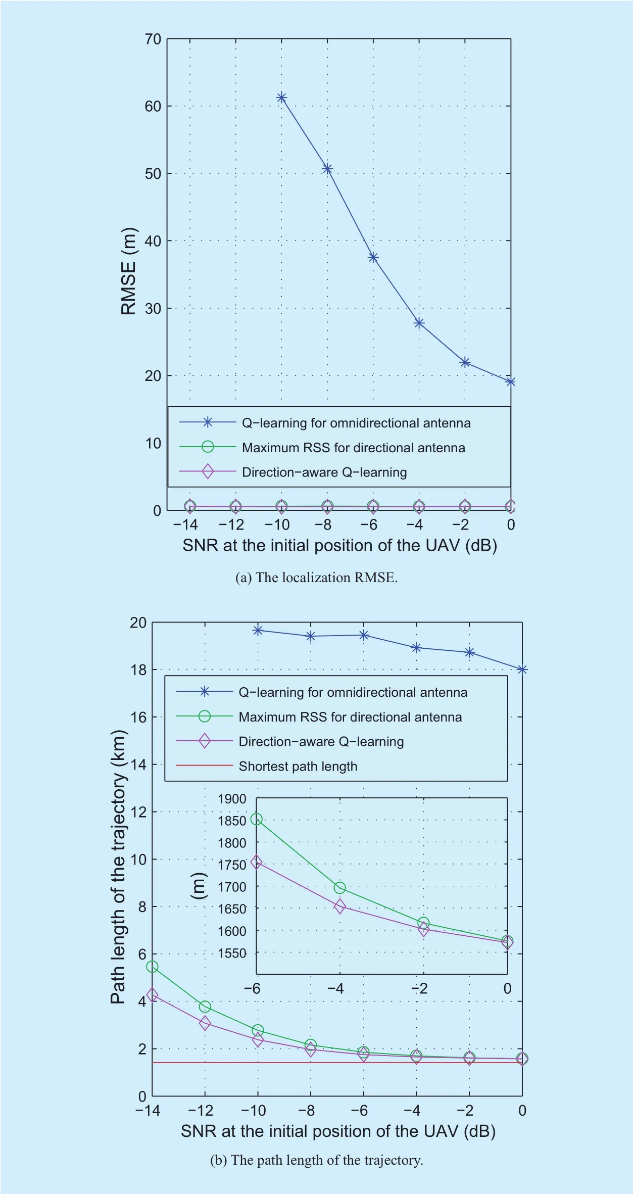
Fig. 7. The performance comparison of the three localization schemes.
Figure 7(b) draws a comparison of the path lengths of trajectories achieved by the three localization schemes. It is shown that as the receive SNR at the initial position of the UAV increases, there is a downward trend in the path length. It can be seen that the path length obtained by the direction-aware Q-learning is significantly shorter than that achieved by the two baseline localization schemes, especially in the case of the low receive SNR at the initial position of the UAV.
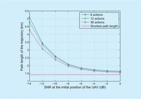
Fig. 8. The path length of the trajectory achieved by the direction-aware Q-learning when varying the number of actions.
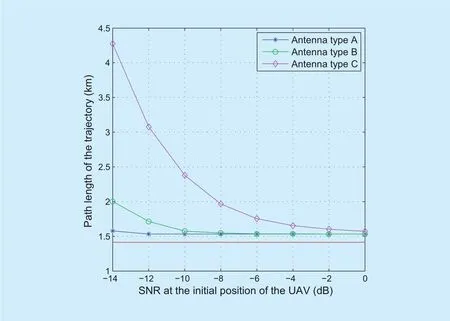
Fig. 9. The path length of the trajectory achieved by the direction-aware Q-learning in the presence of various antenna radiation patterns.
We evaluate the path length of the trajectory achieved by the direction-aware Q-learning when varying the number of actions, i.e.,directions. As depicted in figure 8, when the receive SNR at the initial position of the UAV increases, the path length of the trajectory decreases. It is shown that the scheme with 8 actions yields the longest trajectory, while the scheme with 36 actions offers the shortest trajectory. It can be drawn from the above observations that: by increasing the number of actions, the localization efficiency can be enhanced.
In figure 9, we investigate the path length of the trajectory achieved by the direction-aware Q-learning in the presence of Type A, B and C antenna radiation patterns. We can draw the conclusion that by exploiting an antenna with a narrow main lobe, the direction-aware Q-learning algorithm can yield a shorter trajectory.
V. CONCLUSION
In this paper, we have studied the problem of positioning IRSs. In the proposed scheme,the IRS is localized by processing RSS values measured by a UAV equipped with a directional antenna, without the knowledge of the transmit power of the IRS, the channel model and the RSS signal noise model. To solve the localization problem, we have proposed a direction-aware Q-learning, so as to fully take advantage of the directional antenna. We also investigate two baseline schemes. In one scheme, the IRS is located by a UAV equipped with an omnidirectional antenna. Q-learning is applied to process the measured RSS values and locate the IRS. In the other scheme, the UAV is equipped with a directional antenna,while the direction the UAV flies towards is the direction with respect to the maximum RSS value. Numerical results show that the proposed localization scheme outperforms the two baseline schemes, especially in the case of the low receive SNR at the initial position of the UAV.
ACKNOWLEDGEMENT
This work is supported by China NSF Grants (61631020), and the Fundamental Research Funds for the Central Universities(NP2018103, NE2017103, NC2017003).
杂志排行

China Communications的其它文章
- Pedestrian Attributes Recognition in Surveillance Scenarios with Hierarchical Multi-Task CNN Models
- Cost-Aware Multi-Domain Virtual Data Center Embedding
- Statistical Analysis of a Class of Secure Relay Assisted Cognitive Radio Networks
- Moving Personal-Cell Network: Characteristics and Performance Evaluation
- A Novel 3D Non-Stationary UAV-MIMO Channel Model and Its Statistical Properties
- Mode Selection for CoMP Transmission with Nonideal Synchronization