Effect of insufficient tunnel crown thickness on the post-tensioned concrete lining of the Yellow River Crossing Tunnel and its strengthening schemes
2018-10-17QinGanCaoShengrongLaiXuYangFan
Qin Gan Cao Shengrong Lai Xu Yang Fan
(State Key Laboratory of Water Resources and Hydropower Engineering Science, Wuhan University, Wuhan 430072, China)
Abstract:The effect of deficiency in tunnel crown thickness on the Yellow River Crossing Tunnel with post-tensioned concrete inner lining was investigated by the elasto-plastic finite element method. Changes in the deformations and circumferential stresses of the post-tensioned concrete inner lining with the gradual decrease of the tunnel crown thickness were compared, and the potential bearing risk of insufficient tunnel crown thickness for the Yellow River Crossing Tunnel was revealed. Based on the finite element calculation results of circumferential stresses under different defective cases, the corresponding reinforcement schemes were proposed. The calculation results show that the inner lining can still maintain a satisfactory stress state when the tunnel crown thickness is equal to or greater than 0.28 m. When the tunnel crown thickness decreases below 0.28 m, the external surface of the crown and internal surface of the crown’s adjacent areas may be under tension. The tension stresses will incrementally increase and ultimately exceed the tensile strength of the inner lining concrete as the tunnel crown thickness further decreases gradually. Then, the Yellow River Crossing Tunnel cannot operate normally, and severe cracking, leaking or even failure may occur. When the tunnel crown thickness is equal to or greater than 0.28 m, the reinforcement suggestions are that the void spaces between the inner lining and the outer lining should be back-filled with concrete. When the tunnel crown thickness is less than 0.28 m, the inner lining should be reinforced by steel plates after concrete back-filling.
Keywords:post-tensioned concrete linings; tunnel crown thickness; stress redistribution; finite element analysis; tunnel reinforcement; Yellow River Crossing Tunnel
As part of hydropower schemes, the role of pressure tunnels has become significantly important in maintaining sustainability of a hydropower operation. To improve the water impermeability of pressure tunnels, traditional steel linings are often used, but the steel plate is very expensive[1]. With the development of the prestress technique, the need for a more economical design has caused a shift from steel to other alternatives, such as post-tensioned concrete linings. For tunnels subjected to high internal water pressure, the concrete can be held in a fully compressed state by introducing prestress, ensuring stability and water-tightness[2-3]. The first tunnel with post-tensioned concrete lining was constructed at Piastra-Andonno in Italy in 1974, and multiple tunnels have followed[4].
Due to imperfect concrete casting or an inefficient pumping system, the crown of the tunnel may not be completely filled[5]and evidence of this problem can be readily found in the technical literature[6-7]. Many negative consequences can ensue due to deficiency in tunnel crown thickness. For example, Bian et al.[8]reported a wide range of cracking occurred in concrete lining at the crown of the high-pressure bifurcation in the water-filled test of bifurcation tunnel at Huizhou Pumped Storage Power Station and the deficiency in concrete thickness in the crown was the primary triggering factor for lining cracking. At the same time, significant void spaces may remain between the rock surface and the concrete lining when the thickness of the tunnel crown is insufficient. The negative consequences of voids can appear as minor surface corrosion of tunnel appurtenances, major deterioration of the lining with associated reduced load carrying capacity and even failure of the lining[9-10]. In addition, the final shape of the tunnel boundary will be different from the theoretical one due to the deficiency in tunnel crown thickness. Barpi et al.[11]and Son et al.[12]highlighted that the irregular shape of a tunnel boundary induces stress concentration in the lining, which can result in cracking and sometimes in local collapses.
Deficiency in tunnel crown thickness can lead to lining cracking or even failure of the lining. However, most of the above achievements have focused on the reinforced concrete linings or plain concrete linings. Little attention has been paid to the post-tensioned concrete linings. Due to the construction procedure differences between them, deficiency in tunnel crown thickness may cause new problems for post-tensioned concrete linings. To investigate the impact of deficiency in tunnel crown thickness on pressure tunnels with post-tensioned concrete linings, the Yellow River Crossing Tunnel in the middle route of the South-to-North Water Transfer Project has been adopted by this study as a reference case. A series of simplified cross sections of the post-tensioned lining with insufficient tunnel crown thickness are then defined. Two working conditions, one is completed cable tensioning (CCT) and the other is water in the tunnel with the design water pressure (DWP), are analyzed.
1 Introduction of Yellow River Crossing Tunnel
The Yellow River Crossing Tunnel is the most impressive and important building in the entire middle route of the South-to-North Water Transfer Project. The total length of the Yellow River Crossing Tunnel is 3 450 m. The excavation diameter of each tunnel is 8.7 m, and the design flow rate is 265 m3/s. The longitudinal profile of the Yellow River Crossing Project is shown in Fig.1.

Fig.1 Longitudinal profile of the Yellow River Crossing Project (unit: m)
The composite lining of Yellow River Crossing Tunnel is composed of three components: The outer lining, the membrane, and the inner lining. The outer lining is composed of precast segments made of reinforced concrete. Each circular ring consists of 6 conical regularly shaped blocks and a small-sized key block. The thickness of each precast concrete ring is 0.4 m. The membrane is located between the outer lining and inner lining and is 6 mm thick. The membrane is wrapped around the circumference of the tunnel for approximately 300° by a machine. The membrane is also composed of three parts. The middle portion is the water-resisting layer, and the two sides are the elastic permeable layer. The cross section of the tunnel lining is illustrated in Fig.2.
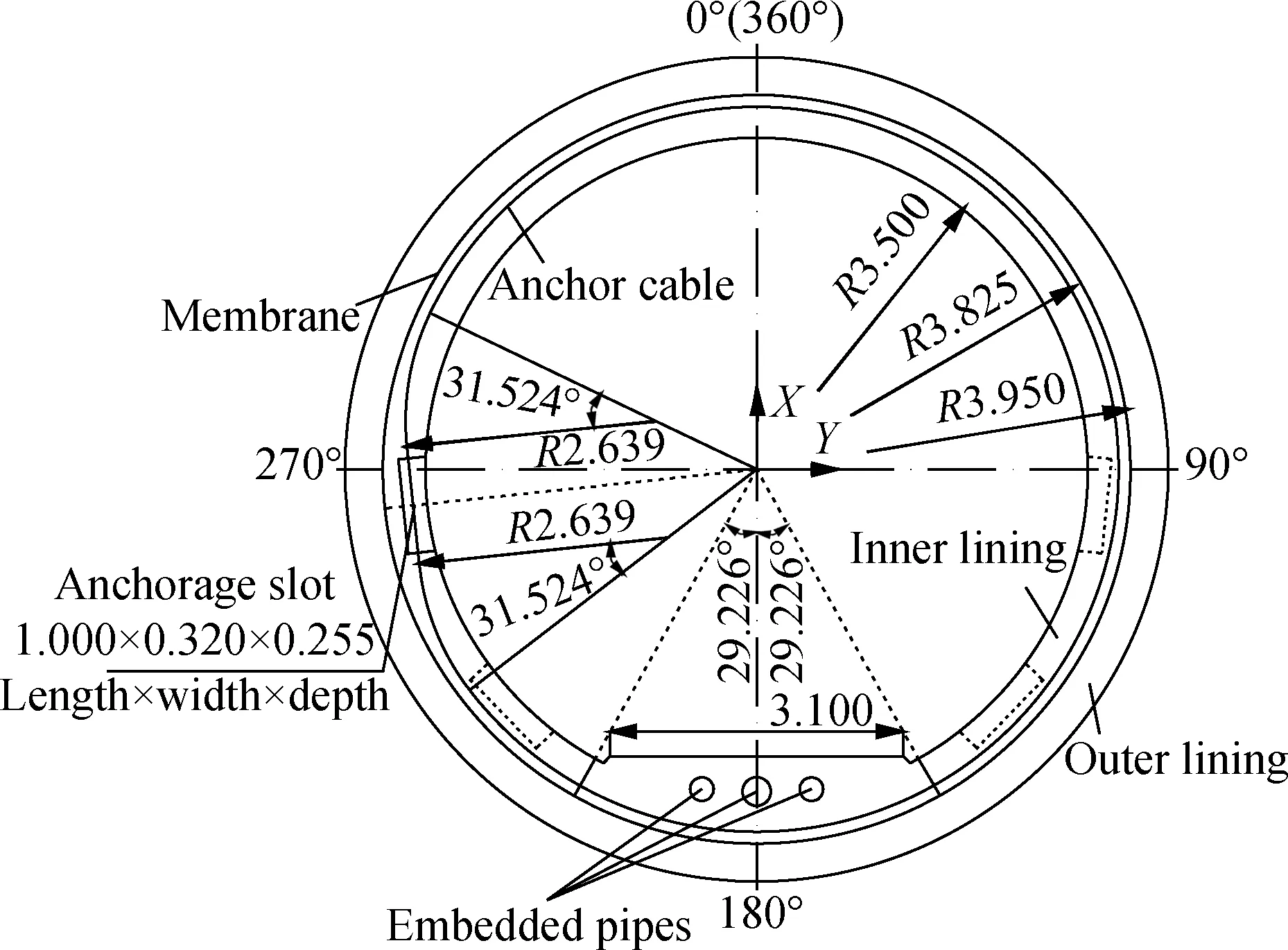
Fig.2 Schematic of the cross section of the tunnel lining (unit: m)
The inner lining is a cast-in-situ reinforced concrete, which is post-tensioned with looped boned anchor cables. The inner lining is of 7 m in inner diameter, 7.9 m in outer diameter and 0.45 m in thickness. After the concrete pouring is completed and the concrete reaches a certain strength, the prestressed anchor cables begin to be tensioned. A prestressed anchor cable includes 12 steel strands. Each steel strand contains 7Φ5 high strength and low relaxation steel wires. The anchorage slot is the location prepared for tensioning and locking off the anchor cables. The center line of the anchorage slots are respectively located atθ=96°, 134°, 226° and 264°, andθis the angle measured clockwise from the vertical plane. The anchorage slots are distributed in the lower semicircle of the inner lining with an axial spacing of 0.45 m. The distribution of the anchorage slots is shown in Fig.3.
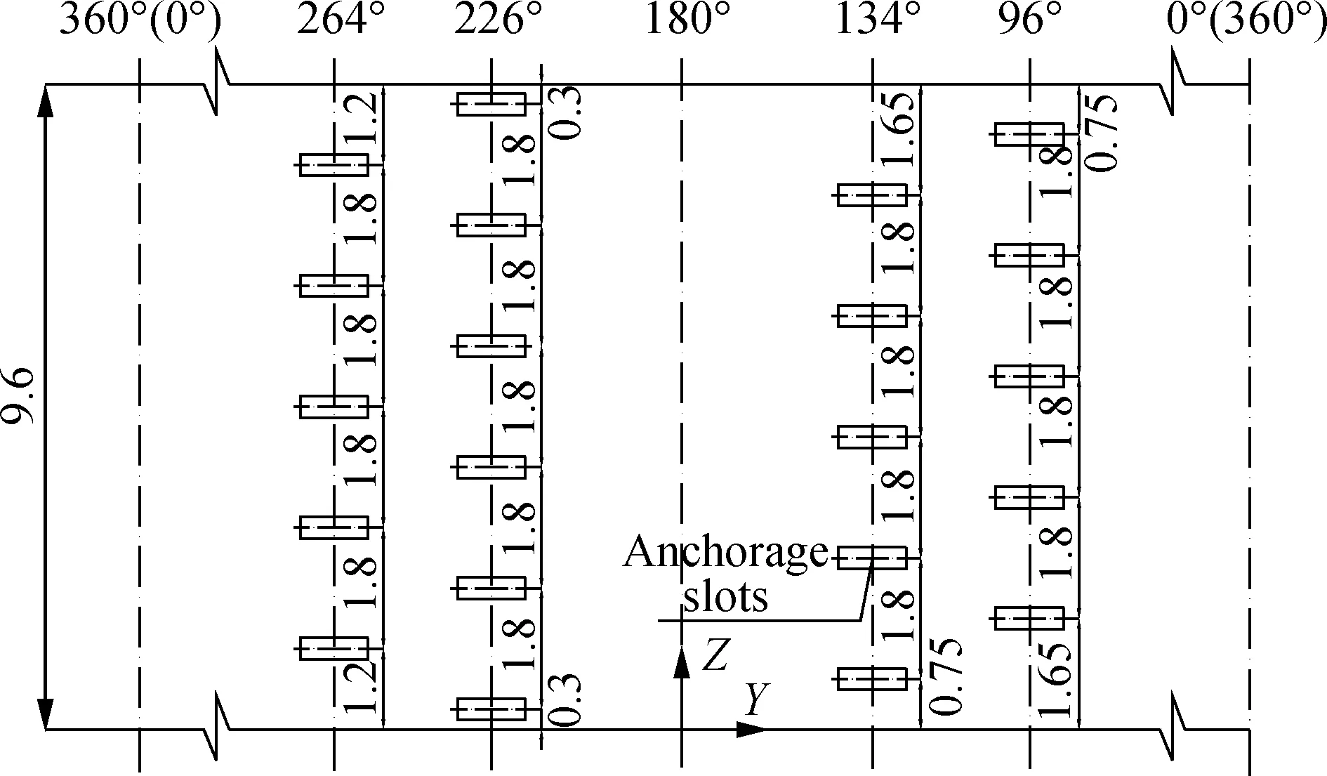
Fig.3 Layout of the internal surface of the inner lining (unit: m)
2 Finite Element Model
2.1 Model details
The simulations are performed using the finite element computer program ANSYS 12.0. The calculation model is created by taking a length of 9.6 m along the axial direction. Eight-noded solid elements (SOLIDE45) are used to simulate the soil, and the soil is approximated as elasto-plastic following the Drucker-Prager failure criterion. Eight-noded solid elements (SOLIDE65) are used to simulate the lining concrete and the membrane. Two-noded link elements (LINK8) are used to simulate the prestressed anchor cables and reinforcing bars in the inner lining. A typical finite element mesh of the Yellow River Crossing Tunnel is shown in Fig.4.
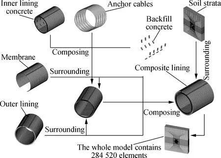
Fig.4 Three-dimensional FE models of the Yellow River Crossing Tunnel
The inner lining bears the internal water pressure, and the outer lining bears the external water pressure and earth pressure, respectively[13]. Thus, the outer lining is regarded as a physical boundary and is simplified as a perfectly uniform rigid ring in the model. The material properties for the support are listed in Tab.1. The whole numerical model contains 284 520 elements and 265 485 nodes.
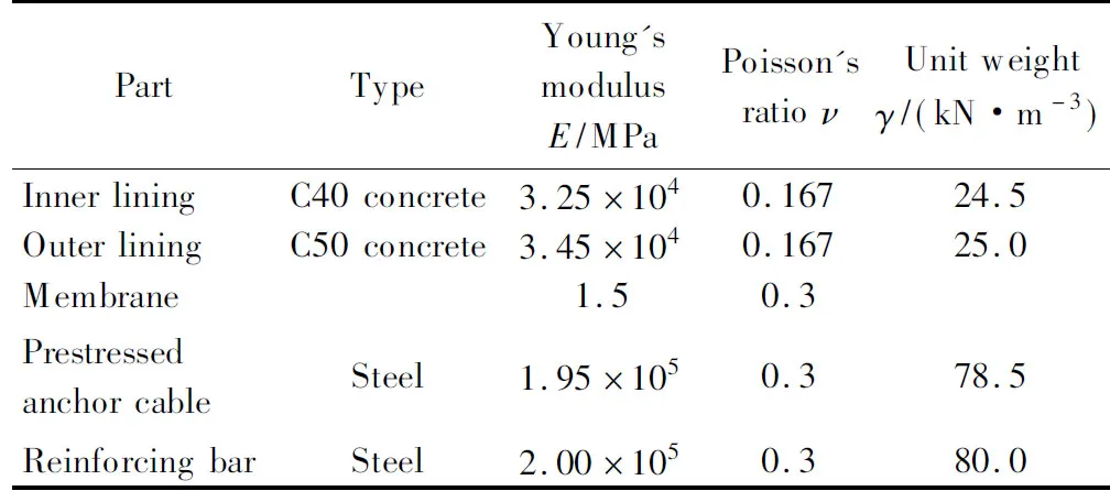
Tab.1 Material properties
The main characteristics of the composite lining are the existence of numerous contact interfaces, including interfaces between the internal surfaces of the membrane and the external surfaces of the inner lining and interfaces between the tunnel excavation boundary and the external surfaces of the outer lining. The contact elements CONTAC174 and TARGE170 are used to simulate the complex interface interaction. The contact behavior in the radial direction is simulated as a “hard contact”, which can transmit compressive stresses but cannot transmit radial tensile stresses, so that the two surfaces would have been separated when the pressure between them approached zero[14]. The Coulomb friction model is used to limit the tangential tractions. Here, a value of 0.3 is selected as the friction coefficient and the penalty method is used as the contact algorithm[15].
In this study, a series of simplified cross sections of the inner lining with insufficient tunnel crown thickness are introduced, as shown in Fig.5.Trepresents the actual thickness of the crown, andThas been selected in six cases in this paper, namely,T=0.45, 0.40, 0.325, 0.28, 0.22, 0.16 m. It should be noted that the concrete can support the anchor cables as they are tensioned whenT=0.45, 0.40, 0.325 m. However, whenT=0.28, 0.22, 0.16 m, anchor cables located at the crown will hang in the void, as shown in Fig.5(b). Since these partial anchor cables are not supported by concrete, it is assumed that they will be straight lines once they are tensioned, as shown in Fig.5(a).

(a)
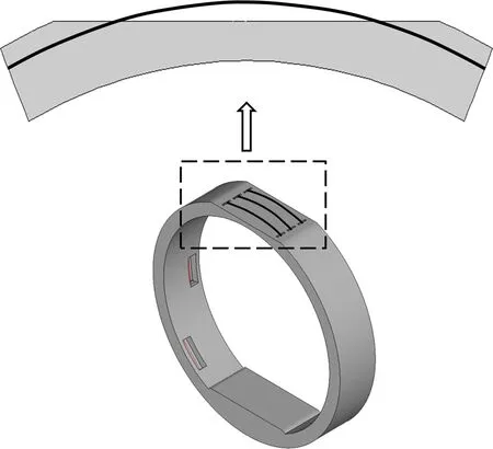
(b)Fig.5 Schematic of the simplified cross section of the inner lining. (a) After tensioning of the anchor cable; (b) Before tensioning of the anchor cable
2.2 Effective prestress
The effective prestress is not constant along the length of the anchor cables due to prestress losses. Many factors can affect the prestress loss values. The prestress losses considered in this paper mainly includeσl1caused by anchorage deformation and reinforcement retraction,σl2caused by friction between the anchor cable and the duct,σl3caused by stress relaxation of the prestressed anchor cable, andσl4caused by shrinkage and creep of concrete[16]. The calculation ofσl1,σl3, andσl4can follow the formulae recommended by the Code for Design of Concrete Structure[17].
It is noted that the shape of anchor cables at the crown is curved whenTis equal to or greater than 0.325 m and is a straight line whenTis less than 0.325 m. Therefore, the prestress loss values caused by the friction between the anchor cable and the duct should be divided into two cases. In case one, the thickness of the tunnel crown is equal to or greater than 0.325 m and the concrete at the crown can support the anchor cables when they are tensioned. Then, as ecommended by the Code for Design of Concrete Structure[17],σl2can be expressed as
σl2=σcon(1-e-(κrc+μ)φ)
(1)
whereμis the friction coefficient between the prestressed anchor cable and the duct;kis the wobble friction coefficient per meter of anchor cable;rcis the curvature radius of the prestressed anchor cable;σconis the tension control stress;φis the cumulative angle change between the tensioning position and the calculation section.
In case two,the thickness of the tunnel crown is less than 0.325 m, as shown in Fig.6. Partial anchor cables at the crown will hang in the void and will be assumed to be straight lines once they are tensioned. Theσl2between the tensioning position and locationAcan still be expressed as Eq.(1). Consequently, the stress of the anchor cable at locationAand locationBcan be calculated by the following equations:
σA=σcone-(κrc+μ)φA
(2)
σAB=σAe-μβ
(3)
σB=σABe-μβ
(4)
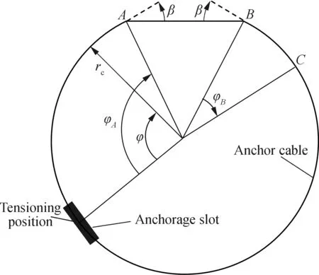
Fig.6 Shape of the anchor cable after being tensioned whenT<0.325 m
Then,the prestress lossσl2after locationBcan be expressed as
σl2=σB(1-e-(κrc+μ)φB)
(5)
whereφAis the cumulative angle change between the tensioning position and locationA;φBis the cumulative angle change between locationBand the calculation section;βis the angle between the tangent of the anchor cable at locationAand the horizontal line; andσABis the stress of the anchor cable betweenAandB.
Then,the final effective prestressσpecan be expressed as
σpe=σcon-σl1-σl2-σl3-σl4
(6)
The falling temperature method is used to apply an effective prestress on the anchor cable elements. Converting the effective prestress into the temperature load and then applying the temperature load to the anchor cable elements, the temperature load can be expressed as
(7)
wheretis the temperature load applied to the anchor cable elements;σpeis the effective prestress of the anchor cable;Eis the elastic modulus of the anchor cable;αis the expansion coefficient of the anchor cable.
2.3 Computational process
Two working conditions, of which one is completed cable tensioning (CCT) and the other is water in the tunnel with the design water pressure (DWP), are analyzed. Under the CCT working condition, the finite element model is affected by the effective prestress, gravity of the structure, and external water pressure. Under the DWP working condition, the finite element model is affected by the effective prestress, gravity of the structure, external water pressure, and internal water pressure. The external water pressure in the horizontal line of the tunnel centre is 0.323 MPa. The internal water pressure in the tunnel centre is 0.517 MPa. Separate calculations of water and earth pressures can be used when the tunnel is covered by sandy soil[18]. Therefore, the external water pressure is directly applied on the segmental lining and the effective unit weight of the soil is used.
3 Analysis of the Numerical Results
3.1 Deformations of the inner lining
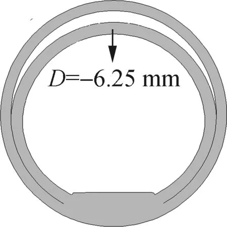
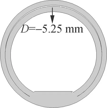
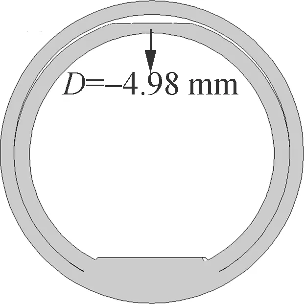
As we known, failure is likely to occur in the large deformation parts of lining concrete; thus, deformation analysis is helpful to investigate the reason for lining cracking. The calculated deformations of the lining under the CCT working condition and DWP working condition are shown in Fig.7 and Fig.8, which also reveal the radial displacementsDat the crown of the inner lining. Positive displacement represents direction toward outward of the inner lining and negative displacement denotes direction toward inward of the inner lining.
According to Fig.7(a), when the tunnel crown thick-ness meets the design requirements, deformations of the inner lining are inward at the crown and outward at the springline. Then the shape of the tunnel is oval with its major axis parallel to the horizontal direction. As shown in Figs.7(b) to (d), the inner lining displacements at the crown are inward, with magnitudes -6.39 mm forT=0.40 m, -6.95 mm forT=0.325 m, and -6.87 mm forT=0.28 m. Consequently, the above comparison indicates that deficiency in tunnel crown thickness can induce increase of inward movements at the crown when the tunnel crown thickness is equal to or greater than 0.28 m.
(a)(b)(c)
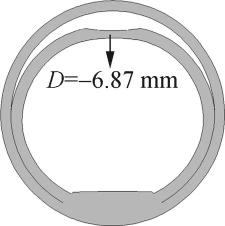
(d)(e)(f)Fig.7 Deformations of the inner lining under the CCT working condition. (a)T=0.45 m; (b)T=0.40 m; (c)T=0.325 m; (d)T=0.28 m; (e)T=0.22 m; (f)T=0.16 m
(a)(b)(c)
(d) (e)(f)Fig.8 Deformations of the inner lining under the DWP working condition. (a)T=0.45 m; (b)T=0.40 m; (c)T=0.325 m; (d)T=0.28 m; (e)T=0.22 m; (f)T=0.16 m
In contrast, when the tunnel crown thickness is less than 0.28 m, a different trend is found. As indicated in Fig.7(f), the radial displacement at the crown is -4.92 mm whenT=0.16 m. Compared withT=0.45 m, there is an evident decrease of 23.1%. This behavior occurs because the tunnel crown concrete is thin and squeezed by the anchor cables on both sides, which results in an obvious bulge to the outer lining at the crown. Here, the shape of the tunnel is still oval, but with its major axis parallel to the vertical direction. Similar conclusions can also be obtained under the DWP working condition. As indicated in Fig.8(f), the radial displacement at the crown is -0.24 mm whenT=0.16 m. Compared withT=0.45 m, there is an evident decrease of 95.4%, which shows a substantial increase of deformation at the crown.
3.2 Circumferential stresses of the inner lining
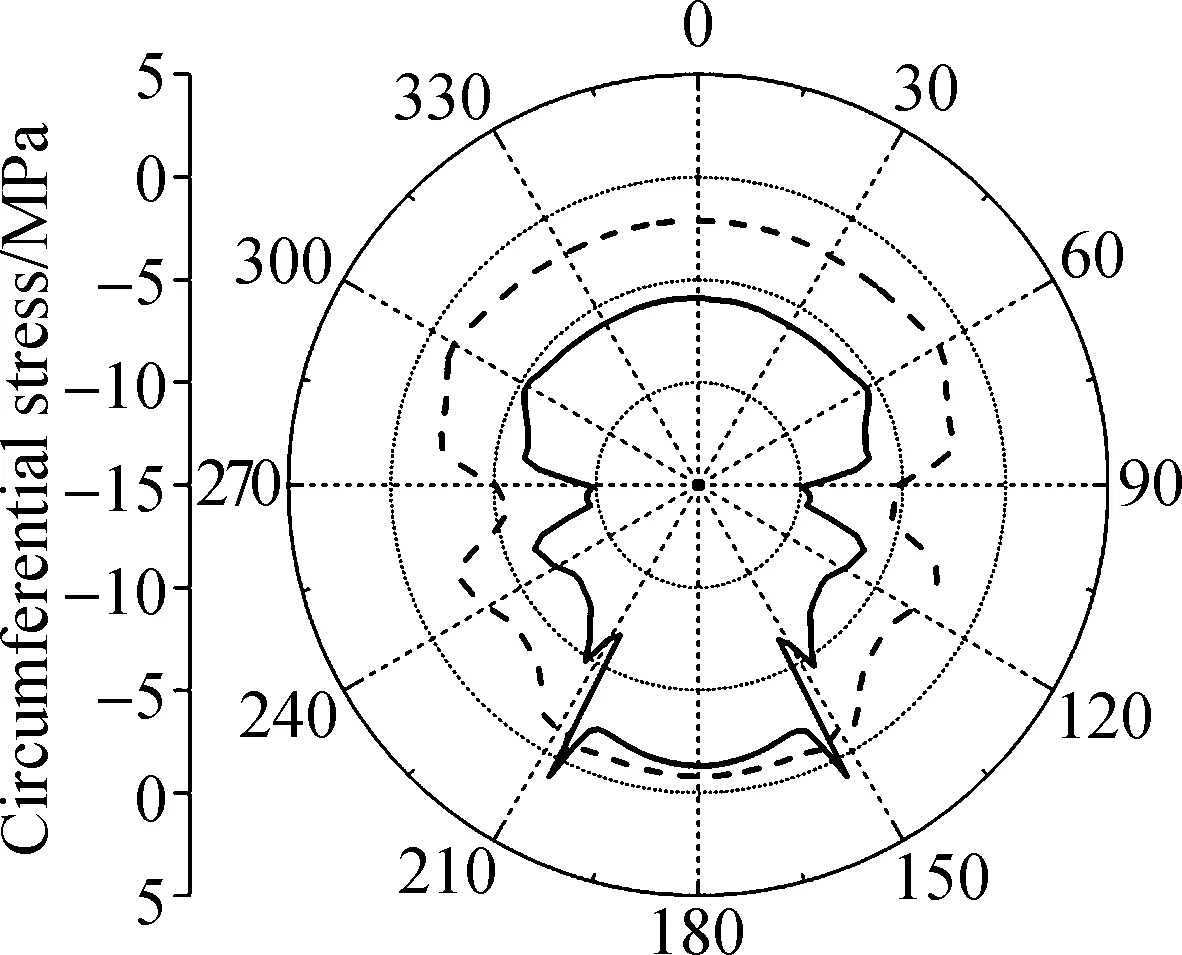
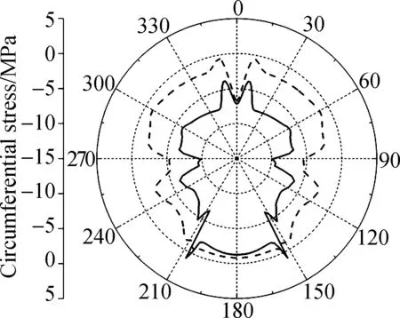
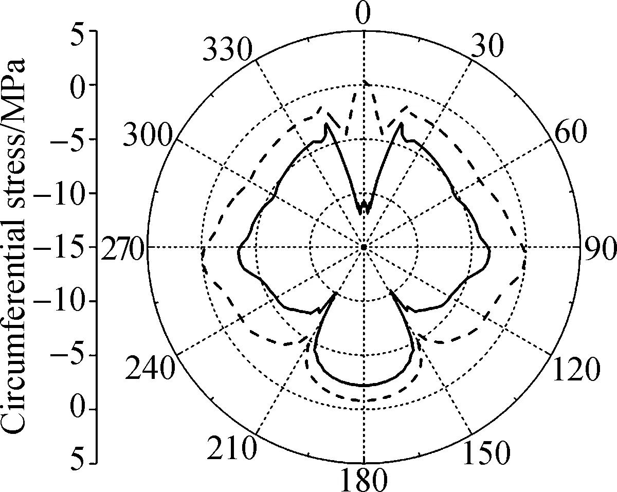
The distribution of circumferential stresses along the internal surface and external surface of the inner lining is shown in Fig.9 and Fig.10. Positive stress represents tensile stress and negative stress denotes compressive stress. Comparing the results of Fig.9 and Fig.10, we can find that deficiency in tunnel crown thickness has a considerable impact on the values and distributions of circumferential stresses of the inner lining.
According to Figs.9 (a) to (d), the values of circumferential stresses along the internal surface are less than the tensile and compressive strength of concrete C40. It can be concluded that deficiency in tunnel crown thickness will not lead to lining cracking at the internal surface in all of the four cases.
(a) (b) (c)
(d) (e) (f)
Fig.9Distribution of circumferential stresses along the internal surface of the inner lining. (a)T=0.45 m; (b)T=0.40 m; (c)T=0.325 m; (d)T=0.28 m; (e)T=0.22 m; (f)T=0.16 m

(a) (b) (c)
(d) (e) (f)
Fig.10Distribution of circumferential stresses along the external surface of the inner lining. (a)T=0.45 m; (b)T=0.40 m; (c)T=0.325 m; (d)T=0.28 m; (e)T=0.22 m; (f)T=0.16 m
In contrast, when the tunnel crown thickness is less than 0.28 m,the internal surface of the crown will become the compressive stress concentrated zone of the whole inner lining. As shown in Fig.9(e), the maximum compressive stress along the internal surface of the inner lining is -14.36 MPa under the CCT working condition. Compared withT=0.45 m, there is an evident increase of 143.4%. According to Fig.9(f), the maximum compressive stress along the internal surface of the inner lining is -24.53 MPa under the CCT working condition. Compared withT=0.45 m, there is an evident increase of 315.8%. It can be concluded that concrete at the crown may be crushed during the tensioning process if the tunnel crown thickness further decreases.
The results in Figs.9 (e) and (f) also show that partial areas of the inner lining’s internal surface are subjected to tensile stresses under the DWP working condition. The tensile areas are mainly located at the upper semicircle of the inner lining. At the same time, the tensile areas become larger, and the maximum tension stress will incrementally increase as the thickness of the tunnel crown further decreases gradually. As shown in Fig.9(e) and Fig.11(f), the maximum tension stress along the internal surface under the DWP working condition rises from 3.38 MPa forT=0.22 m to 10.31 MPa forT=0.16 m, with an evident increase of 205%.
According to Figs.10 (a) to (d), the values of circumferential stresses along the external surface range from 0.37 to -12.56 MPa in most areas of the inner lining. The external surface of inner lining can still maintain a satisfactory stress state in all of the four cases.
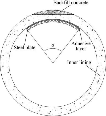
Fig.11 Reinforcement schematic of the inner lining
In contrast, when the tunnel crown thickness is less than 0.28 m,partial areas of the inner lining’s external surface will be subjected to tensile stresses under the DWP working condition. The tensile areas are mainly located at the tunnel crown. At the same time, the tensile areas become larger, and the maximum tension stress will incrementally increase as the thickness of the tunnel crown further decreases gradually. As shown in Fig.10(e), the maximum tension stress along the external surface under the DWP working condition rises from 0.37 MPa forT=0.28 m to 7.9 MPa forT=0.22 m, with an evident increase of 2 035.1%. As shown in Fig.10(f), the maximum tension stress along the external surface under the DWP working condition is 19.1 MPa. Compared withT=0.22 m, there is an evident increase of 141.8%. The tension stresses are 3 to 8 times the tensile strength of the inner lining concrete in these two cases.
3.3 Reinforcement schemes of the inner lining
According to Fig.9 and Fig.10, when the tunnel crown thickness is equal to or greater than 0.28 m, the tension stresses of the inner lining will not exceed the tensile strength of concrete C40. The stability and water-tightness of the inner lining can be ensured, and the inner lining can still operate normally. The reinforcement suggestions proposed for these cases are that the void spaces between the inner lining and the outer lining should be back-filled with concrete.
The above findings imply that the tension stresses of the inner lining will exceed the tensile strength of concrete C40 whenT=0.22, 0.16 m. In these cases, cracks at the inner lining may be expected. The tunnel cannot operate normally, and severe cracking, leaking or even failure may occur. After the concrete back-filling is carried out, the inner lining still needs additional reinforcement. As shown in Fig.11 and Tab.2, the reinforcement suggestions proposed for these cases are that the inner lining should be reinforced by bonded steel plate.

Tab.2 Reinforcement schemes
Finite element analyses are performed to reveal the strengthening effects of the proposed reinforcement schemes. To figure out the crack locations of the inner lining, the William-Warnke failure criterion is used to simulate the failure behavior of the inner lining concrete. The shear transfer coefficient for an open crack is defined as 0.5, and the shear transfer coefficient for a closed crack is defined as 0.9. The stress-strain relationship of steel plate in tension and compression is optimized to be bilinear kinematic hardening (BKIN) with a post-yield strain hardening of 1% (Esp=0.01Ese), whereEseandEspare the elastic and plastic modulus of the steel plate, respectively.
Fig.12 and Fig.13 show the crack locations (the blue zones) of the inner lining under the DWP working condi-tion. According to Figs.12 and 13, the crack scope of the reinforced cases is obviously smaller than the unreinforced cases. It can be concluded that the stick steel plate on the internal surface of the inner lining is an effective reinforcement method.
4 Conclusions
1) The inner lining can still maintain a satisfactory stress state when deficiency in the tunnel crown thickness exists, and undesirable stress levels may be caused only when the tunnel crown thickness decreases below 0.28 m.
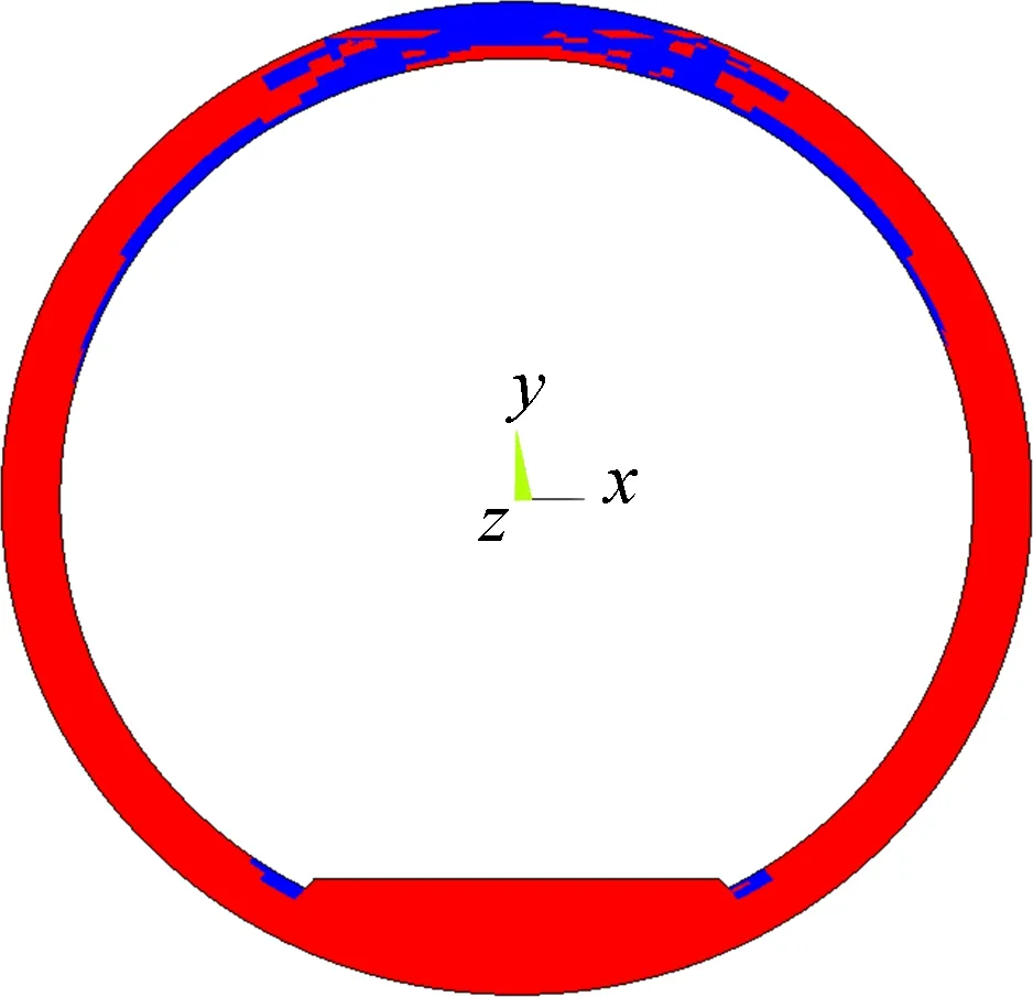
(a)(b)Fig.12 Crack locations of the inner lining forT=0.22 m. (a) Unreinforced case; (b) Reinforced case
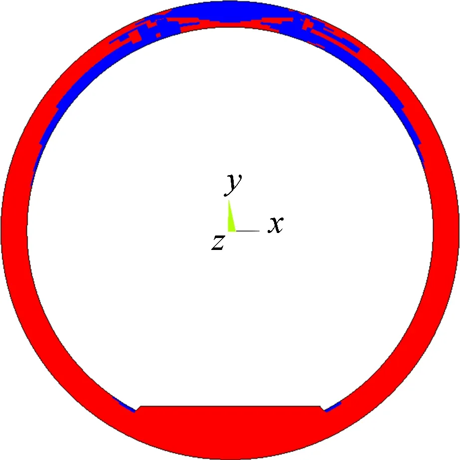
(a)(b)Fig.13 Crack locations of the inner lining forT=0.16 m. (a) Unreinforced case; (b) Reinforced case
2) Under the CCT working condition, the compressive stress concentration of the crown’s internal surface is very obvious. The compressive stresses will incrementally increase and ultimately exceed the compressive strength of the inner lining concrete as the crown thickness further decreases gradually. In other words, cracks may occur at the internal surface of the crown. Since the cracks form during the process of construction, they may be readily detected.
3) Under the DWP working condition, the external surface of the crown and internal surface of the crown’s adjacent areas will be under tension. The tension stresses will incrementally increase and ultimately exceed the tensile strength of the inner lining concrete as the crown thickness further decreases gradually. Then, cracks at the external surface of the crown and internal surface of the crown’s adjacent areas may be expected. Since the cracks form during the tunnel filled with upland water, they may not be readily detected until significant damage to the inner lining has been done, generally in the form of severe cracking, leaking or even failure.
4) When the tunnel crown thickness is equal to or greater than 0.28 m, the reinforcement suggestions are that the void spaces between the inner lining and the outer lining should be back-filled with concrete. When the tunnel crown thickness is less than 0.28 m, the inner lining should be reinforced by steel plates after concrete back-filling is carried out.
杂志排行
Journal of Southeast University(English Edition)的其它文章
- A recognition model of survival situations for survivable systems
- Big data assessment on the operating characteristics of on-line taxis and thoughts on relevant policies
- Experimental study of the onset of nucleate boiling in vertical helically-coiled tubes
- Syntheses and calculation of (E)-4-chloro-4’-ethoxystilbene and (E)-4,4’-dichlorostilbene
- A weighted selection combining schemefor cooperative spectrum prediction in cognitive radio networks
- Damage evolution analysis of cast steel GS-20Mn5V based on modified GTN model
