Nonlinear bending analysis of a 3D braided composite cylindrical panel subjected to transverse loads in thermal environments
2018-08-21YiXiZHAOTaoLIUZhiMinLI
Yi-Xi ZHAO,Tao LIU,Zhi-Min LI
Shanghai Key Laboratory of Digital Manufacture for Thin-Walled Structures,State Key Laboratory of Mechanical System and Vibration,School of Mechanical Engineering,Shanghai Jiao Tong University,Shanghai 200240,China
KEYWORDS
Abstract The aim of this study is to investigate nonlinear bending for a 3-Dimensional(3D)braided composite cylindrical panel which has transverse loads on its finite length.By refining a micro-macro-mechanical model,the 3D braided composite can be treated as a representative average cell system.The geometric structural properties of its components deeply depend on their positions in the section of the cylindrical panel.The embedded elastic medium of the panel can be described by a Pasternak elastic foundation.Via using the shell theory of the von Kármán-Donnell type of kinematic nonlinearity,governing equations can be established to get higher order shear deformation.The mixed Galerkin-perturbation method is applied to get the nonlinear bending behavior of the 3D braided cylindrical panel with a simply supported boundary condition.Based on the analysis of the braided composite cylindrical panel with variable initial stress,geometric parameter, fiber volume fraction,and elastic foundation,serial numerical illustrations are archived to represent the appropriate nonlinear bending responses.
1.Introduction
Composite materials are widely used to take place of metal structures in engineering for the aims of light weight and high resistance to chemical corrosion.The ability to design,analyze,optimize,and select proper materials for these structures is a necessity for structural designers,analysts,and researchers.It puts more and more important issues,like nonlinear mechanical behaviors of plate and panel structures,back on the front burner.Fabrication methods derived from the textile industry are used to manufacture textile composites for eliminating the delamination due to texture in-homogeneity.There are also numerous investigations into the physical and mechanical properties of composite plate structures,and minute analyses are available in the literature.1–4
Plates and panels are primary components in many structures including space vehicles,aircraft,automobiles,buildings,bridge decks,ships,and submarines.During the expansion of their usage,the physical characteristics of these composite plates/shells,like stability,bending,and vibration,attract much more interests of engineers.Large numbers of previous studies on the large deflection and/or nonlinear bending problem of thin plates are available.Reddy et al.5carried out bending analysis to study the effect of transverse shear deformation on deflections and stresses of laminated composite plates subjected to uniformly distributed load using the finite element method.Based on the first-order shear deformation theory,Xing and Xiang6studied linear buckling behavior of symmetric cross-ply rectangular composite laminates with a pair of parallel edges simply supported and the remaining two edges arbitrarily constrained.Brischetto et al.7investigated bending analysis of sandwich flat panels by applying the zig-zag function to the known higher-order theories.Considering the effect of transverse normal deformation of the core of a sandwich plate,Di Sciuva et al.proposed linear8and cubic9–11zig-zag theories that are able to compute transverse shear stresses directly from constitutive equations based on the cubic zigzag theory,which leads to piecewise parabolic shear stress vanishes on top and bottom surfaces,and in most cases,exhibits a good accuracy.Dawe and Wang12developed a spline finite strip method to predict the postbuckling response of composite laminated panels,with the nonlinearity introduced in enhanced strain–displacement equations for panels in a total Lagrange approach.On the other hand,analysis of structures and structural elements,supported on an elastic foundation,e.g.,soil,often requires the knowledge of the properties of the structures,as well as the properties of the soil.While properties of structural materials of a foundation and superstructure are usually well known,obtaining the soil’s properties and,especially,evaluating the soil’s behavior under applied loads,is very difficult.Various soils react differently to applied loads and,like any bearing material,produce under the same loads different settlements and different stresses.Analysis of beams,plates,panels,and other structures supported on elastic foundations is usually performed by modeling the soil;in other words,by replacing the soil with a material that behaves under applied loads like the given real soil.The most popular soil models used by practicing engineers are Winkler’s soil model or Winkler foundation proposed by Winkler13.Some scientists trying to improve the soil models mentioned above have recommended the use of new soil models.For example,Pasternak14proposed a soil model with two coefficients of subgrade reaction.The modulus of subgrade reaction represents a load that,being applied to one square unit of the soil surface,produces a settlement equal to one unit,and is the only parameter needed to obtain the settlement of the soil.The Winkler foundation is based on the following three assumptions:
(1)The load applied to the soil surface produces settlements of the soil only under the applied load and does not produce any settlements and stresses outside the loaded area.
(2)The soil can resist compression as well as tension stresses.
(3)The shape and size of the foundation do not affect the settlement of the soil.
These assumptions are not always accurate because it is well known that,in many cases,a load applied to the soil produces settlements not only under the applied load,but also outside the loaded area.
Based on a refined plate theory,Jiang et al.15studied the thermal bending behavior for a High-Strength Low-Alloy(HSLA)steel plate under a 3D temperature field,and the method of separation of variables16,17is used to provide geometrically nonlinear bending solutions for homogeneous isotropic and composite laminated plates subjected to mechanical and/or thermal loading and resting on an elastic foundation.In these studies,material properties were considered to be independent of temperature.Teo and Liew18presented a 3D analysis of rectangular orthotropic plates by employing the Differential Quadrature(DQ)method.They pointed out that the DQ method yields accurate results for the plate problems under investigation.Theoretical,numerical,and experimental studies which focus on the nonlinear problems involving bending,stability,and non-stationary vibrations are also addressed.It is noted that if the panels or plates in a structure are treated as 2D laminates,analyzed results will be some accidental non-linear distortions like inferior delamination resistance,redundant impact damage tolerance,and excessive notch sensitivity.In reality,in the case of the stress distribution analysis of a braided cylindrical plate/-panel with a moderate thickness,the loaded braiding cells play the major role due to the through-thickness-direction reinforcement.19,20However,it remains unclear whether 3D braided cylindrical panels still display a strong or weak nonlinearity under a low fiber volume fraction,and this motivates the current investigation.The present work focuses on the nonlinear bending response of a 3D braided composite cylindrical panel resting on an elastic foundation.A representative unit is established,which contains four interior cells and two surface cells in different regions by using a simple rule of mixtures idea.The algorithms are based upon Reddy’s higher-order shear deformation shell theory with a von Kármán type of kinematic nonlinearity.A mixed Galerkin-perturbation technique is employed to determine transverse load-deflection and load-bending moment curves with initial in-plane loadings.Numerical results are presented in a graphical form to illustrate the nonlinearity of the bending responses of 3D braided composite cylindrical panels resting on elastic foundations.
The paper is organized in the following manner.Section 2 is focused on the analytical material mathematical modeling,the displacement field,the elastic stress-strain relations,and the principle of virtual work.In Section 3,the analytical method and asymptotic solutions are presented.Section 4 presents numerical results and conclusions.
2.Theoretical development
Based on the carrier movement and using the method of material volume control and surface limitation,yarn traces can be analyzed to describe 3D tubular braided composite plate preforms systematically.Similar studies have also been reported by Wang Y.Q.and Wang A.2.
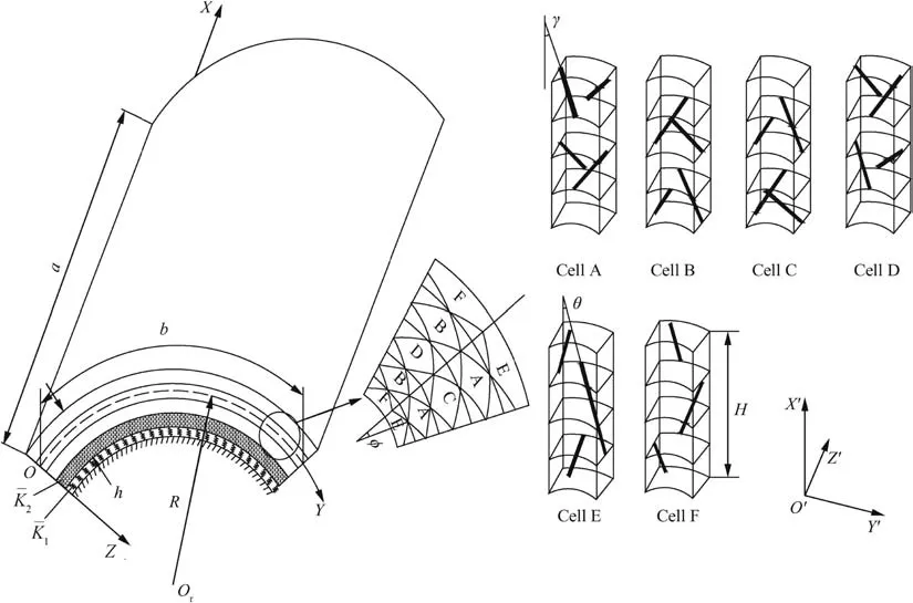
Fig.1 Configuration of a braided composite cylindrical panel as well as its coordinate system and unit cells for the interior(Cells A-D)and the surface(Cells E-F).
We developed a micro-macro-mechanical model,in which a macro-cell is further decomposed into simpler elements,called unit cells,as shown in Fig.1,in which¯K1and¯K2are the elastic stiffness of foundation.The stiffness of a unit cell is calculated from the geometry of the fiber tow and the stiffness of the constituents,and the yarn cross-section also changes into an elliptic shape due to the interaction between the yarns.The macroscopic stiffness between the unit cells can be qualitatively analyzed through load-sharing relations.According to the model,a 3D braided composite can be treated as a cell system.The profile of the cell is highly correspondent with the geometry position in the cross-section of the cylindrical panel.
For each unidirectional‘‘lamina”,the 3D stress/strain relationship under the global coordinate system(OXYZ)in 3D braided composite structures is given by(see Sun and Qiao21in detail)

In order to simplify the analysis,an assumption of the plane stress condition is made.Then,we have σZ= τYZ= τZX=0.Eq.(1)are simplified to

The coordinate system of a unit cell is defined as local coordinate system(O′X′Y′Z′).The braiding orientation is along the X′-direction,while the circumferential and thickness directions respectively correspond to the Y′-and Z′-direction.Because different mechanical properties of the fiber exist in the axial and the other two directions,we assume that the yarn( fiber tow)is transversely isotropic and the matrix is isotropic,and consider a linear elastic ‘‘lamina” with orthotropic material properties,so each system of yarn can be represented by a comparable unidirectional lamina(Shokrieh and Mazloomi 19).The elasticity matrix of each lamina in the material(yarn)coordinate system is determined by fiber properties,matrix properties,and the fiber volume fraction.Then,the elasticity matrix of the lamina in the unit cell coordinate system is determined by coordinate transformation.Finally,the elasticity matrix of a unit cell can be obtained by summing up individual elasticity matrices of all the laminae.The material principal directions are denoted by X′,Y′,and Z′in the local coordinate system.Therefore,the matrix can be expressed as

where Vfand Vmare the yarn and matrix volume fractions,respectively,which are related by

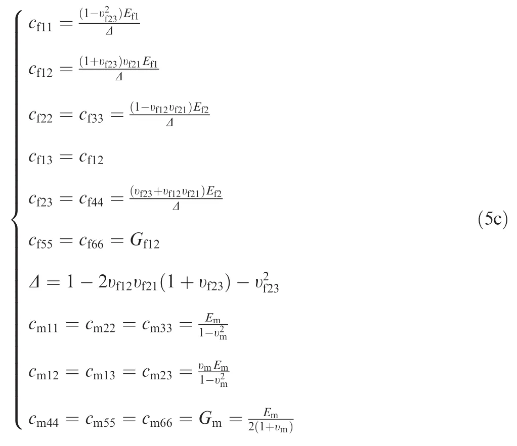
Cfand Cmare the elasticity matrices for the yarn and the matrix,respectively,which can be expressed as


in which
In Eq.(3),Tkis the transform matrix and can be expressed as
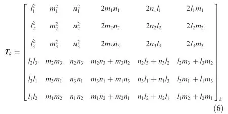
where li,mi,ni(i=1,2,3)are the direction cosines of a yarn with the surface braiding angle θ,interior braiding angle γ,and inclination angles χ,where χ is the angle between the projection of the yarn axis on the Y′O′Z′plane and the Y′-axis,while the braiding angle γ is the angle between the yarn axis and the X′-axis in Fig.1,which can be defined as
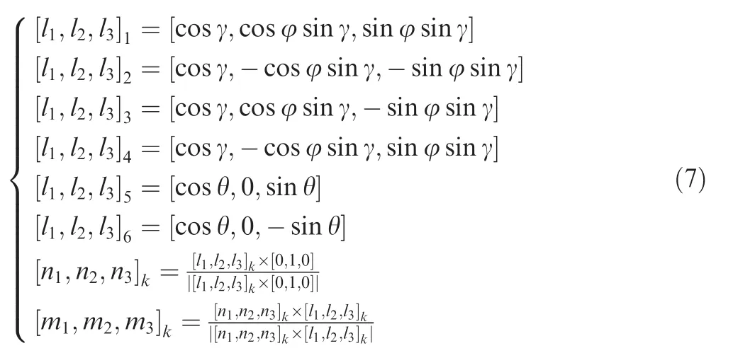
and

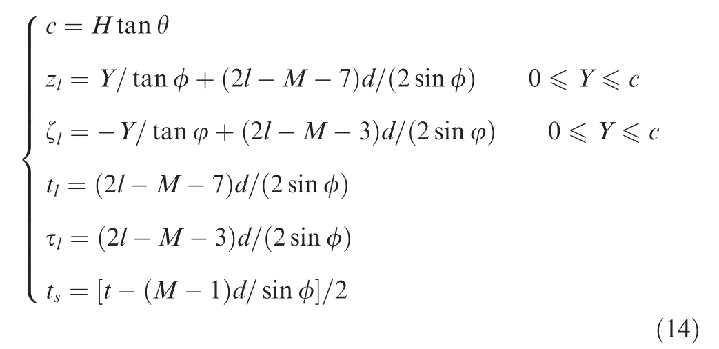
where φiis the oriental angle of the yarn cross-section in a specific layer,M and N are respectively referred to[M×N],representing the numbers of radical columns and circumference rows of the braiding carriers,Dinand Doutare the inside and outside diameters of the cylindrical panel,d indicates the short axis of the yarn cross-section,and the value of the pitch length H can be measured out from the exterior preform.The braiding angle and inclination angles vary between regions(inside and surface cells).A common theme in mechanical studies of braided fabrics and braided fabric reinforces composites is the relationship between the structural geometry of the braid and deformational characteristics.
In view of macro-mechanism,a shear deformable panel model is adopted.Consider a circular cylindrical panel with R being the radius of curvature,h the panel thickness,a the length in the X-direction,and b the length in the Y-direction,which is subjected to a transverse uniform load q=q0,a sinusoidal load q=q0sin(πX/a)sin(πY/b),or a concentrated load p(X=X0,Y=Y0)combined with thermal loading(show in Fig.2).The panel structure is placed into the system coordinate,in which directions X and Y are referred to the axial and circumferential directions while direction Z is the inward normal direction of the middle surface.The corresponding displacements are designated asandandare defined as the rotation angles of X-and Y-axes with the through-thickness direction of the panel.

Fig.2 Comparison between corresponding schematic diagrams for different loading conditions of a braided composite cylindrical panel.

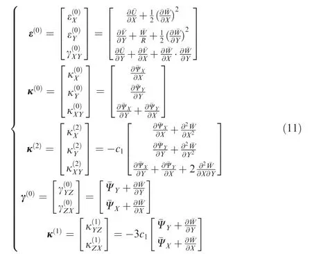
where c1=4/3h2,and as geometric non-linearity due to moderately large deflection and small rotations is considered in the analysis,the non-linear strains can be derived from the above displacement field and by using von-Kármán’s assumptions as follows:
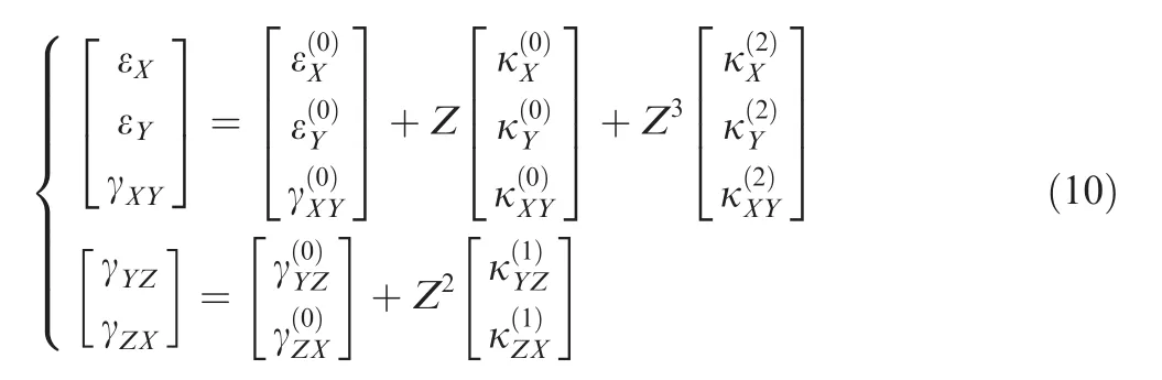
where
The outer panel surface which is in contact with an elastic medium acting as an elastic foundation can be represented by the Pasternak model.This foundation is customarily assumed by Paliwal et al.22to be compliant,which means that no cell can lift off in the large-amplitude vibration region.The load-displacement relationship of the foundation material is defined asin which p0presents the intensity,andas the Winkler and shearing layer stiffness of the foundation,respectively,and▽2refers to the Laplace operator in X or Y.The origin of the coordinate is located at the end of the panel.As in the high-order shell theory,the constitutive relations of the panel are
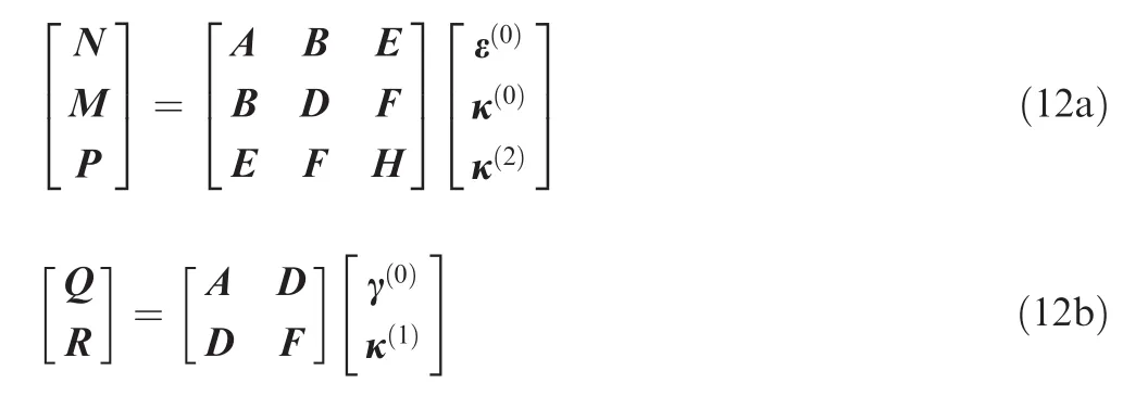
where N and Q are the membrane and transverse shear forces,M is the bending moment per unit length,and P and R are the higher-order bending moment and shear force,respectively.
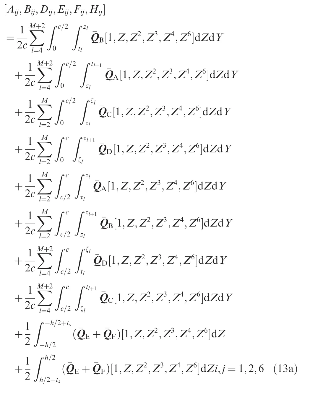
In reality,the unit cell of a panel braided structure has a curved geometry,and the radius of curvature of the unit cell is a function of the panel diameter.As the diameter of the panel braid decreases,the thicknesses of the strands deposited on the mandrel become uneven.The change in the curvature of the unit cell and the uneven strand thickness must be accounted for through geometrical characterization of the unit cell to obtain more accurate elastic property predictions.In order to produce thick structures,it is necessary to place multiple layers of cloth over the mandrel and the previous layer of fabric.A 3D braided structure is a thick knot which can take on various geometric configurations in an integrated manner.Thus the extension of braiding to 3D braiding resolves the laminate issue by producing a preform of suitable thickness which has no laminae.In practice,if the coordinate systems of unit cells and the plate structure do not overlap,coordinate transformation will be performed.The total volume of a repeating unit cell is expressed in the thickness and undulation terms.The total resin thickness in the repeating unit cell includes a local thickness for upper and lower resin layers,respectively.All these volumes are calculated using the same integration scheme as used in the subdomain zones and by considering the appropriate number of uniform yarn slices along the slices’centerlines that are uniform along the centerline arc-length.The laminate approximation of the unit cell structure gives the geometrical configuration and stacking sequence of the inclined laminae composed of yarns in four diagonal directions and inner and outer surfaces in two diagonal directions in the unit cell.The individual elasticity matrices of the ‘‘lamina” are summed up to get the matrix of the unit cell.The ‘‘lamina”elasticity matrices can be calculated by using two-direction integral involving the numbers of tracks and columns as follows:

The total stress resultants are defined by a semi-inverse relationship as Eq.(12)yields
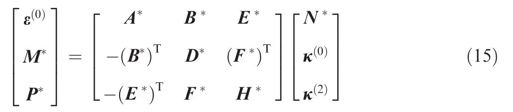
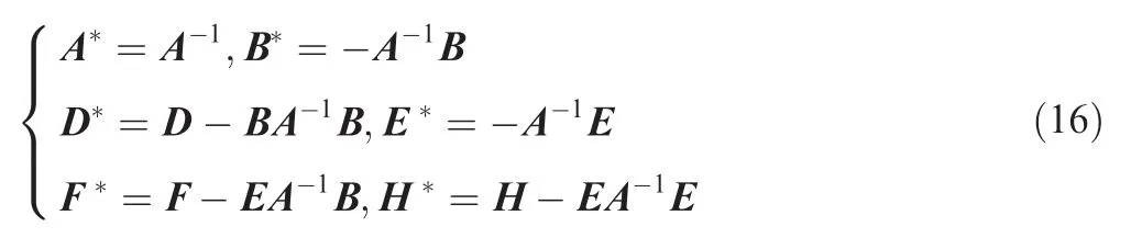
and

where Aij,Bij,Dij,Eij,Fij,Hij,are the laminate stiffnesses,see Eq.(13)in detail.
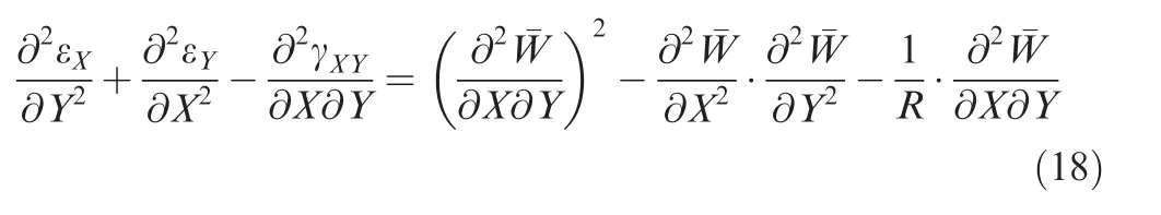
While the panel is assumed to be relatively thick,letY)present the additional deflection andbe the stress function for the stress resultants defined by,and,where the comma denotes partial differentiation with respect to the corresponding coordinates.Take the compatibility equation into account,that is,
On the basis of Sander’s shell theory,a simple higher-order shear shell deformation model was developed by Reddy et al.23–26,in which shell cells transverse shear strains are assumed as parabolic distributed and along the thickness direction.It contains the same dependent unknowns like the first-order shear deformation theory,but shear correction factors are not required.Reddy’s third-order plate theory to be developed is based on the same assumptions as those of classical and first-order plate theories,except that we relax the assumption on the straightness and normality of a transverse normal after deformation by expanding the displacements[U1,U2,U3]as cubic functions of the thickness coordinate.Many works have been published(see Ref.27),and we introduce Reddy’s third-order plate theory to investigate the nonlinear bending behaviors of 3D braided composite panels.By applying von Kármán-type kinematic relations into Reddy’s theory,the governing differential equations for 3D braided composite cylindrical shells are derived in terms of a stress functiontwo rotationsandand a transverse displacement¯W as follows:

Assume that the four panel edges under simply supported boundary conditions are with or without in-plane displacements,referred to as‘movable’and ‘immovable’in the following.When temperature rises steadily,the boundary conditions are

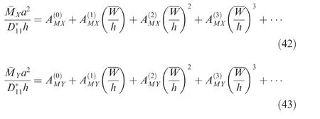
where σXis the average axial compressive stress,is the bending moment,andis the higher-order moment,as defined by Shen28.The in-plane boundary condition¯V=0(on X=0,a)is fulfilled on the average sense as

where superscript ‘‘T” represents the thermal-bending moments.
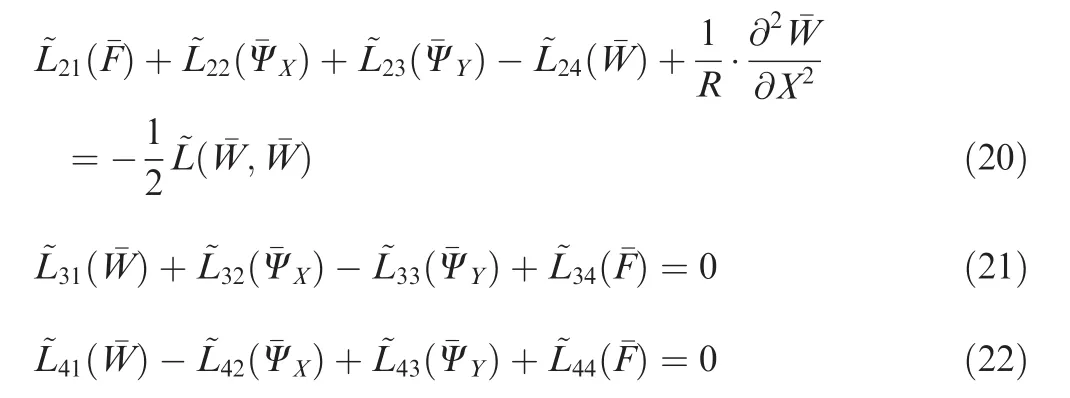
Eqs.(19)–(22)are the governing equations describing the required large deflection response of the moderately thick 3D braided composite cylindrical panel.
3.Analytical method and asymptotic solutions
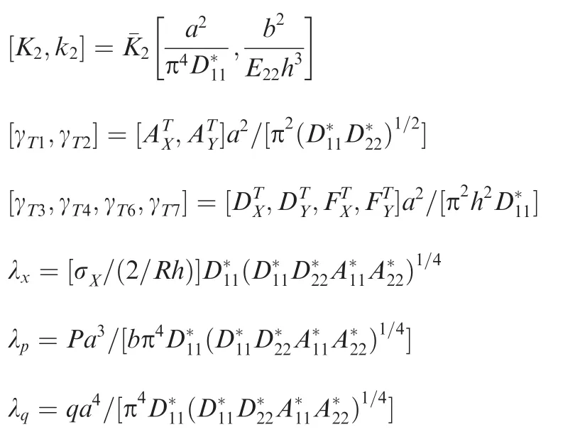
We are now in a position to solve Eqs.(19)–(22)with boundary conditions in Eq.(23).Before proceeding,it is convenient to firstly define the following dimensionless quantities with γijin Eqs.(25)–(28)below as shown in Appendix A.
The nonlinear Eqs.(19)–(22)may then be written in dimensionless forms as
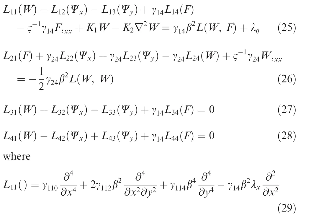
ς is dimensionless ratio of radius to length and the other dimensionless operators Lij()and L()are defined by Shen28.
The boundary conditions of Eqs.(23a)–(23h)become

The thermoelasticity bending response of a 3D braided panel under simply supported boundary conditions and transverse uniform or sinusoidal loading can be analyzed by the mixed Galerkin-perturbation technique via applying Eqs.(25)–(28).The essential assumptions are as follows:

in which ε is a small perturbation parameter,and the first term of wj(x,y)is supposed to have the form of

Then,we expand the equation of thermal-bending moments in the form of the double Fourier sine series,and can obtain the following relations:

Substituting Eq.(31)into Eqs.(25)–(28)and collecting the terms of the same order of ε,we can get a set of perturbation equations.Eqs.(30)and(31)can be used to solve these perturbation equations of each order.The amplitudes of the terms wj(x,y),fj(x,y), ψxj(x,y),and ψyj(x,y)are implicitly causal,and λjcan be obtained by applying the Galerkin procedure.The result up to third-order asymptotic solutions can be derived as
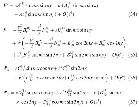
Note that for the movable edges boundary condition,it is just necessary to take(i=0,2)in Eq.(31),so that the asymptotic solutions have a similar form,and

All the coefficients in Eqs.(34)–(37)are related and can be written as functions ofso that Eqs.(34)and(38)can be rewritten as

and

From Eqs.(39)and(40),the load-central defection relationship can be written as
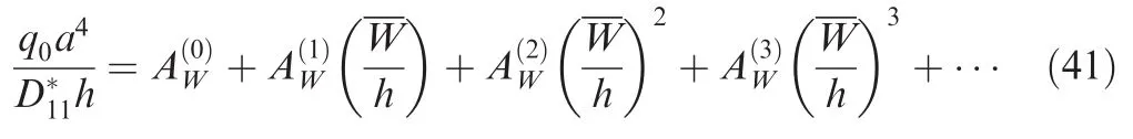
Similarly,the bending moment-central defection relationships can be written as
Eqs.(41)–(43)are employed to deduce the defection and bending moment of the 3D braided panel under the loading and boundary conditions in different thermal environments,and the mixed Galerkin-perturbation technique is adopted to resolve the load-bending moment and load-deflection curves.It is worthy to note that the governing differential Eqs.(19)–(22)for a 3D braided composite plate are identical in form to those of asymmetric cross-ply laminated plates.The major difference herein is that the plate stiffness is determined based on a micro-macro-mechanical model.
4.Numerical results and comment
To ensure the accuracy and effectiveness of the present model and method,the effective elastic constant E11and the fiber volume fraction Vffor ‘‘each lamina” along the radial position of graphite yarn 12 K fiber braided composite tubes(M×N=47×380)are compared and listed in Fig.3 with analytical results of Wang Y.Q.and Wang A.2.The material properties are Ef=234.4 GPa,υf=0.22 for carbon fiber,and Em=3.45 GPa,υm=0.34 for resin.The dimensions of these tube are R1×R2×h=60 mm×100 mm×40 mm.The crosssectional area of the braided yarn is 0.477 mm2,the pitch length H is 4 mm,and the short axis of the cross-section of the yarn d is 0.7 mm.It can be seen that the present results agree well with the analytical results of Wang Y.Q.and Wang A.2for 3D braided tubes.The comparison shows that the braiding angle gradually decreases from the inner surface to the outer surface,and the fiber volume fraction Vfalso decreases in a similar tendency in the same radical range.Furthermore,a comparison between the experimental data measured by Kalidindni and Abusafieh29and the theoretical predictions by Chen et al.30is listed in Table 1.The yarn and matrix properties adopted,as given in Ref.30,are:Ef1=234.6 GPa,Ef2=13.8 GPa,Gf12=13.8 GPa,υf12=0.22,Em=2.97 GPa,and Gm=1.11 GPa.It is seen from Table 1 that a good agreement between the predicted and experimental results is obtained.The results demonstrate that the mechanical properties of 3D braided composite tubes reflect the characteristics of their yarn structures.

Fig.3 Comparison of radical behaviors of predicted elastic constant E11 in tubular braids(M×N=47×380).
A parametric study has been carried out and typical results are shown in Figs.4–7.It should be appreciated that in all of these figures,¯W/h,¯Mxb2/E22h4,and q0b4/E22h4denote the dimensionless central deflection of the plate,central-bending moment,and lateral pressure,respectively.For all of the examples,the carbon fiber tows are used as a braiding material,and the material properties of graphite fiber and epoxy adopted,as given in Refs.31–35are:Ef1=233.13 GPa,Ef2=23.11 GPa,Gf12=8.97 GPa,Gf23=8.27 GPa, υf12=0.20, υf23=0.4,Em=(3.51–0.003ΔT)GPa, υm=0.34,and αm=45.0 ×10⁻⁶K-1,in which T=T0+ΔT and T0=300 K(room temperature),h=4.0 mm,a=b=40 h,and M×N=9×64.It is pointed out that because the thermal expansion coefficient of carbon fiber is relatively small,we only focus on the effect of the temperature rise of the epoxy based on the calculation.
Fig.4 illustrates the deflection and bending moment curves of panels with different values of the fiber volume fraction Vf(Vf=0.4,0.5,and 0.6)under a uniform pressure and thermal condition ΔT=0 K.The results show that the panel has raising deflection and decreasing bending moment while the fiber volume fraction becoming less.The comparison also implies that the highest static bending property of braided composites is achieved with a relatively high fiber volume fraction.
Fig.5 shows the effect of the initial stress on the nonlinear bending behaviors of 3D braided composite cylindrical panels under an axial tensile load λx=-0.5 λcrand a compressive load λx=0.5 λcr,where λcris the critical buckling load of the panels with a movable edge condition.It can be observed that these panels with initial compressive loads have higher deflections than those with initial tension loads and without initial loads.This is evidently due to the fact that the lateral displacement caused by one of the compressive loads helps the other loads to produce greater lateral displacements.
Fig.6 compares the load-deflection and load-bending moment curves of 3D braided composite cylindrical panels under three cases of transverse loading conditions(uniform,sinusoidal,and concentrated load P=1000 N,x0=0.5,andy0=0.5)along with environmental conditions ΔT=100 K.As it may be expected,the load-deflection curves of the braided panels subjected to a sinusoidal loading are lower than those of the panels subjected to a uniform loading.On the other hand,these results imply that a slender panel would have a bigger normal bending stress due to its weaker bending stiffness and larger deflections.

Table 1 Comparison between effective elastic constants E11 and G12 obtained from calculations and experiments.

Fig.4 Effects of fiber volume fraction on nonlinear bending behaviors of 3D braided composite cylindrical panels.

Fig.5 Effects of initial stress on nonlinear bending behaviors of 3D braided composite cylindrical panels with a movable edge condition.
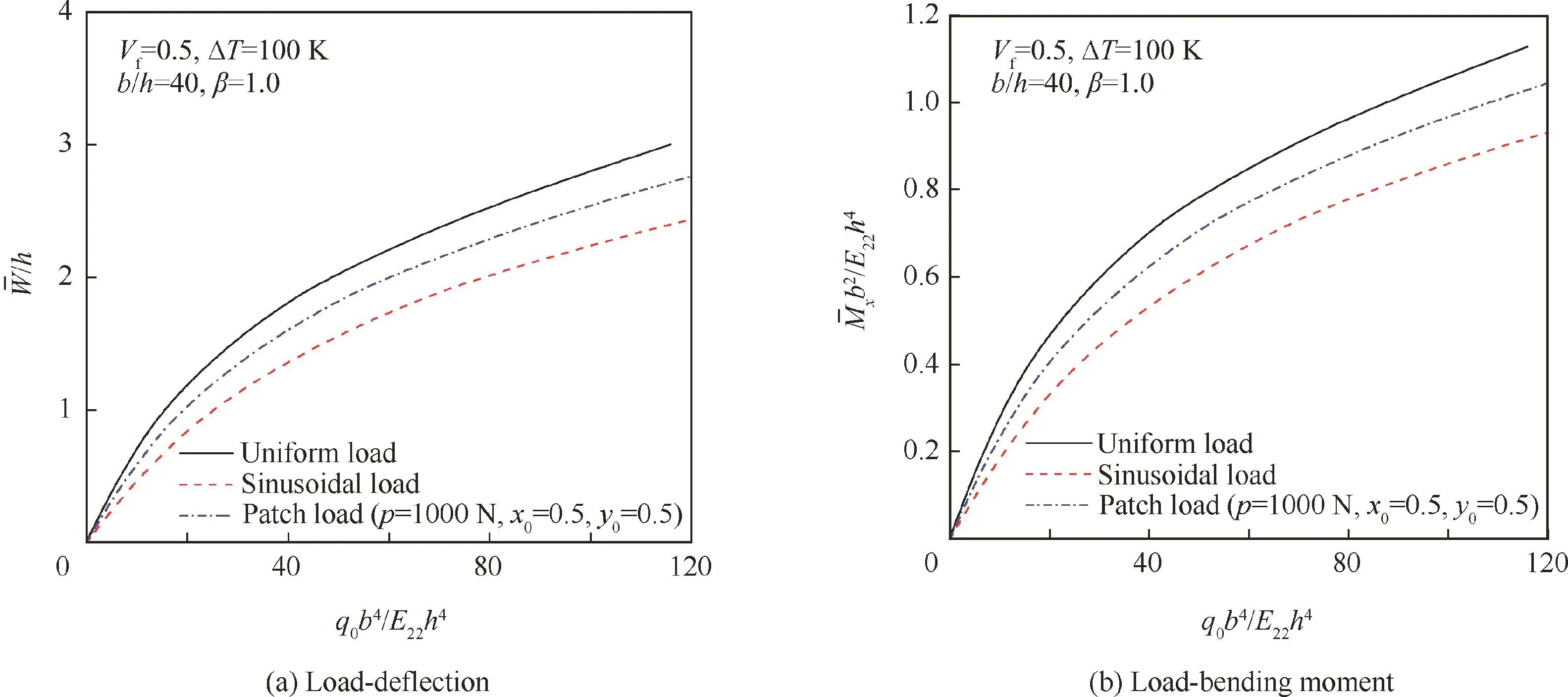
Fig.6 Effects of transverse loading on nonlinear bending behaviors of 3D braided composite cylindrical panels with an ‘immovable’end condition.
The effect of the elastic foundation stiffness on the nonlinear bending behaviors of 3D braided cylindrical panels with panel geometric parameters(a/b=1,b/R=1)and the fiber volume fraction (Vf=0.5) resting on two-parameter(Pasternak-or Vlasov-type)elastic foundations under two sets of edge conditions,i.e.,the immovable edges,is shown in Fig.7.Three sets of foundation stiffness are considered:(k1,k2)=(100,10)for the Pasternak elastic foundation,(k1,k2)=(100,0)for the Winkler elastic foundation,and(k1,k2)=(0,0)for the panel without an elastic foundation.As expected,the bending stiffness of 3D braided panels increases as the foundation stiffness increases.It is evident that increases of these stiffness coefficients lead to a decrease of the bending deflection.This is attributed to the increase of the stiffness contributed by the elastic foundation.However,numerous experimental and theoretical investigations proved that analysis based on a Winkler foundation produces realistic results that are practically close enough to results obtained from soil testing and observations of settlements of real structures.Tension stresses between the soil and foundation occur in some cases,not only when Winkler’s soil model is used.They occur regardless of what kind of soil model is used.In addition,it is important to remember that in most of the cases,the weight of the structure is very high,and tension stresses practically do not take place.
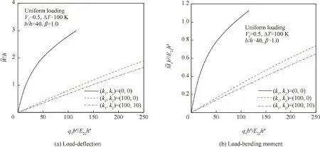
Fig.7 Effect of elastic foundation on nonlinear bending behaviors of 3D braided composite cylindrical panels resting on elastic foundations.
To investigate the significance of 3D braided composite cylindrical panels on the nonlinear bending responses of 3D braided composite panels with different fiber volume fractions,geometric properties of panels,edge boundary conditions,and elastic foundations are plotted in Figs.4–7.It can be seen from these figures that the fiber volume fraction,initial stress,geometric properties of panels,edge conditions,and elastic foundation parameters are all crucial components factors in determining the nonlinear bending responses of 3D braided composite panels.In addition,a fabric geometric model has been developed to characterize the 3D braided preform composite with regard to the yarn and the matrix,and processing parameters.The 3D braided unit cell geometry in the micromacro-mechanical model requires two basic components:fabric geometry and determination of the fiber volume fraction.However,the yarn structure and the properties in the final product can differ widely.It is possible that an optimal preform design may be found to meet most if not all of the preset property requirements through selections of the M,N,H,and d combinations based on the present micro-macro-mechanical model.It is hoped that the results presented will contribute to a better understanding of the nonlinear bending behaviors of 3D braided panels with four free edges subjected to thermomechanical loads and resting on tensionless elastic foundations.
5.Conclusions
Reinforced,braided panels are seeing an increased use in structural applications where light-weight and high loadcarrying capacities are critical.However,research on the structural behaviors of these panels has been limited.In this paper,a numerical calculation method is introduced which is focused on the analysis of the nonlinear systematical behavior of a 3D braided composite cylindrical panel structure.A parallel shell-type cell structure is proposed as the micromacro-mechanical model for the bending behavior analysis.The corresponding deformation analysis is presented based on the related elasticity shell theory.By applying the double Fourier series as the displacement mode and the Galerkin procedure,the exact solution of the nonlinear bending responses of a 3D braided composite cylindrical panel with simply supported boundary conditions under transverse uniform or sinusoidal loading is obtained.The major influent factors are also listed and analyzed,such as the panel geometric parameter, fiber volume fraction,load pressure,and thermal environment.Results reveal that the fiber volume fraction,initial loading,foundation stiffness,and the geometric parameter of the panel have significant effects on its nonlinear bending responses.
Acknowledgements
The work described in this paper was supported in part by grants from the National Natural Science Foundation of China(Nos.51375308 and 51775346).The authors are grateful for these financial supports.
Appendix A

杂志排行

CHINESE JOURNAL OF AERONAUTICS的其它文章
- Ion engine grids:Function,main parameters,issues,configurations,geometries,materials and fabrication methods
- Aeroelastic stability analysis of heated flexible panel subjected to an oblique shock
- Damage localization eあects of the regenerativelycooled thrust chamber wall in LOX/methane rocket engines
- Receptivity and structural sensitivity study of the wide vaneless diあuser flow with adjoint method
- Large-eddy simulation and linear acoustic modeling of entropy mode oscillations in a model combustor with coolant injection
- Development of secondary flow field under rotating condition in a straight channel with square cross-section