Ion engine grids:Function,main parameters,issues,configurations,geometries,materials and fabrication methods
2018-08-21MiguelSANGREGORIOKnXIENingfeiWANGNingGUOZunZHANG
Miguel SANGREGORIO ,Kn XIE ,*,Ningfei WANG ,Ning GUO ,Zun ZHANG
a School of Aerospace Engineering,Beijing Institute of Technology,Beijing 100081,China
b National Key Laboratory of Science and Technology of Vacuum Technology and Physics,Lanzhou 730000,China
KEYWORDS
Abstract Ion optics are crucial components of ion thrusters and the study of the different ion extraction solutions used since the beginning of the electric propulsion era is essential to understand the evolution of ion engines.This work describes ion engine grids’main functions,parameters and issues related to thermal expansion and sputter erosion,and then introduces a review of ion optics used for significant launched and tested ion thrusters since 1970.Configurations,geometries,materials and fabrication methods are analyzed to understand when typical ion thrusters use two or three grids,what are the thicknesses and aperture sizes of the screen,accelerator and decelerator grids,why molybdenum and carbon-based materials such as pyrolytic graphite and carbon–carbon are the best available options for ion optics and what is the manufacturing method for each material.
1.Introduction
The ion thruster,or Gridded Ion Engine(GIE),is a mature electric propulsion technology whose development started in the 1960s1–4and has since then been used for commercial satellite propulsion(Boeing 702,Boeing 601HP,etc.)and scientific missions(Deep Space 1,Dawn,etc.).1–5Ion propulsion with GIE is a rapidly evolving research field where new directions,such as new propellants,6–8and new concepts,such as the annular ion engine,9–12are currently under development.
The ion thruster’s main feature is that the propellant ionization process and the ion acceleration process are physically separated,contrary to other electric thrusters such as hall thrusters.1,2The ionization process takes place in the discharge chamber of the thruster and can be achieved by different principles,13namely electron bombardment(Kaufman thruster),14–16Radio Frequency waves(RF thruster)17–19or Electron Cyclotron Resonance(ECR thruster).20–22Regardless of the thruster type,the ion acceleration process consists of the extraction of ions from the discharge chamber by means of a multi-aperture grid assembly called ion optics or ion engine grids.23
Ion optics play a key role in ion thruster performance,and their erosion is the main life-limiting mechanism of the engine.1Since the beginning of the electric propulsion era,many efforts have been made to improve ion engine grids to increase the service life of the thruster.Alongside the plasma generator and the neutralizer,ion engine grids are the components that decide the GIE’s geometry,1so their study is essential for the scaling of the engine.This work contains an extensive literature review of the available information about ion optics of different sizes,shapes and materials developed by space agencies and companies for significant ion thrusters.
This paper is organized as follows.A brief description of ion engine grids’functions and main parameters is introduced in Section 2.Section 3 summarizes the main challenges faced by ion optics during their service life,focusing on thermal expansion problems and sputter erosion.Section 4 reviews the ion optics used for significant launched and tested ion thrusters from the 1970s to date.Section 5 analyzes the different configurations for ion extraction systems and their potential profile,while Section 6 focuses on the apertures’geometry,optics’thickness and grid-to-grid gap.Section 7 deals with the different candidate materials for ion engine grids and Section 8 describes the fabrication methods used to manufacture ion optics of different shapes and materials.Finally,Section 9 presents conclusions about general features that are common to ion engine grids.
2.Ion optics function and main parameters
Ion thrusters are characterized by the electrostatic acceleration of ions extracted from a plasma source.24The ion accelerator consists of electrically biased multi-aperture grids,typically two or three,which are called ion optics.The grid in contact with the plasma in the discharge chamber is called screen grid,the second one is called accelerator(accel)grid,and the third one,used in some engines,is called decelerator(decel)grid.The thruster ion optics assembly serves three main purposes1:(A)extract ions from the discharge chamber,(B)accelerate ions to generate thrust and(C)prevent the backstreaming of the electrons from the neutralizer hollow cathode.Fig.1 shows the main parts of a Kaufman type ion thruster with a two-grid extraction system.

Fig.1 Kaufman type ion thruster components.
Ion optics are characterized by a series of geometric parameters and electrical parameters(see Fig.2):grid outer diameter(D),similar to the discharge chamber diameter,grid active diameter or beam diameter(Dac),screen grid thickness(ts),accel grid thickness(ta),decel grid thickness(td),screen grid aperture diameter(ds),accel grid aperture diameter(da),decel grid aperture diameter(dd),screen-accel gap(lsa),accel-decel gap(lad),screen grid potential(Vs),accel grid potential(Va)and decel grid potential(Vd).
The acceleration length(le)is defined as
For a given grid,open area fraction is the ratio of the aperture array surface(combined area of the holes)to the grid surface and grid transparency(T)is defined as the ratio of the beam current that passes through the grid(Ib)to the total ion current that reaches the grid(Ii):
Sections 4–6 focus on the geometric parameters(D,ts,ta,td,ds,da,dd,lsa,lad)of significant ion engine grids and Section 5 refers to the electrical parameters(Vs,Va,Vd).
There are also some parameters that can be used to assess the quality of the grids,that is,how well they can accomplish their functions:
The Normalized Perveance per Hole(NPH)is the amount of current that a single aperture can extract and focus.It is defined as25,26
where Jbis the beam current per hole and Vtis the total voltage applied between the accel and screen grids:

NPH measures the extraction capability of a given aperture.For the NSTAR ion thruster,3NPH decreased with the discharge-to-total voltage ratio(discharge voltage is the discharge cathode potential)from 2.1×10⁻⁹A/V1.5to 1.2×10⁻⁹A/V1.5.
Beam divergence is how much the plasma beam expands after it has been focused(see Fig.3)and can be characterized by the divergence angle(α)which is defined as5

Fig.2 Ion optics parameters.
Fig.3 Plasma beam divergence angle and beam current density profile.

where Rαis the radius normal to the beam axis of the cone that encloses 95%of the total beam current,rαis the ion beam radius at the thruster exit and L is the distance from the thruster exit to the region where Rαis measured(see Fig.3).The divergence angle can also be defined for a beamlet focused by a single aperture.
Beam divergence should be minimized to reduce thrust losses and avoid plume impact on the spacecraft.1For two grid acceleration systems,different experiments yielded divergence angle values between 10°and 25°approximately.27
As shown in Fig.3,the beam current density profile can be obtained by a set of Faraday probes.Achieving uniform beam profiles contributes to decreasing localized erosion,and can therefore increase the lifetime of the grids.The nonuniformity of the current density profile can be described by the beam flatness parameter(fb),which is defined as the ratio of average-tomaximum beam current density28,29:

As stated in Section 1,the propellant ionization and ion extraction processes are physically separated in GIE.However,different ionization methods(electron bombardment,radio frequency waves or electron cyclotron resonance)will produce slightly different ion densities and temperature distributions,so ion optics’main parameters will have to be adjusted accordingly in order to provide an efficient extraction and acceleration of the ions.
3.Main issues of ion optics
Ion optics problems can be divided into three categories:launch problems,operation issues and sputter erosion.
Potential launch problems relate to launch vibrations,31–33which can generate plastic deformation,grid-to-grid contact and aperture misalignment.Displacement of the accel grid aperture relative to the screen grid centerline causes an off axis deflection of the ion trajectories,commonly called beam steering.1In order to prevent these issues,ion optics are subjected to random vibration tests at protoflight levels in three axes,31both isolated and mounted on the thruster,to validate the design and prove that vibration-induced stresses will not exceed the elastic limit stress and that grid gap and holes’alignment will not be altered.
Ion thruster optics are operated at high voltages and elevated temperatures,which leads to thermal response,electrostatic pressure,and interference with the discharge chamber magnetic circuit.Although electrostatic pressure is not a real problem(for a potential difference of 1500 V,which is a worst-case condition,0.254 mm grid-to-grid separation,electrostatic pressure was determined to be 152 Pa)34and the magnetic interference is solved by building the grids with diamagnetic or weakly paramagnetic materials(metals such as molybdenum and titanium and carbon based material),grids thermal expansion can generate problems,especially in thrusters that utilize refractory metal optics.
For a 30 cm thruster operating at a 350 W discharge power,temperatures at the centers of the screen and accel grids are of the order of 350 °C and 290 °C,respectively,with a 60 °C temperature difference.During the start-up phase,this difference increases up to 130°C.35Temperature difference induces thermal expansion that changes size of the acceleration gap between the screen and accel grids,which will directly affect the ion trajectories and the perveance of the ion optics.Additionally,thermal expansion results in buckling and plastic deformation,which prevents proper thruster operation.
A critical failure mode is the sputter erosion of the grid surfaces.36It occurs very slowly,taking several tens of thousands of hours before it can cause ion thruster malfunction.37There are five failure modes related to sputter erosion38:(A)accelerator grid structural failure from charge-exchange ion sputter erosion of the downstream accelerator surface;(B)electron backstreaming due to enlargement of the accel grid apertures from charge-exchange ion sputter erosion;(C)a grid electrical short that cannot be eliminated by the grid clearing circuit;(D)screen grid sputter erosion by discharge chamber ions;(E)accelerator grid structural failure due to direct ion impingement from defocused beamlets as a result of foreign material on a screen grid aperture.Among them,the first and second modes,the most damaging ones,have been subject to more intensive study.
After many wear tests,ion thruster testing revealed that engine failure occurs because material is eroded from the accel grid to the point where it fails structurally.39–42This type of failure occurs as a result of ions produced at or downstream of the grids in the ion beam which move upstream(counter to the higher velocity beam ions).These ions strike the accel grid and erode it through the sputter erosion process.
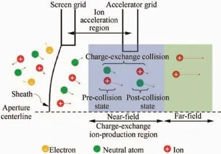
Fig.4 Charge-exchange collision.
Fig.4 shows a sketch of a single screen/accel grid aperture pair along the centerline of these apertures.The electrons(yellow),ions(red),and neutral atoms(green)to the left of the sheath(i.e.in the discharge chamber)are each moving at their respective thermal speeds when they are far from the sheath.As they migrate through the sheath,they transform from a plasma at a uniform potential within the discharge chamber into a region of steep electrical potential gradient created by the screen and accel grids.At the sheath,ions begin their downstream acceleration and the electrons are reflected back into the discharge chamber.Neutral propellant atoms,having no net charge,also pass downstream through the sheath,but they are unaffected by the potential gradient there.Ions move through the ion acceleration region and gain kinetic energy(longer velocity vectors),generally without interacting with the neutral propellant atoms which are just drifting through this region.These two particle species,however,occasionally undergo a charge-exchange collision(center of Fig.4).A charge-exchange collision involves the transfer of an electron from the slow-moving neutral propellant atom to the fastmoving beam ion.This transfer results in a charge-exchange ion with the low energy of the pre-collision neutral atom and an atom with the high energy of the pre-collision beam ion.Both beam and near- field charge-exchange ions reach their maximum kinetic energies near the accel grid and then undergo a slight deceleration as they exit the ion acceleration region.Beam ions have sufficient kinetic energy to escape this potential deceleration well,while the lower energy near- field charge-exchange ions typically do not.Therefore,all the charge-exchange ions created within the near- field charge exchange ion-production region will impinge on the accel grid and cause sputter erosion.40As beam ions and neutral particles proceed into the downstream(far- field)region,it is possible for further charge-exchange collisions to occur,but the probability that the charge-exchange ions created in the far field region impinge upon the accel grid is much lower.43
Although sputter erosion is typically non-uniform over the downstream surface of the accel grid,erosion around an aperture surrounded by other six holes consists of pits which develop among three adjacent apertures and trenches or grooves that join every pair of pits.1Fig.5 shows the idealized hexagonal erosion patterns and a simulation of the aperture enlargement.37When pits and trenches progress and reach the hole contour,they cause aperture enlargement,which will result in electron backstreaming.
Eventually the accelerator grid apertures become too large to prevent electron backstreaming or enough material is sputtered away that the grids fail structurally.Alongside grids’thermal expansion,which can decrease thruster’s performance,sputter erosion is the most life-limiting problem of ion engine grids.

Fig.5 Idealized grid erosion pattern and simulated aperture enlargement.37
Ion optics design is a trade between performance and life,the grids must extract the ions from the plasma source and accelerate to generate thrust and at the same time sputter erosion and thermal expansion problems have to be addressed to guarantee a long life for the extraction system.The next sections review the solutions in configuration,materials and fabrication adopted for several significant thrusters with different applications.
4.Ion optics of significant thrusters
Since their flight tests in the 1960s,ion thrusters have played important roles in the propulsion of many spacecraft.Ion optics,as crucial component of the engines,have evolved in many aspects with the goal of increasing thruster’s service life.Although specific information about ion optics is usually restricted,details about materials,shapes and sizes of the extraction systems used for some meaningful research projects and missions can be found in the literatures44–79(Table 1).Ion optics major dimension refers to the Dacof the circular grids and to the diagonal of the rectangular grids.For ion optics using two materials,the color represents the material of the screen grid;for those whose screen grid material is not reported,the color represents the material of the accel grid.
Fig.6 shows two timelines with the grids installed in some famous launched and tested ion thrusters from 1970 to date.44–79Dates for the testing of the grids,if not specified in the literature,are taken as the earliest found data publication year.
After the failure of SERT I in 1964,SERT II,which carried molybdenum ion optics was successfully launched and tested in space in 1970.44,45Twenty-two years later,in 1992,the European Space Agency’s(ESA)scientific mission EURECA tested RIT-10 in space,which was launched again in 2001 as the propulsion system of ARTEMIS,using a graphite accel grid.46,47In 1997,XIPS 13,with a three-grid extraction system,was incorporated in the Boeing 601HP communication satellite to provide NSSK(North-South Station Keeping),momentum dumping and eccentricity control;in 2007,60 of these engines were operating in space.A bigger version of the XIPS 13,the XIPS 25,with three dished molybdenum grids,was included in the Boeing 702 communication satellite and launched for the first time in 1999.50–52In 1998,the National Aeronautics and Space Administration’s(NASA)NSTAR,the biggest thruster at that moment,successfully propelled the Deep Space 1 mission and demonstrated the viability of ion propulsion for deep space applications.An improved NSTAR version was included as the propulsion system for the Dawn mission in 2007.Both NSTAR carried 30 cm dished molybdenum grids.53–56In 2003,the Japan Aerospace Exploration Agency(JAXA)successfully used the μ10 thruster,witha full Carbon–Carbon(CC)extraction system,for the Hayabusa mission.64,65In 2009,the GOCE mission used the T5 Kaufmann type thruster for drag compensation,and in 2018,a bigger thruster of the same family,the T6,is planned to be included in the BepiColombo mission to Mercury.These thrusters use two inward-dished grids of different materials for their extraction systems.69,70,78,79In 2012,China’s satellite SJ-9A carried the LIPS 200 ion thruster with a two-grid extraction system.74–77

Table 1 Grids used in some significant launched and tested ion thrusters.
In 1995,ESA-XX ion thruster was tested using three inward-dished molybdenum grids.48,49RIT-EVO and RITXT were developed after the RIT-10 engine with larger grids,respectively,and tested between the end of the 1990s and the beginning of the 2000s.47,57,58In 2002 were published the performance results of the NEXT ion engine optics,two molybdenum grids based on the NSTAR extraction system.59–61NEXT thruster underwent a long-duration test from 2005 to 2014,80among which goals was to measure the wear rates of the optics.In 2003,NASA tested a large ion thruster with rectangular optics and made of Pyrolytic Graphite(PG),the HiPEP,62,63the second biggest ion engine after NEXIS,whose big CC grids’manufacturing,wear tests and vibration tests’results appeared in 2005.31,66–68In 2011,the proof-of-concept PEGASES thruster,which generates thrust by accelerating both positive and negative ions from the same source,was conducted using two rectangular stainless steel grids.71–73
Fig.7(a)–(c)show,respectively,the relation between ion optics’size,material,shape,power,thrust and specific impulse of the ion engines in which they were installed(maximum values,as reported in the references.44–79,81).
The time lines in Fig.6 and the graphics of Fig.7(a)-(c)show that,among the studied thrusters,Mo was the preferred material for ion optics of all sizes and ranges of power,thrust and specific impulse Ispuntil the 2000s,when thrusters with higher power,thrust and Ispstarted to use carbon based materials for NEXIS and HiPEP engines.
5.Extraction system configurations and potential profile
Typical extraction systems use two-grid or three-grid configurations.For three-grid accelerator systems,a final grid called‘‘decel grid” is placed downstream of accel grid.This grid shields the accel grid from ion bombardment by charge exchanged ions produced in the beam from back flowing toward the thruster,and mitigates the downstream ‘‘pits and-grooves erosion”.Three-grid systems then potentially have longer accel grid life than two-grid systems and generate less sputtered material into the plume that can deposit on the spacecraft.
While smaller thrusters(SERT II,RIT-10,μ10,etc.,with diameters equal to or smaller than 15 cm)typically use flat ion optics,bigger grids(NSTAR,NEXIS,NEXT,LIPS 200,etc.,with diameters bigger than 15 cm)are normally dished to provide structural rigidity to survive launch loads and to ensure that they expand uniformly together during thermal loading.Thermal expansion of the grids during thruster operation changing the acceleration gap dimension between the screen and accel grids is a significant issue in ion thrusters,especially in those that use refractory metal grids.This will directly affect the ion trajectories and the perveance of the ion optics.The way in which thermal expansion will influence ion trajectories and perveance can be decided through the shape of the grids.
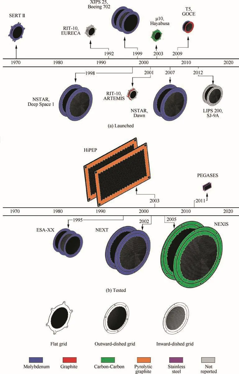
Fig.6 Grids used in some significant launched and tested ion thrusters(dates as in Table 1).44–79
Screen grid is heated by direct contact with the discharge plasma and its expansion is usually larger than the accel grid’s.If the optics are dished outwards,the acceleration gap tends to decrease as the thruster heats up,which causes the perveance of the optics to increase and changes the beamlet trajectories.For grids domed into the thruster(inward-dished),the screen grid expands away from the accel grid and the perveance decreases as the gap gets larger.1
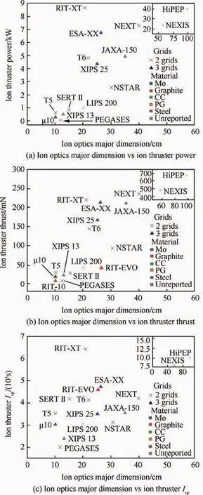
Fig.7 Ion optics major dimension vs ion thruster magnitudes.44–79,81

Table 2 Number and shape of grids used for some significant thrusters.
Table 2 shows the number and shape of grids used for some significant thrusters.Among smaller extraction systems(diameter smaller than 15 cm),the most common configuration is three flat grids(RIT-10,μ10),while most bigger thrusters(diameter bigger than 15 cm)use two outward-dished grids(NSTAR,NEXIS,NEXT,LIPS 200).For smaller thrusters,where temperature differences between the center and the edge of the grids are not as noticeable as for bigger optics,a flat solution provides enough structural integrity;besides,given that the fabrication and installation of a flat decel grid do not significantly increase the complexity of the extraction system,it can be included to shield accel grid.Dished grids are preferred for large area ion optics,as this shape significantly reduces the stresses that can cause the buckling of the structure,especially during launch,and provides better control of the thermal expansion process,guaranteeing that the grids will expand in the same direction.82Table 2 only includes information about circular ion optics.The facts that HiPEP and PEGASES use a rectangular shape instead of a circular one seem to be a design choice,as no explanation about the advantages of this shape has been found in the available literature.
Fig.8 shows the potential profile of the ion acceleration system.Screen grid is connected to a positive high-voltage supply to provide some confinement of the electrons in the plasma so that ions that strike it have a relatively low energy and cause little sputtering.Accel grid is negatively biased to create a potential barrier to stop neutralizer electrons,much more mobile than ions,from flowing back into the discharge chamber.Decel grid,when included,has zero electric potential.
Fig.9 shows the variations of the screen and accel electric potential during a test of the NSTAR thruster at different throttle levels(TH):for screen grid,the voltage grows from 650 V at TH1 to 1100 V at TH3 and then stays constant to TH16;for accel grid,the electric potential is-150 V from TH1 to TH7,and then is decreased to-180 V from TH8 to TH16.It can be seen that,for operational points from TH3,the total acceleration potential is around 1300 V.83,84

Fig.8 Potential profile of ion acceleration system.

Fig.9 Potential variation of NSTAR ion acceleration system for different throttle levels.83
6.Grids’thickness,apertures and gaps
Basic ion extraction systems usually follow the same pattern:screen grid is designed with a minimum thickness to increase the effective transparency and accel grid tends to be thicker for better erosion resistance.Decel grid,when included,is normally thinner than screen grid.
Fig.10 shows the thicknesses of the grids used in several thrusters.44–81Screen grid is thicker than accel grid for most of them(NEXIS,SERT,NSTAR,RIT-XT,RIT-EVO,ESA-XX),although in some cases these two grids have the same thickness(RIT-10, μ10).Decel grid,except for μ10,which has three grids of the same thickness,is thinner than screen grid(RIT-10,RIT-EVO,ESA-XX).
Ion optics apertures are typically circular,and packed in a hexagonal array to produce a high transparency to the ions from the plasma source(other patterns have been mentioned in a few simulation researches,85,86but not implemented).To accelerate ions to high energy,it is necessary to reduce the dimension of an aperture at the plasma boundary to the order of the Child–Langmuir distance to establish a sheath that will accelerate the ions with good focusing and reflect the electrons from the plasma.For Xenon,the characteristic aperture dimension of the screen grid is on the order of 2–5 mm,and the diameter of each accel grid aperture is minimized to retain unionized neutral gas in the plasma generator.1Decel grid’s apertures are usually larger than accel grid’s holes,and can have smaller,the same or larger sizes compared with screen grid’s apertures.
Fig.11 shows the aperture diameters of the screen,accel and decel grids of some relevant thrusters.44–81Except for the experimental PEGASES,all screen grids have larger hole diameters than accel grid’s.For decel grids,hole diameter is bigger than accel grid’s and can be smaller than screen grid’s(μ10),equal to screen grid’s(RIT-EVO,ESA-XX)or bigger than screen grid’s(RIT-10).
The gap between the screen grid and the accel grid affects the thruster performance and service life.It is preset during ion optics assembly(cold gap)and changes during engine operation due to the grid thermal expansion(hot gap).In order to maximize the perveance of the accelerator,it is desirable to make the grid gap smaller than the aperture diameters1and keep it during the operation.For NSTAR,hot gap at low power and high power increases 0.20 mm and 0.36 mm,respectively,from the cold gap.87
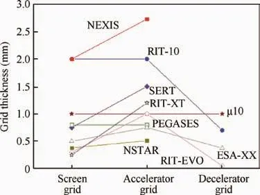
Fig.10 Thickness of grids used in significant ion thrusters.44–81
7.Materials
Ion engine grids need materials capable of working at elevated temperatures,but given that their main problems come from thermal expansion and sputter erosion,grid materials are selected based on their thermal and erosion properties.Molybdenum is the traditional material for the grids due to its low sputter erosion rate,ability to be chemically etched to form the aperture array,and good thermal and structural properties.Although optics made of other metals,especially titanium,have been fabricated and tested,carbon-based materials have developed as a better alternative for ion optics,particularly graphite(RIT-10,T5 and T6 accel grids),PG(HiPEP)and CC(μ10,NEXIS),because of their lower CTE(Coefficient of Thermal Expansion)and lower sputtering yield.
CTE describes how the grid will respond temperature changes.Molybdenum’s average linear CTE88is 4.8×10⁻⁶K-1,which is a low value for metals,while carbon-based materials have a CTE that oscillates between slightly negative and slightly positive(from-10-6K-1to 10-6K-1for graphite and PG89,90and from-2×10⁻⁶K-1to 2×10⁻⁶K-1for CC,91approximately),but it is always practically zero,which is important to maintain precise geometric alignment between screen and accel grid apertures.
Sputtering yield,an important magnitude to assess the sputter erosion in electric propulsion devices92–94,is the parameter that quantifies the sputtering behavior of a given material,and it is defined as the mean number of atoms removed from the surface of a solid per incident particle.These data are obtained through sputtering tests,whose main testing parameters are ion energy,incidence angle and material surface temperature.94Fig.12 shows the schematic arrangement of a sputtering test,which is conducted in a vacuum chamber(pressure between 10-5and 10-6Torr,1 Torr=133.32 Pa)and consists of a mobile sample holder that can be heated to change sample’s temperature and a fixed ion source.94–99The target sample is placed over the holder and bombarded with ions of different energies at different incidence angles and different sample surface temperatures.The erosion depth produced by the ion bombardment in different conditions is used to estimate the sputtering yield for each case.

Fig.12 Schematic layout of a sputtering test.
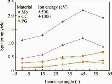
Fig.13 Sputtering test results for Mo,CC and PG under Xenon bombardment.97–100
Fig.13 shows the results of a sputtering test on Mo,PG and CC samples that were bombarded with Xenon ions of 500 eV and 1000 eV (1 eV=1.6×10⁻¹⁹J)energies at different incidence angles(0°,15°,30°,45°and 60°)and with sample surface temperature between 100 °C and 200 °C.97–100Normal incidence(0°)results in the lowest sputtering yield values,which increase for oblique incidence.Mo’s sputtering yield is more than double of PG’s and CC’s for the two ion energies,and PG and CC sputtering yields are very similar for all the incidence angles.
Fig.14 shows the relation between the average linear CTE and sputtering yield under Xenon bombardment of Mo,Ti,CC,PG and graphite.88–91,97,100,101Among carbon-based materials,with a CTE around zero,PG presents the lowest sputtering yield,followed closely by CC.Mo’s yield is twice that of CC and 30%higher than Ti’s,but Mo’s CTE is 50%lower than Ti’s.
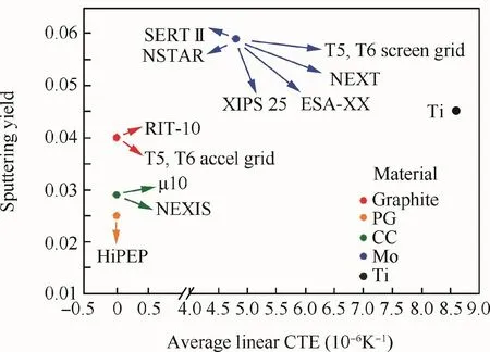
Fig.14 CTE vs sputtering yield of candidate materials for ion optics.88–91,97,100,101

Table 3 Basic properties of ion optics candidate materials.102–104
Although ion optics generally will not be subjected to high mechanical stresses,apart from CTE and sputtering yield,candidate materials for ion engine grid need to present acceptable mechanical properties.Table 3 shows the density,the strength and the elastic modulus of Mo,Ti,CC,PG and graphite.102–104Additionally,magnetic behavior of metals(Mo and Ti are both weakly paramagnetic)should be considered so that they have no impact on the thruster magnetic circuit.
Mo has a relatively high density,resulting in higher stress under dynamic loads.The high elastic modulus results in good rigidity,but this also increases stress under shock loads.Ti offers a 56%mass reduction over Mo while retaining good mechanical properties.PG,compared to Mo,has an order of magnitude lower strength and stiffness,but it is much more resistant than graphite.CC presents mechanical properties like metals but with a much lower density which,combined with its near-zero CTE and low sputtering,make it a very good option for ion engine grids.
Other materials,such as polycrystalline diamond film,105,106were proposed due to their favorable thermal and erosion properties,and other solutions,such as diamond coated Mo106and glass coated Mo,107were built and tested,but eventually discarded.
8.Ion optics fabrication technologies
Metallic grids and Carbon-Based Ion Optics(CBIO)have completely different manufacturing methods,but they all have in common that the plate( flat grids)or shell(dished grids)and the apertures are produced in different steps of the process.Fig.15 shows the fabrication process steps for ion optics of different materials,ordered by the complexity of the fabrication method.
For metallic grids,commonly made of Mo,the hole array is produced in the first place by photochemical etching over the Mo sheet.108A problem that arises from this method is that the shape of the resulting holes is not cylindrical,as shown in Fig.16,and cusps are formed close to the center thickness when the plates are etched from both sides.The minimum hole diameter is at the cusp and the maximum is on the grid surface.108,109
For flat grids,the etching operation is followed by a heat treatment,and after inspection,the Mo ion optics are ready for installation.However,metallic optics are often given a dished shape in order to reduce the effects of thermal expansion.For dished grids,metal sheets can be bent using a process called simultaneous hydroforming.In order to produce well matched ion optics,accelerator and decelerator grids are bent together.The two grids to be dished are first riveted together to ensure the proper hole alignment and placed over a rubber sheet.After that,grids and rubber are tightly clamped between a female die and a base plate,as shown in Fig.17(a).Hydraulic fluid is then pumped in through the base plate to in flate the rubber sheet,forcing the grids to take the shape of the female die as shown in Fig.17(b).The grids are later stress-relieved by placing them between matching male and female dies bolted together and heated in an inert atmosphere,and then cooled to room temperature.108
Mo grids can also be produced by swapping the etching and the hydroforming steps.110A photosensitive coating in the desired hole array pattern is applied on the flat Mo sheets,and then they are aligned,hydroformed and etched.
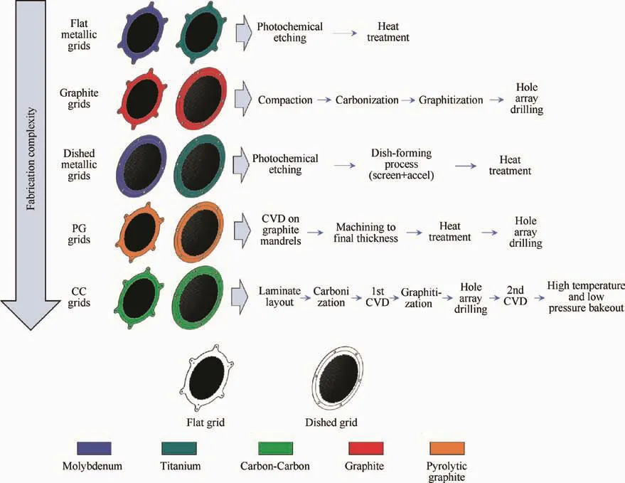
Fig.15 Different materials’ion optics fabrication processes.

Fig.16 Protruding tips resulting from etching of metallic plates on both sides.
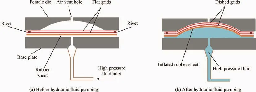
Fig.17 Hydroforming device to dish metallic grids.
Ti grids are fabricated following a similar method.111Titanium is corrosion resistant,which makes it difficult to etch,but titanium etching techniques were developed by medical industry to produce chemically etched parts of this material.112,113In order to be hydrostatically formed,titanium should be ductile enough.The usual measure of material ductility is elongation,and given that titanium is more ductile than molybdenum,ductility is not an issue.The high yield strength and low elastic module of Ti could result in a greater springback after the hydrostatic forming,but it was verified that spring values are within 10%of the final domed height,so they can be considered insignificant.111
The application of CNC(Computer Numerical Control)technologies for the fabrication of full metallic ion engine grids cannot be found in the literature,while the use of numerically controlled drilling for gridlets(subscale ion optics usually used for tests)aperture generation was reported.114
The fabrication CBIO with graphite,PG and CC composite require different manufacturing processes:
No information about the fabrication of graphite grids(RIT-10,T5 and T6 accel grids)is disclosed in the available literature.However,graphite manufacturing techniques are well understood,widely spread and usually used for electrodes production,89,115aerospace fabrication116,117and other commercial applications.Graphite products are manufactured by a compaction process from a mixture of carbon filler and organic binder which is subsequently carbonized and graphitized.The compaction,which can be achieved by isostatic molding,is followed by a carbonization aimed to release the volatiles and harden the material.After the carbonization,which may last from few days to several weeks,a graphitization of similar duration takes place to increase the material resistance.88Plates of commercial graphite had apertures drilled into the surface to create gridlets for several tests.114,118In the same way,the complete hole array could be machined on a larger graphite plate or shell to produce full ion optics.Graphite grids are commonly used in ion sources for ground application.119
PG fabrication is based on the deposition of a gaseous precursor on a substrate by an apparatus such as a cold-wall reactor.PG grids are grown on high-purity graphite mandrels,where they take on the desired geometry.Once the mandrels have been produced and they are ready to use,a Chemical Vapor Deposition(CVD)of carbon takes place.Carbon atoms are deposited,layer after layer,until the grid takes shape.Grids are grown oversize and later machined to the final thickness.In this way,there is a better control of dimensional tolerances.After that,a heat treatment is applied to relieve the stresses induced by the machining.Finally,the apertures are mechanically drilled.120Both flat and dished PG grids are manufactured through this method,changing the shape of the mandrel.
The production process for CC composite dished ion optics for the NEXIS ion thruster is accurately described by Beatty et al.67The first step is to order custom-made prepreg materials of the right thickness and the fabrication of graphite layup tools.Once the two-part concave-convex mold is ready,the layers are alternatively placed on the tool,compacted and cured in a heated press without need for an autoclave.When the carbon-phenolic laminate is finished,the phenolic matrix is reduced to carbon by high-temperature firing in an oxygen-free atmosphere.After the carbonization,additional carbon is added to the laminate through CVD.Later,the grids are subjected to a fiber graphitization treatment at high temperature to increase the stiffness of the laminate fibers.On the next step,the holes’center points are positioned and laser-drilled.Finally,another densification by CVD and a high-temperature low-pressure vacuum bake-out in autoclave are applied.
When fabricating CC flat grids,Snyder et al.followed a similar process.120The main differences were that the curing of the laminate was carried out in autoclave and that the carbonization of the phenolic resin was followed by a Chemical Vapor Infiltration(CVI)process,instead of CVD.Additionally,they suggest Electric Discharge Machining(EDM)or ultrasonic etching as the technique to create the apertures on the CC laminate.
These methods are lengthy and complex,but,as CC fabrication is common in aerospace,121–123they have the advantage of being predictable and repeatable.88The most timeconsuming steps are the CVD/CVI processes,which require tens of hours to tens of days to be completed.124,125For instance,when manufacturing dished grids,the carbonized laminates are placed in a vacuum chamber at high temperature in the presence of carbon-bearing gas for 200 h.67
Apart from these manufacturing methods,ion thruster grids have also been fabricated through other processes like resin injection into a carbon fiber preform126:Several layers of finely woven carbon fabric are used to establish a preform,which is then pressed against a mold containing an array of precisely machined steel needles.The preform is then impregnated with resin and cured,to form a flat perforated panel.Apertures are achieved by the penetration of conical needles when molding.A common mold hardware is used to fabricate both the screen and accelerator grids,ensuring coaxial alignment of all grid apertures between all grid sets.
New fabrication technologies can have potential application for ion optics.The increasing availability of materials and the improved precision of additive manufacturing powder bed techniques,127–130already used for aerospace,131–135and the recent development carbon-based 3D printing136,137could be used in the near future for ion engine grids manufacturing.
9.Conclusions
GIE is one of the most developed electric propulsion solutions,whose main feature is that the propellant ionization process and the ion acceleration process are physically separated.The technology has been successfully applied for scientific exploration,numerous prototypes have been tested and some thrusters are commercially available.Ion engine grids,the components responsible for ion acceleration,are at the same time the parts that limit the service life of the GIE due to their erosion.
Despite the fact that the extraction system of each GIE is specifically designed and built according to the propellant and the specific needs of the thruster,there are some common features to ion optics installed in the GIE whose information has been disclosed:
(1)Typical ion extraction systems use two-grid(screen+accel)or three-grid(screen+accel+decel)configurations with flat,outward-dished or inward-dished shapes.Smaller thrusters(diameter≤15 cm)frequently use three flat grids(RIT-10,μ10,etc.),and among bigger thrusters(diameter>15 cm),two outward-dished grids(NSTAR,NEXIS,NEXT,etc.)is the most common configuration.Screen grid is biased to a positive high voltage supply,while accel grid is connected to a negative potential.Decel grid,when used,has no electric potential and mainly acts as a shield to protect accel grid from charge-exchange ions.
(2)Most of the ion optics installed in significant thrusters have similar geometries.Screen grid is designed with a minimum thickness to increase the effective transparency,accel grid tends to be thicker for better erosion resistance and decel grid,when included,is normally thinner than screen grid.Grid apertures,typically circular and packed in a hexagonal array,are larger in the screen grid than in the accel grid.Decel grid apertures are usually larger than accel grid’s holes,and can have smaller,the same or larger sizes compared with screen grid’s apertures.The gap between screen and accel grid,both during assembly(cold gap)and operation(hot gap),should be smaller than aperture diameters.
(3)In order to address erosion and thermal expansion problems during the GIE operation,ion optics materials are selected based on their thermal(low CTE)and erosion(low sputtering yield)properties.Mo is the traditional material for the grids,and although metals such as Ti have been proposed as an alternative,carbon-based materials(graphite,PG and CC)have been developed as a better solution for ion optics.Among them,CC presents the best balance of CTE,sputtering yield and mechanical properties.From the fabrication point of view,metallic ion optics are easier to produce and have been used by all the countries that developed the GIE technology.On the other hand,the manufacturing method of carbon-based grids is lengthier and more complex,and just the US and Japan have reported the use of this type of extraction systems.
Currently many countries use GIE technology to propel their satellites and space missions.Although the geometry of the ion optics is mainly decided by the propellant,the configuration and the materials of the grids depend on the size of the grids,the design of the thruster and the available fabrication technologies.While countries such as US and Japan developed CC grids for their thrusters,the European T5 and T6 thrusters opted for a two-material extraction system with inward-domed grids for their recent missions using GIE.As the interest in GIE and its applications grow,new technologies such as additive manufacturing are more likely to be applied to the development of new material solutions and fabrication processes for ion optics,since increasing the quality and the life of the ion extraction system will increase the service life of the ion thruster.
杂志排行

CHINESE JOURNAL OF AERONAUTICS的其它文章
- Aeroelastic stability analysis of heated flexible panel subjected to an oblique shock
- Damage localization eあects of the regenerativelycooled thrust chamber wall in LOX/methane rocket engines
- Receptivity and structural sensitivity study of the wide vaneless diあuser flow with adjoint method
- Large-eddy simulation and linear acoustic modeling of entropy mode oscillations in a model combustor with coolant injection
- Development of secondary flow field under rotating condition in a straight channel with square cross-section
- Nonlinear bending analysis of a 3D braided composite cylindrical panel subjected to transverse loads in thermal environments