Comparative Study of Different Decoupling Schemes for TITO Binary Distillation Column via PI Controller
2018-07-31MohamedHamdyAbdalhadyRamadanandBelalAbozalam
Mohamed Hamdy,Abdalhady Ramadan,and Belal Abozalam
Abstract—This paper presents a comparative study of different decoupling control schemes for a two-input,two-output(TITO)binary distillation column via proportional-integral(PI)controller.The key idea behind this paper is designing two novel fuzzy decoupling schemes that depend on human knowledge,instead of the system mathematical model used in conventional decoupling schemes.Based on conventional and inverted decoupling schemes,fuzzy and inverted fuzzy decoupling schemes are developed.The control effect is compared using simulation results for the proposed two schemes with conventional decoupling and inverted decoupling.The proposed fuzzy decoupling schemes are easy to realize and simple to design,besides they have a good decoupling capability.Two methods are used to prove asymptotic stability of each loop and the entire closed-loop system by applying the proposed fuzzy decoupling-based PI controller.The Wood and Berry model of a binary distillation column is used to illustrate the applicability of the proposed schemes.
I.INTRODUCTION
M ANY researchers have focused on control methods for multiple-input and multiple-output(MIMO)systems.MIMO with N input/output processes are characterized by significant interactions between their inputs and outputs.The control of MIMO processes is usually implemented using sets of single-input single-output(SISO)control loops.Interaction is a phenomenon that the loop gain in one loop depends on the loop gain in another loop,this interaction between controlled loops leads to deterioration in the control performance of each loop[1]-[3].The control of MIMO processes requires proper input-output pairing and development of decoupling compensator unit.Decoupling control has emerged as one of the most popular techniques in the industrial process.The basic idea is to weaken,or even eliminate,the interactions between different input and output signals by decoupling methods.Then,the modern and advanced control methods could be applied to the separate SISO subsystems.And it is easy for industry engineers to use various advanced control strategies into practical works.
A survey on theory and developments of decoupling control has been discussed by[4].Some of the decoupling control methods found in literatures could be classified under the following topics,showing the interest that rose in the last years:[5]-[8]based their design on decomposing the problem into two parts:1)decoupling the system using conventional decoupling to decrease interaction,and 2)designing the controllers using some decentralized method.[9]-[11]included work that discusses a methodology of multivariable centralized control based on the structure of inverted decoupling.This method has presented for general n×n processes by obtaining very simple inclusive expressions for the controller elements with a complexity independent from the system size.The last two methods are easy but require a complete model of the system.Usually operator’s knowledge plays an important role in complex industrial processes.This knowledge may be integrated in the control system by the fuzzy inference system(FIS),independent of model-based analysis.FIS allows getting the control actions from input variables by using linguistic formulated rules,so their conception is more simplified.Fuzzy control has long been applied to industry with several important theoretical results and successful ones[12]-[17].In recent years,many schemes of fuzzy decoupling have been developed in[18]-[22],such as the proposed fuzzy compensator of interactions in[19]acts as a feedforward controller.The outputs of the monovariable controllers are considered as the inputs of the fuzzy compensator,which produces compensation signals added to the single loop control signals for minimizing the effect of interactions.In[20],based on the conventional decoupling,fuzzy decoupling elements are developed to get the purpose of decoupling,the inputs of each fuzzy decoupling element are the output of PI controller and its differential,each element produces a compensation signal which is added to the single loop control signal for minimizing the effect of interactions.
Distillation column is one of the most important operation units in terms of control in chemical engineering.It is used in chemical industry to separate liquid mixtures into their pure components by the application and removal of heat[23].It consumes a huge amount of energy in both heating and cooling operations.A robust control of distillation column’s operation is important,due to reduction of energy consumption during operation,but the robust control implementation is difficult due to the phenomenon of interaction or coupling,which exists between various control loops of the distillation column[24],[25].In addition,distillation column is usually nonlinear,multivariable,and it is subject to constraints and disturbances.
In this paper,a control system for a binary distillation column which,dynamically,behaves as a TITO system has been implemented.The emphasis is to determine a decoupling control,where specific inputs and outputs are paired.This decoupling control is achieved using fuzzy logic,to reduce the reliance on model-based analysis.Also,a comparative study is done using different decoupling schemes with two PI controllers to control the two composition control loops of the binary distillation column.Based on conventional and inverting decoupling schemes,fuzzy and inverting fuzzy decoupling schemes are developed.To the authors’best knowledge,there are no results considering inverted decoupling using fuzzy logic.The proposed schemes are simple and easy in driving fuzzy rules.
This paper is organized as follows.The distillation column model description is given in Section II.Section III presents the design of decoupling control schemes.Section IV presents the two PI controller designs with stability analysis.The simulation results are given in Section V.Finally,the conclusion is given in Section VI.
II.DISTILLATION COLUMN MODEL
There are many types of distillation columns based on different classifications such as:batch,continuous,binary,multi-product,tray and packed[25].Consider an MIMO binary distillation column with a given feed shown in Fig.1,which has five manipulated inputs U=[L V D B VT]T.These are reflux flow rate,boil up vapour flow rate,top product flow rate,bottom product flow rate and overhead vapour flow rate,respectively,and five controlled outputs Y=[XDXBMDMBP]T.These are top and bottom compositions,condenser and re-boiler levels and column pressure.
Different control configurations result from different pairing between controlled and manipulated variables[26].The distillation column configuration to be studied is LV control configuration as shown in Fig.1.In this configuration,the manipulated variables are{L and V}and the controlled output variables are{XDand XB}.The Wood and Berry distillation column is a TITO system that has been studied extensively.It is described by the following model[1]:


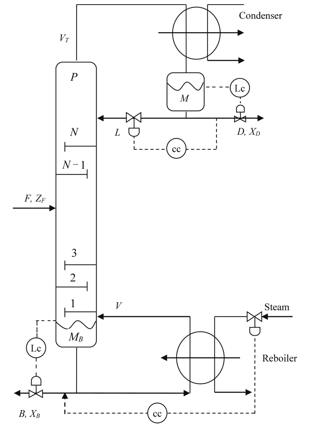
Fig.1.Binary distillation column with LV configuration.
III.DECOUPLING CONTROL SCHEME DESIGN
Consider a TITO system described in transfer function matrix G(s),the purpose of the decoupling matrix D(s)is to transform the process as seen by the controller from G(s),a full block matrix,to Q(s)which is a diagonal matrix,and then each diagonal controller deals with each loop as SISO loop where

and

A.Scheme 1(Conventional Decoupling)
To eliminate the effect of the coupling between loops in the distillation column,a conventional decoupling is added before the distillation column as shown in Fig.2.The transfer function between inputs and outputs is given by

where C1and C2are flow rate control output signals from each loop PI controller,anda decoupling matrix,where R12(s),R22(s)are the elements of the decoupling matrix.

Fig.2.Distillation column with conventional decoupling scheme.
Equation(4)can be written as
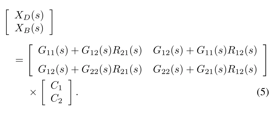
To remove the interaction,the following terms in(5)should be equal zero

From(6)and(7)
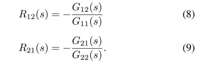
The disadvantage of this approach is that the decoupling matrix will be complex with n×n models.
B.Scheme 2(Fuzzy Decoupling)
A fuzzy decoupling scheme consists of two elements:Fuzzy1and Fuzzy2as shown in Fig.3,each one has two inputs and one output.Fuzzy1has inputs(C1,dXB)and output signal F1,Fuzzy2has inputs(C2,dXD)and output signal F2where C1and C2are the outputs of two PI controller loops,also dXDand dXBare the rates of change of the top and bottom product composition,respectively.The output signals F1and F2are used as a flow rate compensation signal for the other loop,where L=(C1+F2),and V=(C2+F1).From the concept of fuzzy logic,each fuzzy decoupling element consists of the following four major components:Fuzzification,inference engine,rule base and defuzzification.Fuzzification comprises the process of transforming crisp values into grades of membership for linguistic terms of fuzzy sets.The membership function is used to associate a grade to each linguistic term.To the best of our understanding,the triangular membership function is simple to implement and fast for computation.So,three symmetrical triangular membership functions for Fuzzy1and Fuzzy2variables are named as Small(S),Medium(M),and High(H)as shown in Fig.4.The inference engine is considered as the decisionmaking-logic that determines how the fuzzy logic operations are performed based on the knowledge base(rule base),the inference engine of Fuzzy1and Fuzzy2is based on Mamdani inference system.The general form of the rule base is based on IF-THEN rule,for example
input1is S AND input2is S THEN output is S.
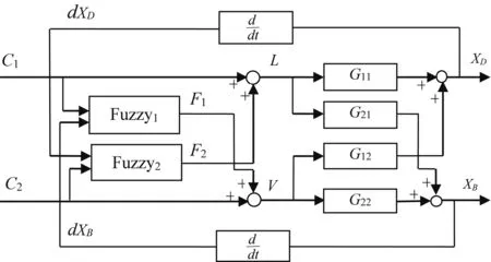
Fig.3.Block diagram of fuzzy decoupling scheme.
The transformation from a fuzzy set to a crisp number is done through defuzzification;center of gravity method is used for defuzzification.
The derivation of the fuzzy decoupling control rules can be obtained directly from the dynamic behavior of binary distillation column[27],as follows:increasing L will increase XDand XB,and increasing V will decrease XDand XBand vice versa,so changes in L and V will counteract each other.So:
1)When the input of a certain loop is medium(steady state region)then its compensation signal to the other loop will be medium.For example
If C1is M and dXBis(S or M or H)then F1is M.

Fig.4.Triangular membership function.
2)The direction of the change in the compensation signal should follow the direction of the change in the input signal,taking into account the change in the output direction of the other loop.For example
If C1is S and dXBis S then F1is S.
In this rule,in which dXBis small,this will be an indication that C2is high,i.e.,opposite to the required compensation signal F1.So,F1must be small.
If C1is S and dXBis H then F1is M.
In this rule,in which dXBis high,this will be an indication that C2is small,i.e.,similar to the required compensation signal F1.So,F1must be medium.
Therefore,the fuzzy decoupling control rules can be easily obtained as shown in Tables I and II.

TABLE IFUZZY1 RULES FOR FUZZY DECOUPLING CONTROL

TABLE IIFUZZY2 RULES FOR FUZZY DECOUPLING CONTROL
C.Scheme 3(Inverted Decoupling)
With inverted decoupling approach the decoupling transfer function complexity is independent of the system size[9].As shown in Fig.5,the decoupling matrix D(s)is split into two matrices:a matrix Dd(s)in the direct path(between controller outputs C and process inputs U)and a matrix Do(s)in a feedback loop(between process inputs U and controller outputs C).The matrix Dd(s)must have only nonzero diagonal elements,since there must be only a direct connection for each process input.Note that these relationships are not required in the matrix Do(s).Additionally,since the signal flow direction in Do(s)is opposite to that of Dd(s),the corresponding elements of Do(s)are opposite to that of Dd(s),the corresponding elements of Do(s)must equal zero and are the same as transposing non-zero elements of Dd(s).For instance,in a 2×2 process,if element Dd(2,1)is specified as a direct path between U2and C1,there will be no feedback from U2toward C1,and thus,the element Do(1,2)must be zero.Following the decoupling representation shown in Fig.6,the expression of the decoupling matrix D(s)is obtained as follows:


Fig.5.Matrix representation of inverted decoupling for SISO.
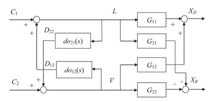
Fig.6.Distillation column with inverted decoupling.
From(3)and(11),one can get

Depending on the system size,there are different configurations with different cases for the choice of inverted decoupling elements;the proper configuration with proper case depends on the realizability of the decoupling elements.In this work,case 1 from configuration(1-2)[9]is used as follows:
Configuration (1-2): In this configuration elements Dd(1,1),Dd(2,2),diagonal elements in Dd,and Do(1,2),Do(2,1),off diagonal elements of Do,are selected,other elements equal zero.

From(12),one can get

Thus d11=q1/g11,do12=-g12/q1,do21=-g21/q2,d22=q2/g22.
Two of these elements are set to unity,and so only two elements need to be implemented.Usually,the two elements chosen to be equal to one are the elements in the direct way,that is,the elements of the matrix Dd.However,this case is only one of the four possible cases according to the two elements chosen to be equal to unity.Fig.6 shows case 1 scheme which is applied to binary distillation column.
D.Scheme 4(Inverted Fuzzy Decoupling)
From Case 1,configuration(1-2)of inverted decoupling and the concept of fuzzy decoupling,the fuzzy inverted decoupling is developed as shown in Fig.7.Inverted fuzzy decoupling consists of two elements:Fuzzy1and Fuzzy2,each one has two inputs and one output.Fuzzy1has inputs(U1,dXB)and output signal F1,Fuzzy2has inputs(U2,dXD),and output signal F2,where U1=L=(C1+F2)and U2=V=(C2+F1).Each output signal(F1or F2)is used as a compensation signal for the other loop.The membership functions of input and output variables for Fuzzy1and Fuzzy2are shown in Fig.4,also according to the dynamic behavior of distillation column mentioned in previous section.The inverted fuzzy decoupling control rules are shown in Tables III and IV.Inverted fuzzy decoupling has the advantage of simplicity in design for n×n processes and using fuzzy logic in designing decoupling elements.
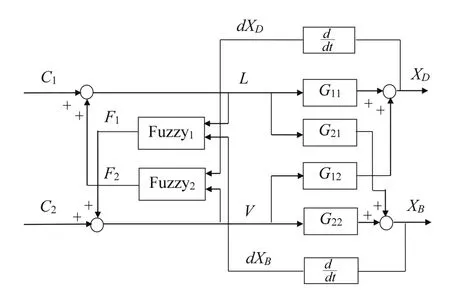
Fig.7.Block diagram of inverted fuzzy decoupling.

TABLE IIIFUZZY1 RULES FOR INVERTED FUZZY DECOUPLING CONTROL

TABLE IV FUZZY2 RULES FOR INVERTED FUZZY DECOUPLING CONTROL
IV.CONTROLLER DESIGN
The controller design consists of two steps,1)the decoupling elements based on Wood and Berry distillation column mathematical model are calculated,2)the PI controller parameters for each loop are designed individually according to stability analysis.
A.Calculating Decoupling Elements
The conventional and inverted decoupling consists of two terms D12(s)and D21(s).From(1),(8),(9)and(14),these terms can be written as

Fuzzy and inverted fuzzy decoupling schemes are designed in the following.The suggested fuzzy rules of Fuzzy1and Fuzzy2are shown in Tables I-IV,three symmetrical triangular membership functions for the Fuzzy1and Fuzzy2inputs,and output variables are chosen as shown in Fig.4.The low and high limits of the universe of discourses for these variables are as follows.
For the fuzzy decoupling elements:C1=[0.18 0.33]T,C2=[-0.042 0]T,dXB=[-0.2 0.1]T,and dXD=[-0.025 0.025]T,F1=[0.01 0.172]T,and F2=[-0.05 0]T.
For the inverted fuzzy decoupling elements:U1=[0.1 0.22]T,U2=[0 0.09]T,dXB=[-0.012 0.006]T,and dXD=[-0.01 0.08]T,F1=[0 0.01]T,and F2=[0 0.12]T.
B.PI Parameters Design
The design of PI parameters of each loop has been done using signal constraint block from MATLAB library(Simulink design optimization),by specifying the desired signal response and attaching the signal constraint block to the feedback signal to optimize the model response to known inputs.Simulink design optimization software tunes parameters in the model to meet specified constraints.Each loop has been designed individually with closing the other loop.Trial and error was used to reach the optimum performance by making little changes in the parameters.The parameters of the two PI controllers are shown in Table V.The top composition PI controller is chosen as the direct action controller which means that the controller output rises if the measurement increases,but the bottom composition PI controller is chosen as the reverse action controller which means that the controller output drops if the measurement increases.PI controllers are chosen since the flow control is considered as a fast process,and using derivative action with a fast process usually leads to instability.

TABLE VPI CONTROLLER PARAMETERS
B.1 Stability Analysis
Two different methods are used to perform stability analysis.In the first method,multivariable systems are decomposed into n SISO subsystems using system structural decomposition,and then stability analysis is performed for each loop independently.In the second one,stability analysis is performed using TITO tool.
B.1.1 System Structural Decomposition
For system structural decomposition in[8]stability analysis is done without using decoupling element as follows:
The steady state transfer function of the proposed system“seen”from the free input L to the free output XDis

Also,the steady state transfer function of the proposed system “seen”from the free input V to the free output XBis

where K1,K2are the transfer functions of PI controllers for loop1and loop2,respectively,and formulated as

where i=1,2.
Applying Nyquist theorem to each individual loop transfer function in(16)and(17)which is multiplied by the transfer function of the controller(18)of the same loop is shown in Figs.8 and 9.According to Theorem 1 in[8],each individual element of G(s)and its SISO independent subsystems do not have poles in the right hand plane,so the system with the decentralized PI controller is stable as the Nyquist contour of each equivalent open loop transfer function does not encircle point(-1,0),i.e.,

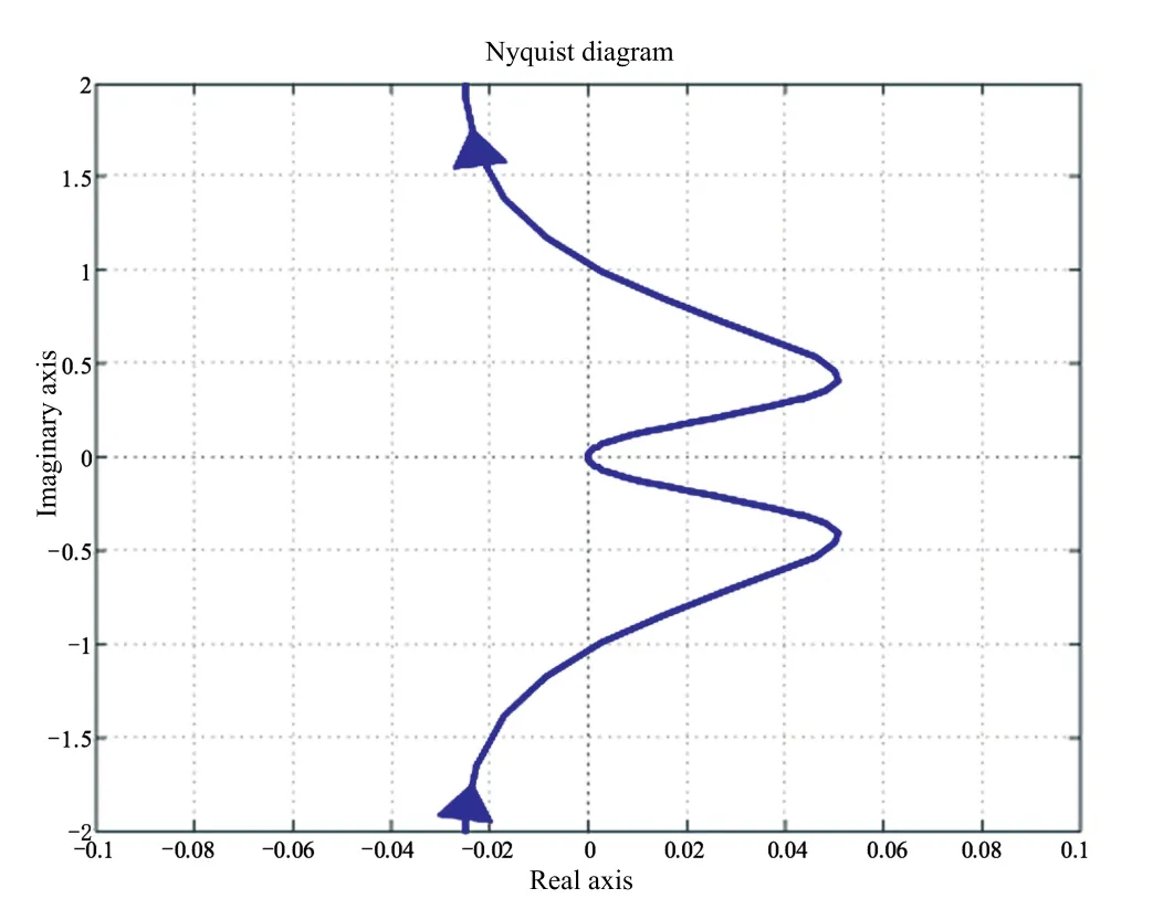
Fig.8.Nyquist diagram for loop1.
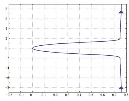
Fig.9.Nyquist diagram for loop2.
B.1.2 TITO Tool
TITO tool is a tool developed by[8]to design decentralized PID controllers for multivariable systems with conventional decoupling,and specifications analysis and time response simulations can also be obtained using this tool.In this work TITO tool is used to obtain the structural direct Nyquist arrays(SDNA)for the proposed distillation column model with the designed conventional decoupling elements as shown in Fig.10.The system with two designed decentralized PI controllers is stable as the Nyquist contour of each loop does not encircle point(-1,0).
V.SIMULATION RESULTS
The decoupling schemes proposed in previous section have been tested on Wood and Berry binary distillation column mathematical model.Simulation work has been done in Simulink and Fuzzy toolbox in the environment of MATLAB.

Fig.10.DNA diagram using TITO tool(left)loop1 and(right)loop2.
The simulation results are obtained for the closed loop response of each loop,by changing the decoupling scheme with the same PI controller parameters.Figs.11 and 12 show the response of top and bottom compositions for changing the top composition set point and keeping bottom composition without change(r1=1,r2=0)at simulation time(0 to 500).From the results,the performance of the top composition obtained with inverted fuzzy decoupling is better than those obtained with other schemes as shown in Fig.11.Moreover,bottom composition has smaller change with inverted fuzzy decoupling than others as shown in Fig.12.The control signals of two PI controllers are shown in Figs.13 and 14.The final control signals(U1,U2)are shown in Figs.15 and 16.

Fig.11.Response of top composition with different decoupling.
VI.CONCLUSION
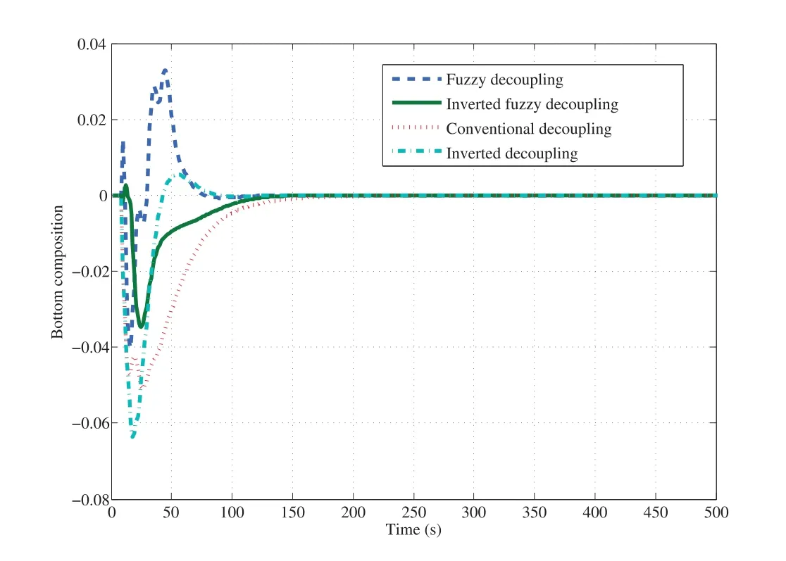
Fig.12.Response of bottom composition with different decoupling.
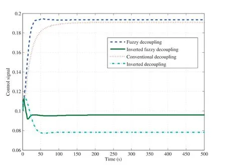
Fig.13.Loop1 PI control signal.

Fig.14.Loop2 PI control signal.

Fig.15.Response of U1.

Fig.16.Response of U2.
In this paper,applying decoupling control using different decoupling schemes for a binary distillation column is presented,besides the PI controller is designed for each loop after decoupling.The key idea of the design procedure is to introduce decoupling elements in cascade with the distillation column to reduce the interactions that occur between their strategic variables.The main advantage of using decoupling control is the simplicity in determining the controller parameters since each loop is treated independently.The problem of mathematical models is solved by using fuzzy methods in implementing decoupling elements.Fuzzy and inverted fuzzy decoupling schemes are developed based on conventional and inverted decoupling ones.A comparison between fuzzy and inverted fuzzy decoupling schemes and other decoupling schemes is presented.The obtained simulation results show that the performances obtained with fuzzy and inverted fuzzy decoupling schemes are better than those obtained by using other decoupling schemes.Future research will extend the results of this paper to develop adaptive fuzzy and inverted adaptive fuzzy decoupling schemes.
杂志排行
IEEE/CAA Journal of Automatica Sinica的其它文章
- Polyhedral Feasible Set Computation of MPC-Based Optimal Control Problems
- The Power Allocation Game on A Network:A Paradox
- Finite Frequency Fuzzy H∞Control for Uncertain Active Suspension Systems With Sensor Failure
- Analysis of the Caratheodory’s Theorem on Dynamical System Trajectories Under Numerical Uncertainty
- Modified Cuckoo Search Algorithm to Solve Economic Power Dispatch Optimization Problems
- Robust Leader-Following Output Regulation of Uncertain Multi-Agent Systems With Time-Varying Delay
