Numerical analysis of shell-side flow-induced vibration of elastic tube bundle in heat exchanger *
2018-05-14JiadongJi季家东PeiqiGe葛培琪WenboBi毕文波
Jia-dong Ji (季家东), Pei-qi Ge (葛培琪) , Wen-bo Bi (毕文波)
1. School of Mechanical Engineering, Anhui University of Science and Technology, Huainan 232001, China
2. School of Mechanical Engineering, Shandong University, Jinan 250061, China
Introduction
The heat exchanger[1-3]is an energy saving equipment, widely used for the heat exchange between different kinds of media with different temperatures. In a conventional heat exchanger, the vibration induced by the internal fluid flow may lead to damages of the heat transfer elements. Numerous studies focused on the influence of the shell-side cross flow on the vibration characteristics of the heat transfer equipment[4-8]. For the design and the improvement of the conventional heat exchangers, especially, the shell-and-tube heat exchangers, one of the key problems is to prevent or reduce the flow-induced vibration of the heat transfer equipment[9,10]. However,it is very difficult to do so.
The positive effect of the flow-induced vibration is to enhance the heat transfer, as was proposed as a novel approach to deal with the vibration damage in conventional heat exchangers. Cheng et al.[11,12]presented a novel elastic tube bundle to enhance the heat transfer performance. Under the working conditions,the elastic tube bundle vibrates with a low frequency and a small amplitude around its equilibrium position,driven by the fluid flow around it. It is shown that the average tube outside convective heat transfer coefficient of the elastic tube bundle is more than 2 times larger than that of the traditional rigid element in the tube type heat exchanger. Besides that, many new improvements and designs were made based on the elastic tube bundle in order to further improve the heat transfer performance of the elastic element[13-15]. An experimental platform for the shell-side flow-induced vibration of a single row elastic tube bundle was set up by Su[16], and the flow-induced vibration frequency of the single row elastic tube bundle was tested at different shell-side water inlet velocities. The results indicate that the harmonic frequency occurs for a low shell-side fluid flow speed.
Because of the complexity of the structure, the surrounding fluid domain, and the working conditions,it is very difficult to obtain exact analytical solutions.Up to now, the flow-induced vibration responses of the elastic tube bundle were mostly studied experi-mentally. The present study focuses on the flow induced vibration responses of the elastic tube bundle subjected to shell-side cross flow. The weak coupling method and the fluid solid interface are used to solve the fluid-structure interaction problem with consideration of the geometry and physical natures. The effects of the shell-side fluid flow velocity and the structural parameters, including the wall thickness and the external diameter, on the flow-induced vibration responses, are discussed. The research may shed some new light on the mechanism of the heat transfer enhancement, and help the optimization of the tube bundle structure and the improvement of the heat exchanger.
1. Numerical simulation approach
1.1 Geometric model
The structure of the elastic tube bundle discussed in this paper is shown in Fig.1. It can be seen that the elastic tube bundle consists of four circular copper tubes, and they are connected together by two stainless steel blocks, III and IV. I and II are two fixed ends, and they are installed on the tube-side fluid inlet and outlet standpipes, respectively.R1,R2,R3andR4are the radiuses of the four circular copper tubes.rand δ are the outer radius and the wall thickness of the circular copper tube, respectively.x,yandzare the three coordinates of the Cartesian coordinate system. φ is the angle between the stainless steel blocks III and the horizontal directionz.

Fig.1 (Color online) Structure of the elastic tube bundle
Figure 2 shows the schematic diagram of the fluid domain. The bottom of the computational fluid domain in Fig.2 is the inlet of the shell-side fluid, and the top is the outlet of the shell-side fluid.Ris the radius of the computational fluid domain. A and B are the two monitor points on the top surface of the stainless steel blocks III and IV, respectively, and both of them are used to detect the displacements inx-,yandz- directions induced by the shell-side cross flow.

Fig.2 (Color online) Schematic diagram of the computational fluid domain
Table 1 shows the structural parameters of the elastic tube bundle in the study. In order to study the effect of the wall thickness on the flow-induced vibration responses, the wall thickness of the copper tube bundle varies from 1 mm to 2 mm. Similarly, the outer radius of the copper tube bundle varies from 7 mm to 12 mm in order to study the effect of the outer radius.

Table 1 Structural parameters of the elastic tube bundle
1.2 Mathematical model and solution method
In view of the geometry and physical natures, the standardk-ε turbulence model is chosen to simulate the turbulent flow. The basic equations in ak-ε model for an incompressible flow can be expressed as follows[17]:
Continuity equation

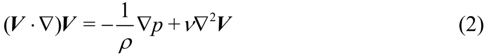
Momentum equation
k-εequations

whereVdenotes the fluid velocity,pis the pressure, ρ is the density of the fluid, ν is the kinematic viscosity of the fluid,kand εare the turbulence kinetic energy and the turbulent eddy dissipation,respectively, μland μtare the viscosity of the laminar and turbulent flows, respectively,σkand σεare the diffusion Prandtl numbers (σk=1.0 and σε=1.3), andCμ,Cε1andCε2,are the turbulent model constants (Cμ=0.09,Cε1=1.44andCε2=1.92).
The dynamic balance equation for the structure can be expressed as in the following form based on the boundary conditions and the dynamic balance condition[18].

whereMs,CsandKsare the mass matrix, the damping matrix and the stiffness matrix of the structure, respectively, ς denotes the nodal displacement vector,0τ denotes the internal force of the structure,andsτ denotes the fluid force acting on the structure.
The interaction between the flow field and the structural dynamics typically takes place through the fluid-structure interface. The dynamic and kinematic conditions on the interface are as follows[19,20]:

wherenis the surface normal, τis the stress, and the subscriptssandfindicate the structure and the fluid, respectively.
In the present study, the uniform fluid velocity is taken as the inlet boundary condition, and the pressure outlet boundary condition is used at the outlet of the computational fluid domain. The fluid solid interface is imposed on the inner wall of the computational fluid domain. In addition, the elastic tube bundle is fixed at the two cross sections of the fixed ends I and II. The corresponding outer wall of the elastic tube bundle is set to be the fluid solid interface. Furthermore, the finite volume method and the finite element method are used to discrete the fluid and structure motion equations, respectively.
According to the solution strategy, the numerical methods for the fluid-structure interaction problems can be divided into the weak coupling methods and the strong coupling methods. A weak coupling method is chosen to solve the fluid-structure interaction problem with consideration of the geometry and physical natures in this paper. The solution process is as follows: Firstly, the control equations in the fluid domain are solved based on the initial boundary conditions, to obtain the pressure distribution on the fluid-structure interface. Secondly, the pressure distribution on the corresponding surface of the elastic tube bundle is applied by the load transfer on the fluid structure interface, the transient dynamic analysis is conducted in the structural domain, to obtain the displacement of the elastic tube bundle. Thirdly, the structural analysis results are used as the new boundary conditions, to solve the control equations in the fluid domain again, and to obtain the new pressure distribution on the fluid-structure interface. Fourthly,the pressure distribution is applied to the structure domain again, to conduct the transient dynamic analysis in the structural domain. Finally, the above process is repeated until the results satisfy the convergence criterion.
1.3 Verification of numerical method
The ANSYS mesh-generator and the ICEM CFD mesh-generator are employed to perform the generation and the meshing of the elastic tube bundle and the computational fluid domain, respectively. Figures 3, 4 show the respective grid distribution of the computational structural domain and the computational fluid domain. It is seen that the mesh grids of the computational structural domain include the structured grid (four circular copper tubes) and the unstructured grid (two stainless steel blocks), while the mesh grids of all computational fluid domain are the structured grids. In the methods of meshing, the structured grid can fit regular shape with good form meshes, which are easily adapted and refined. There are totally 9366 elements with 54777 nodes of the elastic tube bundle in the computational structural domain, and 329708 elements with 309350 nodes of the fluid in the computational fluid domain.
In order to verify the independence of the grids,the number of grids for the fluid and structural domains and the local grid density in the fluid domain around the elastic tube bundle are increased. There are totally 13146 elements with 58116 nodes in the computational structural domain, and 626348 elements with 596502 nodes in the computational fluid domain after the grid refinement. Table 2 shows the flow induced vibration frequency and amplitude at the monitor point B inx-direction before and after the grid refinement when the shell-side water inlet velocity is 0.8 m/s. The numerical simulations are carried out with a constant tube wall thickness (δ=1.5mm)and a constant tube external diameter (r=10.0mm).The other parameters of the structural and fluid domains are consistent with those in Table 1.

Fig.3 (Color online) The grid distribution of the computational structural domain

Fig.4 (Color online) The grid distribution of the computational fluid domain
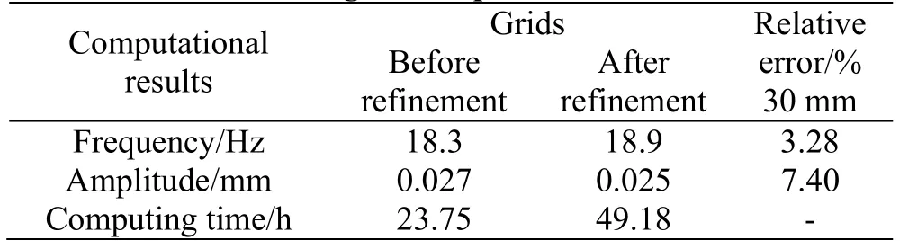
Table 2 Verification of grid independence
It can be seen that the numerical results before and after the grid refinement have a good consistency,and the largest relative error is less than 7.5%.Therefore, little effect is observed on the numerical results by increasing the grid number and the local grid density. On the other hand, the computing time after the grid refinement is about 2.1 times of that before the grid refinement. Thus, the grid arrangement before the grid refinement is used in the following discussions by taking both the accuracy and the computational time into account.
The flow-induced vibration frequency of the elastic tube bundle subjected to the shell-side cross flow at different water inlet velocities was investigated experimentally by Su[16]. However, the shape of the elastic tube bundle used in the experiment is slightly different from that described in this paper.The elastic tube bundle described in this paper has smaller low-order natural frequencies, so it is easy to achieve a vibration with a low frequency and a small amplitude under the impact of the low speed shell-side cross flow. According to the experiment, the shape and structure parameters of the elastic tube bundle are consistent with Ref. [16], and the mathematical model is established based on the numerical method mentioned above. The numerical and experimental results of the shell-side flow-induced vibration frequency and acceleration inx-direction at two different shell-side water inlet velocities are shown in Table 3.
It can be seen from Table 3 that the simulation results at different water inlet velocities are in good agreement with the experimental ones, and the largest relative error is less than 9%. Thus, the correctness and the reliability of the numerical method are validated.
2. Results and discussions
2.1 Effect of inlet velocity on vibration responses
In order to investigate the effect of the shell-side water inlet velocity on the responses of the flow induced vibration for the elastic tube bundle, numerical simulations are carried out at a constant tube wall thickness (δ=1.5 mm)and a constant tube external diameter (r=10.0 mm). The other parameters of the structural and fluid domains are consistent with those in Table 1.
Figures 5, 6 show the spectrograms of the flow induced vibration displacements at the two monitor points (A and B) at different shell-side water inlet velocities (vinlet=0.6 m/s and 1.0 m/s). It can be concluded from Figs. 5, 6 that the water inlet velocity has significant effects on the responses of the flow-induced vibration. The vibration frequency and amplitude increase in some degree with the increase of the water inlet velocity. There is a clear harmonic frequency (28.3 Hz) when the water inlet velocity is 0.6 m/s, while there is only a fundamental frequency(15.0 Hz) when the water inlet velocity is 1.0 m/s.Furthermore, the vibration frequencies at the two monitor points at the same water inlet velocity are the same in all directions.
Figure 7 shows the flow-induced vibration fundamental frequency against the shell-side water inletvelocity. Since the fundamental frequencies and the harmonic frequencies at the two monitor points at the same water inlet velocity are the same in all directions,here, only the fundamental frequency of the stainless steel block III inx-direction is considered. It can be observed from Fig.7 that the flow-induced vibration fundamental frequency increases with the increase of the shell-side water inlet velocity.
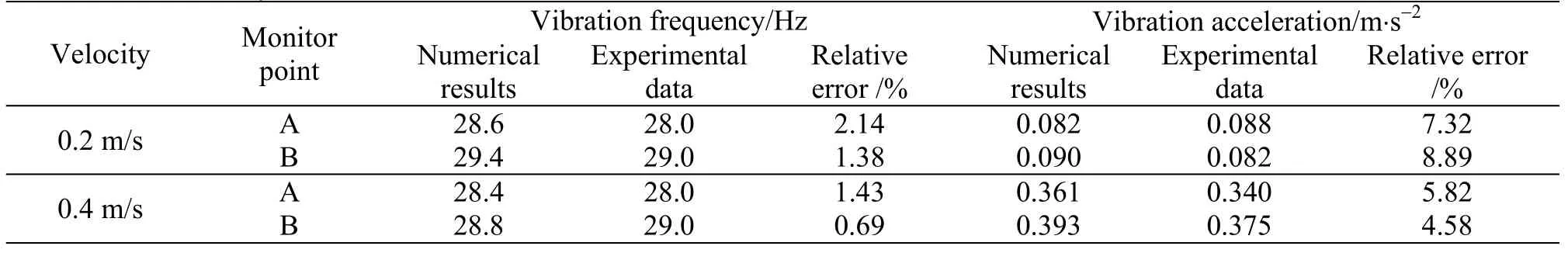
Table 3 Error analysis of numerical results

Fig.5 The spectrogram at the two monitor points (vinlet=0.6 m/s)
Figure 8 shows the flow-induced vibration amplitude of the fundamental frequency against the shell side water inlet velocity. It can be observed from Fig.8 that the vibration amplitude of the fundamental frequency at the two monitor points increases generally with the increase of the shell-side water inlet velocity in all directions. For a certain shell-side water inlet velocity, the vibration amplitude of the fundamental frequency iny-direction orz-direction is higher than that inx-direction. In addition, the peak values of the vibration amplitude can be obtained whenvinlet=1.0 m/s . This is because the flow-induced vibration frequency (23.3 Hz) at such a water inlet velocity is close to the first order natural frequency(23.1 Hz) of the elastic tube bundle.
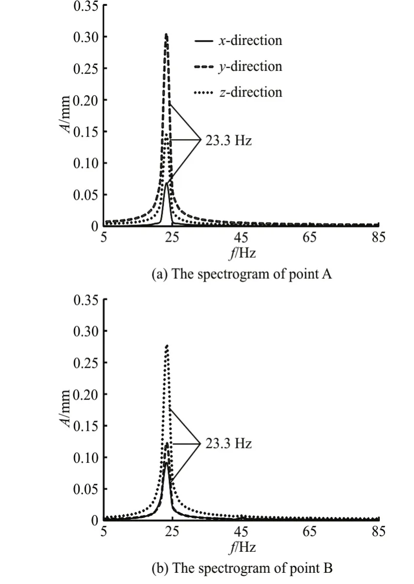
Fig.6 The spectrogram at the two monitor points (vinlet=1.0 m/s)

Fig.7 The vibration frequency against the water inlet velocity
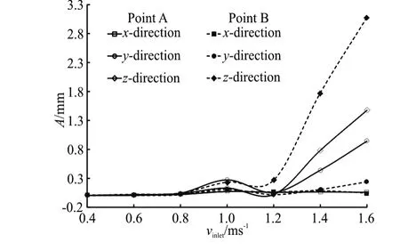
Fig.8 The vibration amplitude against the water inlet velocity
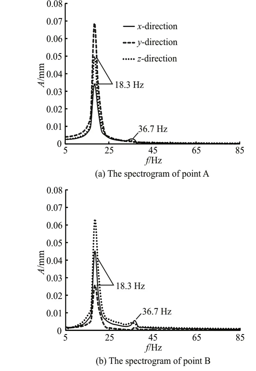
Fig.9 The spectrogram at the two monitor points (δ=1.0 m m)

Fig.11 The vibration amplitude against the tube wall thickness
2.2 Effect of tube wall thickness on vibration responses
Figures 9, 10 show the spectrograms of the flow-induced vibration displacements at the two monitor points (A and B) for different tube wall thicknesses (δ=1.0 mm and 2.0 mm). The numerical simulations are performed at a constant shell-side water inlet velocity (vinlet=0.8m/s)and a constant tube external diameter (r=10.0mm). It can be observed from Figs. 9, 10 that the tube wall thickness has an effect on the vibration amplitude, but no effect on the vibration frequency. The vibration amplitude decreases with the increase of the tube wall thickness.In addition, a harmonic frequency (36.7 Hz) can be observed clearly from Fig.9 and Fig.10 under such numerical simulation conditions.

Fig.10 The spectrograms at the two monitor points (δ=2.0 mm)
Figure 11 shows the flow-induced vibration amplitude of the fundamental frequency against the tube wall thickness of the elastic tube bundle. It can be observed from Fig.11 that the vibration amplitude of the fundamental frequency at the two monitor points decreases with the increase of the tube wall thickness in all directions. On the other hand, the maximum vibration amplitude at the monitor point A appears in they-direction, and the maximum vibration amplitude at the monitor point B appears in thez-direction.
2.3 Effect of tube external diameter on vibration responses
The spectrograms of the flow-induced vibration displacements at the two monitor points (A and B ) for different tube external diameters(r=8.0 mmand 12.0 mm) are shown in Figs. 12, 13. The numerical simulations are carried out at a constant shell-side water inlet velocity (vinlet=0.8m/s)and a constant tube wall thickness (δ=1.5 mm). It can be seen from Figs. 12, 13 that the vibration frequency and amplitude decrease with the increase of the tube external diameter. The vibration amplitude inz-direction at the monitor point B is very clear when the tube external diameter is 8.0 mm. This indicates that the flow-induced vibration of the stainless steel block IV is more intense as compared with that of the stainless steel block III. On the other hand, the harmonic frequency has significant effects on the flow-induced vibration responses when the tube external diameter is 12 mm.

Fig.12 The spectrograms at the two monitor points (r=8.0 mm)
Because the flow-induced vibration fundamental frequencies and the harmonic frequencies at the two monitor points are the same in all directions, we only consider the vibration fundamental frequency of the stainless steel block III inx-direction against the tube external diameter, as shown in Fig.14. It can be observed from Fig.14 that the flow-induced vibration frequency decreases with the increase of the tube external diameter.

Fig.13 The spectrograms at the two monitor points (r=12.0 mm)

Fig.14 The vibration frequency against the tube external diameter
Figure 15 shows the flow-induced vibration amplitude of the fundamental frequency against the tube external diameter of the elastic tube bundle. It can be observed from Fig.15 that the vibration amplitude of the fundamental frequency at the two monitor points decreases generally with the increase of the tube external diameter in all directions. In addition, the maximum vibration amplitude of the stainless steel block III iny-direction can be obtained when the tube external diameter is 9.0 mm, and the maximum vibration amplitude of the stainless steel block IV inz-direction can be obtained when the tube external diameter is 8.0 mm.
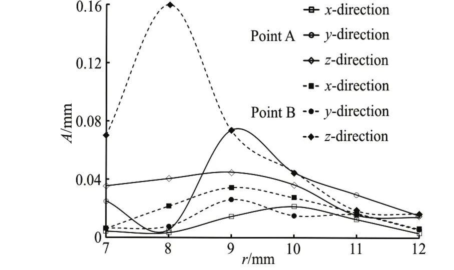
Fig.15 The vibration amplitude against the tube external diameter
2.4 Time history curves of vibration displacement
In order to further investigate the effects of the structural parameters on the responses of the flow induced vibration for the elastic tube bundle, the time history curves of the vibration displacement at the two monitor points are considered in this section. Here, the numerical simulations are performed at a constant shell-side water inlet velocity (vinlet=0.8m/s). Three combinations of the tube external diameter and the tube wall thickness,r=8.0 mm and δ =1.5 mm,r=10.0 mm and δ=1.5 mm ,r=10.0 mm and δ=2.0 mm, are selected.

Fig.16 Time history curves of the vibration displacement (r=8.0 mm,δ=1.5 mm )
Figures 16-18 show the flow-induced vibration displacement at the two monitor points (A and B)against the coupling calculation time for different structural parameter combinations. It can be deduced from Figs. 16-18 that the structural parameters have significant effects on the flow- induced vibration responses. Due to the influence of the shell-side cross flow, the two monitor points vibrate under different structural parameter combinations. On the other hand,the structural parameters affect the vibration frequency and amplitude, and affect the vibration equilibrium position inx-direction. Due to the influence of gravity and the impact force of the shell-side cross flow, the flow-induced vibration at the two monitor points inx-direction has a lower equilibrium position when the elastic tube bundle has a larger wall thickness or a smaller external diameter.

Fig.17 Time history curves of the vibration displacement (r=10.0 mm, δ=1.5 mm)
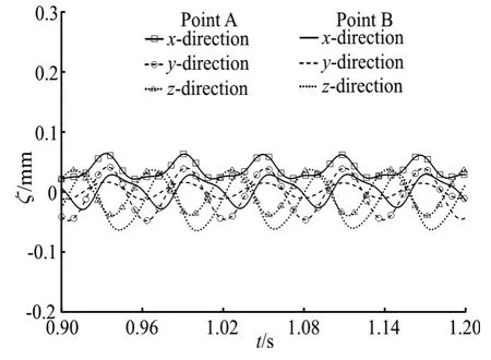
Fig.18 Time history curves of the vibration displacement (r=10.0 mm, δ=2.0 mm)
3. Conclusions
The responses of the flow-induced vibration for elastic tube bundle subjected to the shell-side cross flow are investigated in this paper. The effects of the shell-side fluid flow velocity and the structural parameters on the flow-induced vibration responses are discussed. In order to ensure the accuracy and the reliability of the numerical simulation method, the simulation results are compared with the experimental ones. The main conclusions are as follows:
(1) The vibration frequency and amplitude increase with the increase of the water inlet velocity.The vibration frequencies at the two monitor points at the same water inlet velocity are the same in all directions. For a certain shell-side water inlet velocity,the vibration amplitude of the fundamental frequency iny-direction orz-direction is higher than that inx-direction. In addition, there is a clear harmonic frequency when the water inlet velocity is lower. The fundamental frequencies and the harmonic frequencies at the two monitor points at the same water inlet velocity are the same in all directions.
(2) The tube wall thickness has an effect on the vibration amplitude, but no effect on the vibration frequency. The vibration amplitude of the fundamental frequency at the two monitor points decreases with the increase of the tube wall thickness in all directions. On the other hand, the maximum vibration amplitude at the monitor point A appears in theydirection, and the maximum vibration amplitude at the monitor point B appears in thez-direction.
(3) The vibration frequency and amplitude decrease generally with the increase of the tube external diameter. The vibration amplitude inz-direction at the monitor point B is very clear when the tube external diameter is lower. This indicates that the vibration of the stainless steel block IV is more intense as compared with that of the stainless steel block III. The harmonic frequency has more significant effects on the vibration responses when the tube external diameter is larger.
(4) Due to the influence of the shell-side cross flow, the two monitor points vibrate for different structural parameter combinations. The structural parameters affect the vibration frequency and amplitude,and affect the vibration equilibrium position inxdirection. In addition, the flow-induced vibration at the two monitor points inx-direction has a lower equilibrium position when the elastic tube bundle has a larger wall thickness or smaller external diameter.
Acknowledgement
This work was supported by the Key Projects of Young Teachers Natural Science Foundation of Anhui University of Science and Technology (Grant No.QN201613).
[1] Kumar A., Bhattacharya M. Numerical analysis of aseptic processing of a non-newtonian liquid food in a tubular heat exchanger [J].Chemical Engineering Communications, 2016, 103(1): 27-51.
[2] Huminic G., Huminic A. Experiments on integral and local crystallization fouling resistances in a double-pipe heat exchanger with wire matrix inserts [J].Heat Transfer Engineering, 2016, 37(1): 24-31.
[3] Zamzari F., Mehrez Z., Cafsi A. E. et al. Numerical investigation of entropy generation and heat transfer of pulsating flow in a horizontal channel with an open cavity[J].Journal of Hydrodynamics, 2017, 29(4): 632-646.
[4] Ji J. D., Ge P. Q., Bi W. B. Numerical investigation on the flow and heat transfer performances of horizontal spiral coil pipes [J].Journal of Hydrodynamics, 2016, 28(4):576-584.
[5] Ji J., Ge P., Bi W. Numerical analysis on shell-side flow induced vibration and heat transfer characteristics of elastic tube bundle in heat exchanger [J].Applied Thermal Engineering, 2016, 107: 544-551.
[6] Duan D., Ge P., Bi W. Numerical investigation on heat transfer performance of planar elastic tube bundle by flow-induced vibration in heat exchanger [J].International Journal of Heat and Mass Transfer, 2016, 103: 868-878.
[7] Kim S. H., Ahn B. H., Ha J. M. et al. Structural and vibration analysis considering the flow velocity of the heat exchanger [J].International Journal of Precision Engineering and Manufacturing, 2016, 17(6): 725-732.
[8] Ji J. D., Ge P. Q., Bi W. B. Numerical analysis on shell side flow induced vibration responses of multi-row elastic tube bundles in heat exchanger [J].Journal of Vibration and Shock, 2016, 35(20): 85-89(in Chinese).
[9] Ji J. D., Ge P. Q., Bi W. B. Numerical analysis on combination flow induced vibration responses of elastic tube bundle in heat exchanger [J].Journal of Xi’an Jiaotong University, 2015, 49(9): 24-129(in Chinese).
[10] Ji J. D, Ge P. Q., Bi W. B. Numerical analysis on flow induced vibration responses of elastic tube bundle [J].Journal of Vibration and Shock, 2016, 35(6): 80-84(in Chinese).
[11] Cheng L. Principle and application of elastic tube heat exchanger [M]. Beijing, China: Science Press, 2001(in Chinese).
[12] Cheng L., Luan T., Du W. Heat transfer enhancement by flow-induced vibration in heat exchangers [J].International Journal of Heat and Mass Transfer, 2009, 52(3-4):1053-1057.
[13] Jiang B., Hao W. D., Liu F. G. et al. Experiments on effects of fluid pulsation on heat transfer characteristics of the new type elastic tube bundle [J].Journal of Vibration and Shock, 2012, 31(10): 59-63(in Chinese).
[14] Yan K., Ge P. Q., Hong J. Experimental study of shell side flow-induced vibration of conical spiral tube bundle [J].Journal of Hydrodynamics, 2013, 25(5): 695-701.
[15] Yan K., Ge P. Q., Zhai Q. A comparehensive comparison on vibration and heat transfer of two elastic heat transfer tube bundles [J].Journal of Central South University,2015, 22(1): 377-385.
[16] Su Y. C. A Study on the characteristic of the flow-induced vibration and heat transfer of elastic tube bundle [D].Doctoral Thesis, Jinan, China: Shandong University,2012(in Chinese).
[17] Kimura I., Hosoda T. A non-lineark-ε model with realizability for prediction of flows around bluff bodies [J].International Journal for Numerical in Fluids, 2003, 42(8):813-837.
[18] Xu W. W., Wu D. Z., Wang L. Q. Coupling analysis of fluid-structure interaction in fluid-filled elbow pipe [J].Iop Conference Series: Earth and Environmental Science,2012, 15(6): 1-7.
[19] Zhu H. J., Zhao H. N., Pan Q. et al. Coupling analysis of fluid-structure interaction and flow erosion of gas-solid flow in elbow pipe [J].Advances in Mechanical Engineering, 2014, 2014(7): 1-10.
[20] Tian F. B., Hu D., Luo H. X. et al. Fluid-structure interaction involving large deformations: 3D simulations and applications to biological systems [J].Journal of Computational Physics, 2014, 258(2): 451-469.
猜你喜欢
杂志排行
水动力学研究与进展 B辑的其它文章
- Some notes on numerical simulation and error analyses of the attached turbulent cavitating flow by LES *
- Energy dissipation of slot-type flip buckets *
- Transient aerodynamic characteristics of vans during the accelerated overtaking process *
- Numerical analyses of ventilated cavitation over a 2-D NACA0015 hydrofoil using two turbulence modeling methods *
- Revisit submergence of ice blocks in front of ice cover-an experimental study *
- 2-D eddy resolving simulations of flow past a circular array of cylindrical plant stems *