Energy dissipation of slot-type flip buckets *
2018-05-14JianhuaWu吴建华ShufangLi李书芳FeiMa马飞
Jian-hua Wu (吴建华), Shu-fang Li , (李书芳), Fei Ma (马飞)
1. College of Water Conservancy and Hydro power Engineering, Hohai University, Nanjing 210098, China
2. College of Water Conservancy and Hydro power Engineering, Hebei University of Engineering, Handan 056000, China
The energy dissipation downstream of large dams is a serious concern. The flip buckets are typical elements of chutes or bottom outlets as energy dis sipaters[1-3]. There are many types of the flip buckets used at the end of the release works of Hydro power projects thanks to the suitable hydraulic performance and the effective energy dissipation. According to the outlet shape, we have flip buckets of the constant width-type, the expansion-type, and the contraction type. The constant width outlet is a basic structure,such as the continuous[4,5]or differential[6,7]flip buckets. The expansion[8,9]and contraction flip buckets are mainly used to enlarge the dimension of the flow, either in the flow section or in the flow direction. Thus, the flow speed could be decreased at the jet impact, for the increasing energy dissipation.
Recently, the contraction flip buckets are attracting research attentions, mainly including the flaring gate pier[10,11], the slit-type or multiple slit-type bucket[12-15], and the deflector[16-18]. Those types of contraction flip buckets enjoy remarkable hydraulic characteristics or have a high energy dissipation by decreasing the outlet dimensions.
In the present work, a kind of circular-shaped flip buckets with a slot, called the slot-type flip bucket, is proposed. The bucket has no expansion and contraction of the outlet form, but has a remarkable capability of extending the flow in the flow direction through its slot. This paper theoretically and experimentally investigates the method of estimating the energy dissipation, to establish an estimation expression for the slot-type flip bucket.
The experiments are conducted in the High-speed Flow Laboratory, Hohai University. The experimental setup consists of a pump, an approach conduit, a large feeding basin, a test model, and a flow return system(Fig.1(a)). The feeding basin issues an approach (with subscript o) flow of depthhoand average velocityVo, with the approach flow Froude numberFro=V(gh)0.5. The model discharges are measured withoothe discharge measurement weir instruments. The maximum pump capacityQM=400 L/s, the height differenceS=1.00 m, and the tail water channel widthB=1.00 m. Besides,His the water head to the approach channel bottom,h1andh2are the flow depths before and after the hydraulic jump downstream of the jet impact into the tail water channel, respectively, andV1is the average velocity at the positionh1.
The geometries of the test physical model, made of Perspex, are shown in Fig.1(b). The approach channel widthBo=0.15m , the bucket radiusR=0.50 m, and the deflection angle β=45°.band θ are the width and the angle of the slot, respectively.
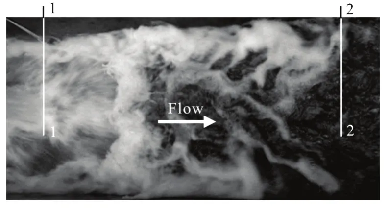
Fig.2 Critical hydraulic jump in tail water channel: Sections 1-1 and 2- 2 as the positions of the sequent flow depths
The energy dissipation of the slot-type flip bucket is defined as η=(Ho-H1)/Ho, withHo=h+S+(V)2/(2g) as the approach flow, andH=oo1h+(V)2/(2g) as the tail water energy head.11
The energy dissipation is estimated on the basis of the hydraulic jump principle. For a critical hydraulic jump beyond the jet impact, by means of adjusting the water level in the tail water channel (see Fig.2), the sequent flow depthh1may be determined through the flow depthh2, and thenV1=Q/(h1⋅B).
The energy dissipation could be directly obtained if the relationship between the flow depthh2and the hydraulic and geometric parameters of the flip buckets is established.
For the flow depthh2, we have
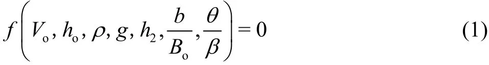
whereb/Boand /θ β are the relative slot width and the relative slot angle of the flip bucket, respectively.On the basis of dimensional analysis, Eq.(1) could be rewritten as
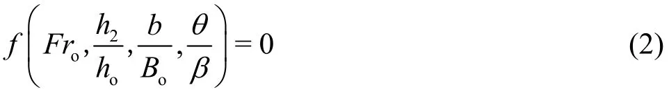
Thus,
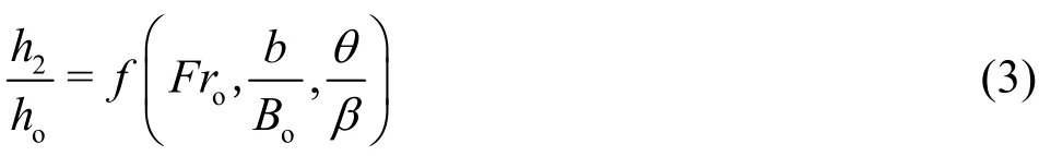
Table 1 lists the cases and the parameters of the slot-type flip bucket models designed according to Eq.(3). The model is the circular-shaped flip bucket whereb=0 or β=45°. The cases M11-M13 are for the changes ofb, and the cases M12-M32 are for the effects of θ. In each case,ho=6.8×10⁻²m,10.5×10-2m and 17.8×10⁻²m, respectively.
Figure 3 shows the jet flows through the slot-type flip buckets at different slot angles (θ) when the model dischargeQ=110 L/s and the approach flow depthho=0.178 m .
In the case M00 (θ=0), the flow jets into the tail water channel as a concentrating flow (Fig.3(a)).In the cases M32-M12, θ=15°, 30° and 45°, respectively. The flows are divided into two parts: the concentrating flow on the top from the two sides of the flip bucket, and the sheet flow of the bottom from the slot of the flip bucket (Figs. 3(b)-3(d)).
It could be noticed that the slot helps the separation of the jet flow, which will have three branches in the left, middle, and right. Especially, the sheet flow increases with the increase of the slot angle. The larger the slot angle, the greater the effect of the separation becomes.
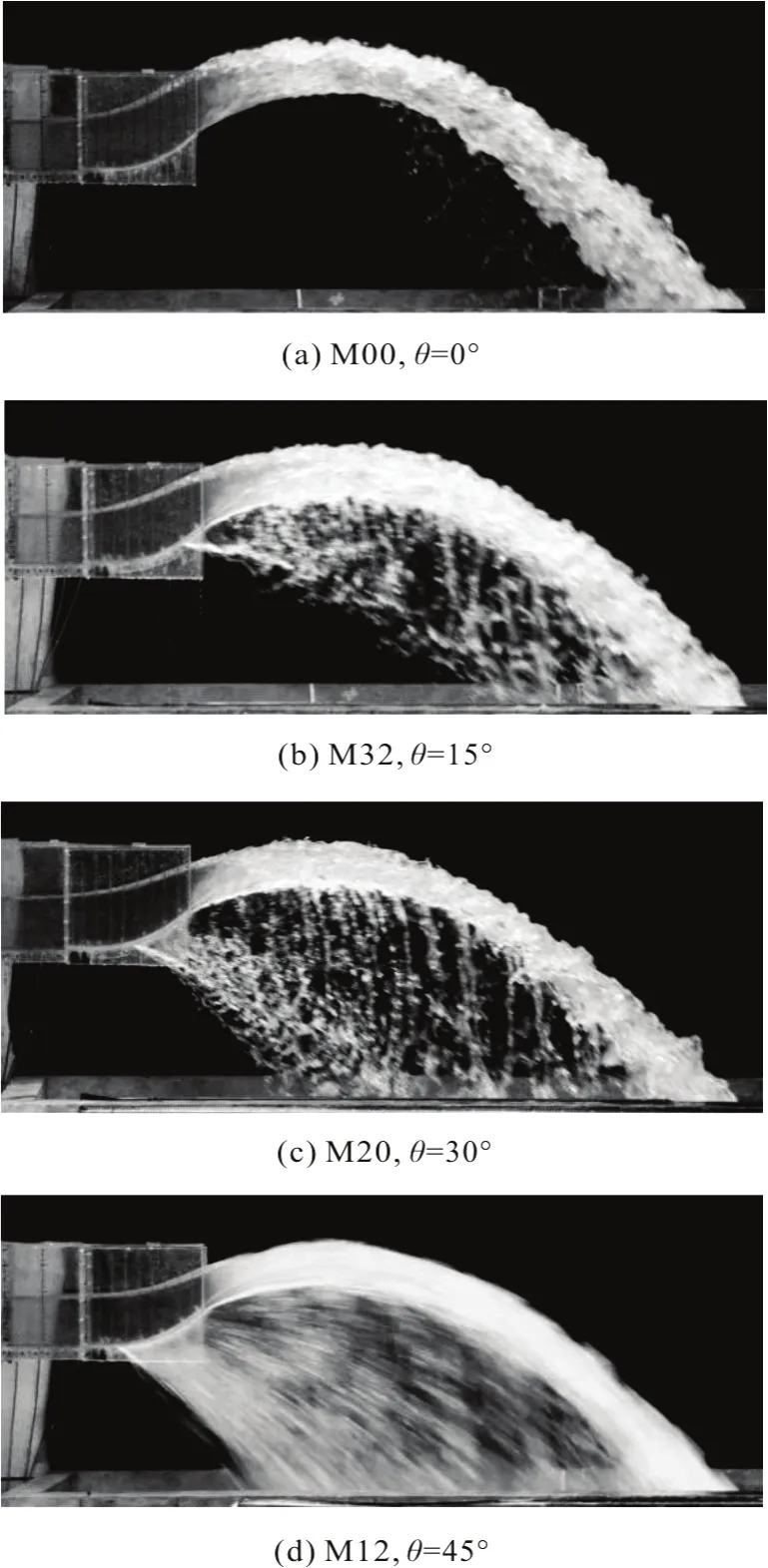
Fig.3 Jet flows of slot-type flip buckets at different slot angles,and model discharge Q=110 L/s
Similar to the extension effect of the flow in the flow direction through contraction-type energy dissipation elements, the slot-type flip bucket can separate the flow into two parts, which will be extended through the slot of the flip bucket in the flow direction.It is well-known that the extension effect increases the energy dissipation of the flow.
Figure 4 is the variation ofh2/howithFro[1-(b/B)2(θ/β)2] according to the experimentaloresults of the different geometric slot-type flip buckets listed in Table 1. We have (R2=0.967)
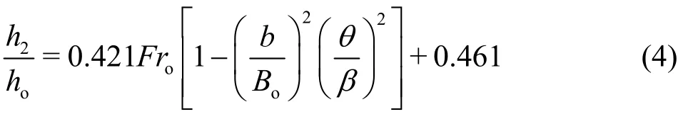
This is the relationship betweenh2/hoand the hydraulic and geometric parameters of the slot-type flip buckets. Thus, we can obtainh1andV1, and then ηby means ofh2/ho.

Fig.4 Variation of h2/ ho with Fro [1 -(b/ B o )2 (θ/ β)2]for different geometric slot-type flip buckets
Given η throughh2/ho, Fig.5 shows the variation of ηwith (h2/ho)[0.2 +(b/Bo)(θ/β)]for different geometric slot-type flip buckets. The best fit is (R2=0.941)
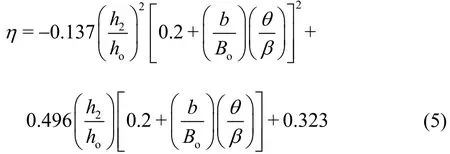
Eqs. (4) and (5) are valid forb/Bo=0-0.5, θ/β=0-1.0, andFro< 6.1. In the cases M00 and M13 whenFro=6.0, we have η=57.0% and 76.8%,respectively, on basis of Eqs. (4) and (5). It could be seen that the slot of the flip buckets has a remarkable effect on η. Both largeb/Boand large θ/ β of the flip buckets produce a high η in the ranges of the present study.

Fig.5 Variation of η with (h 2 / ho )[0.2 +(b/ Bo )(θ/ β)]for different geometric slot-type flip buckets
In short, for the slot-type flip buckets, a method of estimating the energy dissipation is proposed in this paper. The theoretical analysis shows that, in order to determine the energy dissipation, it is necessary to determineh1andV1throughh2andh2/hois a function ofFro,b/Boand θ/ β. The expression ofηis developed with the maximum error of not larger than 9.21% on the basis of error analysis.
[1] Novak P., Moffat A. I. B., Nalluri C. et al. Hydraulic structures [M]. 3rd edition, London, UK: Taylor and Francis, 2001.
[2] Vischer D. L., Hager W. H. Dam hydraulics [M].Chichester, UK: Wiley, 1998.
[3] Khatsuria R. M. Hydraulics of spillways and energy dissipators [M]. New York, USA: Dekker, 2005.
[4] Schmocker L., Pfister M., Hager W. H. et al. Aeration characteristics of ski jump jets [J].Journal of Hydraulic Engineering, ASCE, 2008, 134(1): 90-97.
[5] Heller V., Hager W. H., MINOR H. E. Ski jump hydraulics [J].Journal of Hydraulic Engineering, ASCE, 2005,131(5): 347-355.
[6] Yang S. L. Dispersive-flow energy dissipater [J].Journal of Hydraulic Engineering, ASCE, 1994, 120(12):1401-1408.
[7] LIU S. H. High speed flow [M]. Beijing, China: Science Press, 2005(in Chinese).
[8] Zhu Y. Q., Zhang F. X., Xu W. L. Research on hydraulic characteristics of flip bucket with tongue-type [J].Science Technology and Engineering, 2004, 4(5): 397-403(in Chinese).
[9] Xue H. C., Diao M. J., Yue S. B. et al. 3-D numerical simulation of the jet nappe in the beveled flip bucket of the spillway [J].Chinese Journal of Hydraulic Research,2013, 44(6): 703-709(in Chinese).
[10] Li N. W., Liu C., Deng J. et al. Theoretical and experimental studies of the flaring gate pier on the surface spillway in a high arch dam [J].Journal of Hydrodynamics, 2012, 24(4): 496-505.
[11] Qiu C., Liu C. L. 3D Dynamic numerical simulation of water flow in stilling basin with flaring gate pier [J].Applied Mechanics and Materials, 2014,580-583:1971-1974.
[12] Liu S. H., Duan H. D. Simulation of the atomized flow by slit type bucket energy dissipater [J].Journal of Hydrodynamics, 2005, 17(6): 758-763.
[13] Ma F., Xu Z., Wu J. H. Flow choking over weir flow slittype flip buckets [J].Journal of Hydrodynamics, 2015,27(6): 907-912.
[14] Wu J. H., Yao L., Ma F. Hydraulics of a multiple slit-type energy dissipater [J].Journal of Hydrodynamics, 2014,26(1): 86-93.
[15] Wang G. B., Hu H., Wang C. H. et al. Shock waves and water wing in slit-type energy dissipaters [J].Journal of Hydrodynamics, 2017, 29(3): 504-509.
[16] Lucas J., Hager W. H., Boes F. M. Deflector effect on chute flow [J].Journal of Hydraulic Engineering, ASCE,2013, 139(4): 444-449.
[17] Jadhav R. C., Deolalikar P. B. Design of spillway energy dissipater in the form of a ski-jump bucket with a wedge-A case study [J].ISH Journal of Hydraulic Engineering, 2000, 6(1): 12-19.
[18] Juon R., Hager W. H. Flip bucket without and with deflectors [J].Journal of Hydraulic Engineering, ASCE,2000, 126(11): 837-845.
猜你喜欢
杂志排行
水动力学研究与进展 B辑的其它文章
- Some notes on numerical simulation and error analyses of the attached turbulent cavitating flow by LES *
- Transient aerodynamic characteristics of vans during the accelerated overtaking process *
- Numerical analyses of ventilated cavitation over a 2-D NACA0015 hydrofoil using two turbulence modeling methods *
- Revisit submergence of ice blocks in front of ice cover-an experimental study *
- 2-D eddy resolving simulations of flow past a circular array of cylindrical plant stems *
- Couple stress fluid flow in a rotating channel with peristalsis *