Navigation Route Based Stable Clustering for Vehicular Ad Hoc Networks
2018-04-04ZhiweiYangWeigangWuYishunChenXiaolaLinXiangChen
Zhiwei Yang, Weigang Wu, Yishun Chen, Xiaola Lin, Xiang Chen,2,*
1 School of Data and Computer Science, and School of Electronics and Information Technology,Sun Yat-sen Univ., Guangzhou, 510006 China
2 Key Lab of EDA, Research Institute of Tsinghua University in Shenzhen (RITS), Shenzhen 518075, China
* The corresponding author, email: chenxiang@mail.sysu.edu.cn
I. INTRODUCTION
Vehicular Ad hoc NETwork (VANET) [1]enables vehicles to communicate with Roadside Unit (V2R) or other vehicles (V2V) via wireless communications. VANETs can help drivers to acquire real time information about traffic status. Applications of VANETs range from driving support services, such as content distribution [2], route selection [3] and Internet access [4]. In this paper, we aim to realize a cost-effective V2V system for information dissemination [5].
One of the major challenges in VANETs is the rapid change of network topology due to high mobility of vehicles. Actually, topology changes will introduce high communication overhead for exchanging new topology information. Establishing a cluster based hierarchy[6], [7] is an effective and popular approach to cope with topology dynamics in ad hoc networks, including VANETs. Vehicles are grouped into clusters, each with a clusterhead node that is responsible for all management and coordination tasks of its cluster. Node clustering allows the formation of dynamic virtual backbone and can be used to support medium access control [8], [9], packet routing [10], broadcasting [11], and other network services [6].
On the other hand, node clustering in VANETs is not a trivial task due to the high dynamics of vehicle mobility. Therefore,improving the stability of clusters has been always a major concern of clustering algorithms for VANETs [12], [13], [14]. Namely,an efficient clustering algorithm for VANETs should keep the cluster structure unchanged as long as possible, so as to reduce the overhead of clustering [15].
Many algorithms have been proposed for VANET clustering in recent years, which usually improve cluster stability by taking account of position, speed, and distance data of vehicles. Some recent works consider the lanes of vehicles and the effect of intersections.
In this paper, we consider to improve the stability of clusters by making use of navigation route information. Nowadays, vehicular navigation systems based on GPS or alternative techniques have been equipped with nearly all cars on roads. The route of a vehicle can be planned in advance by the navigation system. Such a route obviously indicates the future movement path of the corresponding vehicle [16], [17]. To improve the stability of clusters, vehicles with similar routes should be grouped into one cluster.
However, making use of navigation route in clustering is not a trivial task. A route should consist of several road segments, each of which usually suggests a turn along the road network. More importantly, the route information must be converted into a value of time so as to reflect the stability requirement. Therefore, how to compare the routes of different vehicles and calculate their overlapping time is necessary but not easy. Also, the cost of route information exchange must be considered seriously. Different from simple data like position and speed, route data is more complex. Although the route of a vehicle may not change frequently, vehicles need to exchange such information with respect to cluster changes. The overhead of route data exchange may require much wireless communication resources.
In this paper, we propose a novel clustering algorithm based on the information of route planned by vehicular navigation systems. In particular, the main contributions of this paper are outlined as follows.
We design a residual route time function,which quantitatively calculates the time interval during which two vehicles may keep to be neighbors. With this function, we propose a metric to evaluate the priority of leadership(being clusterhead). The metric also includes the number of neighbors as input, so as to guarantee the effectiveness of the cluster structure in terms of topology control.
To reduce the cost of cluster maintenance,we further design a mechanism of future-clusterhead. The split and merging of clusters are common, especially at intersections. Vehicles need to exchange their route data upon such cluster changes. Considering that some nodes1In this paper, the terms“node” and “vehicle” are used interchangeably.in a new cluster may previously come from the same old cluster and have known routes of each other, we let only one of them exchange route data with nodes from other clusters for possible merging. Such a vehicle is called a future-clusterhead. Future-clusterheads are also elected based on route information collected during cluster forming.
To examine the performance of our route based clustering algorithm, we conduct simulations using ns-3. The vehicle mobility data are generated by SUMO. For comparison purpose, we also simulate three representative VANET clustering algorithms. The results show that, our navigation route based clustering algorithm can achieve higher stability and at the same time reduce communication cost.
The rest of the paper is organized as follows. Existing clustering algorithms for VANETs are brie fly reviewed in the following section. Section III presents the system model and assumptions involved in our design. The proposed clustering algorithm is presented in Section IV, with detailed description of metric de finition and calculation, cluster forming operations, and cluster maintenance operations.In this section, we also discuss possible issues that may arise from implementing our algorithm. Performance evaluation is reported in Section V and finally Section VI concludes the paper with future directions.
II. RELATED WORKS
2.1 Clustering in VANETs
There are quite a number of clustering algorithms designed for VANETs. Since clusterhead election is usually the core part of clustering, we review existing algorithms according to the leadership metrics used for selecting In this paper, we propose a novel clustering algorithm based on the information of routes planned by vehicular navigation systems.clusterheads.
Most algorithms adopt leadership metrics based on (relative) speed and distance.Basically, the relative speed and/or distance between neighboring vehicles are calculated and the node with the minimum difference with its neighbors will be elected as a clusterhead. These algorithms mainly differ in the procedure of clustering vehicles. The SP-Clustering algorithm [18] is a typical example of this category, where the relative speed is calculated by the change of distance. More precisely, the distance between two vehicles is calculated using the signal strength of hello messages. Based on distance change, the algorithm can determine whether two nodes are closing to each other, and then delay cluster re-organization if possible. Hafeez et al. [19]adopt fuzzy logic based learning mechanism for predicting the future speed and position of cluster members so as to reduce the cost of cluster maintenance. The algorithm in [12]elects a secondary clusterhead for each cluster to improve the reliability of clusterhead. The af finity propagation (AP) algorithm [20],[21]is a distance based clustering algorithm, which requires a lot of iterative loops that increase the delay time of cluster construction.
Ucar et al. [22] focus on a multi-hop clustering algorithm. The clustering algorithm considers the relative mobility metric calculated as the average relative speed with respect to the neighboring vehicles. It provides cluster connection with minimum overhead by introducing direct connection to the neighbor that is already a head or member of a cluster.
Another type of leadership metric is based on connection/link duration time. A vehicle needs to estimate the duration of the links with its neighbors and such a value is used to evaluate the priority of being clusterhead. The algorithms in [11], [23] choose the node with the longest connection duration as the clusterhead,while the MA-Clustering algorithm in [24]takes the distance to destination points into consideration. The MA-Clustering algorithm takes the destination of vehicles into account,including the current location, speed, relative destination and final destination of vehicles, as parameters to arrange the clusters. The metric for clusterhead selection is the weighted sum of three parts: current distance of two vehicles,current speed difference of two vehicles and distance between their destination points.
An approach to select the clusterhead(CH)by considering the location, velocity and the equipment of the vehicles is proposed in [25].The clustering algorithm in [26] considers the minimum probability to move out of the cluster and the maximum efficiency of intra-cluster communications. The proposed distributed clustering architecture creates a dynamic virtual backbone in the network, formed by clusterheads and cluster-gateways. Wang et al. [27] integrates MAC protocol operations,PHY layer wireless channel conditions, and the moving pattern of the vehicles for clustering. A Markov Chain model is used for an unsaturated VANET cluster.
In [28], link duration is integrated with node criticality, a graph notion that quanti fies the robustness of the graph against environmental changes such as topology.
The algorithms in [14], [29] take the lane information into consideration in clusterhead election. In [29], a lane weight is assigned for each traffic flow, i.e., left turn, right turn and no turn, and the weight is integrated with the common metric of speed and distance. The algorithm in [14] also clusters vehicles according to the lanes of vehicles, but it assumes the knowledge of direction at the next intersection.
Geographic position based clustering is reported in [3], where clusters are firstly constructed based on the geographic position of vehicles and then clusterhead of each cluster is elected among all nodes in the cluster. A hash function based on the estimated travel time is used to generate this priority for the vehicle.
From the review of existing VANET clustering algorithms we can conclude that, various metrics have been proposed and used to select clusterheads and construct clusters in VANETs, but navigation route has not been considered. This motivates us to design the novel algorithm in this paper.
2.2 Navigation route based data forwarding in VANETs
Although navigation route has not been considered in clustering algorithms, it has been used in selecting data forwarding nodes in[30], where the term “trajectory” rather than“route” is adopted.
In the Trajectory-Based Data Forwarding(TBD) algorithm [17], navigation route of a vehicle is combined with traffic statistics to improve the performance of data forwarding in road network. However, TBD uses navigation route information in a privacy preserving way, i.e. the individual vehicle only acquires its own trajectory and does not share route information with other vehicles.
Li et al. [31] propose a network coding with crowd sourcing based trajectory estimation method to transmit data in vehicular networks.The estimation is completed by every node based on the pre-trajectory of GPS navigation.Network coding is used for data transmission according to the result of trajectory estimation.
The Shared-Trajectory-based Data Forwarding Scheme (STDFS) algorithm proposed in [32] makes use of route information in a shared way. Such information is used to predict the encounters between vehicles, and a predicted encounter graph is constructed accordingly. Based on the encounter graph,STDFS optimizes the forwarding sequence to minimize delivery delay under a specific delivery ratio threshold.
The Trajectory for Multicast (TMC) algorithm in [16] considers navigation route based multicasting. Route information is used to predict the chance of inter-vehicle encounter between two vehicles, and then the prediction result is further used to characterize the capability of a vehicle to forward a given message to destination nodes.
In our work, we also use navigation route information in a shared way, as in [16], [32].However, we work on the clustering problem,which is quite different from the problem of direct selection of forwarding nodes. Moreover, we consider overlapping segments in navigation routes, while existing algorithms focus on the encounter probability of vehicles in opposite or crossing directions.
III. SYSTEM MODEL AND ASSUMPTION
In this paper, we focus on the issue of construction and maintenance of clusters for information dissemination in VANETs. Each participating vehicle is equipped with a navigation system and a V2V communication device. The system can provide position information (via GPS) and speed of the vehicle. Each vehicle has a prede fined start location and destination location. The route of a vehicle is planned by the navigation system. A route should be set at the starting and may be dynamically changed on the way according to traf fic conditions, but such changes should be infrequent.
The network is divided into road segments according the real road network. The route of a vehicle is a sequence of road segments and turn directions (turn left, turn right, no turn) at intersection between two adjacent segments. In each route, there is no repeated segment, and also no loops. For the simplicity of presentation, we assume that, an intersection is simply the cross of two roads. The traffic light is placed at the intersection to control the passing of vehicles.Intersections of other types, i.e. crossing of more roads, can be handled similarly.
Each vehicle is also equipped with a wireless communication device. Two vehicles are connected in ad hoc way. The wireless link is assumed to be reliable and no packets will be lost (message loss can be handled by retransmissions in networking protocols.). Two vehicles within transmission range of each other can communicate directly and they are neighbors of each other. The transmission range is less than the length of a road segment. Heartbeat messages are periodically exchanged among neighbors to probe neighbors, so each vehicle knows its neighbors and maintain a neighbor list. A heartbeat message also carries the speed and position information.
The route of a vehicle consists of a sequence of road segments, and each segment can be represented by the corresponding intersection ID (or number) and direction to go. Such information is with small size, so it can also be included into the heartbeat messages when it is necessary. On the other hand, if the route information is too large to be integrated into heartbeat message, vehicles can exchange route information via special messages. Since navigation route of a vehicle is seldom changed after selected, exchange of route information can be done with a much longer period than heartbeat,and the overhead of route information exchange would be suf ficiently reduced.
IV. THE PROPOSED ALGORITHM
Same as most existing clustering algorithms,our proposed algorithm consists of two phases:cluster formation and cluster maintenance.However, our algorithm has an additional mechanism of future-cluster. Future-clusters are formed in the cluster formation phase and used in cluster maintenance phase to save communication cost.
In the formation phase, vehicles firstly exchange mobility information, including position, speed and direction, and route information, with neighbors via heartbeat messages.Then, each vehicle calculates the priority of being clusterhead according to the metric of residual route time (RRT). When clusterheads are elected, common vehicles will join the clusters correspondingly. Future-clusters are formed by a clusterhead, according to the vehicles’ directions at the next intersection.

Fig. 1. The finite state machine of our algorithm.
In the following, we firstly present the definition and calculation of RRT, and then describe operations of cluster formation,future-cluster formation and cluster maintenance. Finally, we discuss some issues that may arise from the implementation of our algorithm.
To help understand our algorithm, we provide the state machine of node status switch in figure 1. The status of a node may be:
· Undecided state (UN): the node is not in any cluster.
· Clusterhead (CH): the node is a clusterhead.
· Cluster member (CM): the node is a member of some cluster , but not a clusterhead.
· Future-clusterhead (FCH): the node is a future-clusterhead, which is in charge of coordinating the merge of clusters.
4.1 The metric of residual route time
RRT is the metric to evaluate the priority of leadership in terms of cluster stability. The basic idea is that, among a group of vehicles being neighbors of each other, the one who stays in the group for the longest time should be the leader.However, before clusters are constructed, no such “group” can be known and used. Then, how to define a metric to measure the leadership of vehicles with respect to the stability?
In our design, we de fine RRT, which is the representation of the “overall” time duration of neighborhood between a vehicle and its current neighbors. With route data of neighbors, a vehicle can carry out such estimation. Table 1 lists the notations used in the de finition of RRT.
For a pair of neighbor nodes i and j, we can estimate tij, the time they will keep to be neighbor in future trip:

The calculation of tijconsists of two parts.The first part is the short term estimation,which estimates the time that two vehicles will keep to be neighbors in the current road segment. It can be calculated using current speed and position information. A positive value indicates that two vehicles are becoming closer to each other, while a negative value indicates that two vehicles are leaving each other. The current speed of vehicles can be the average value obtained via the navigation system. Of course, an estimation value based on average speed obtained from historic value may also be acceptable.
The second part is the long term estimation,which is the time that two vehicles may be neighbors of each other in the future overlapping road segments. Since the vehicles haven’t entered these segments yet, such a time duration can only be calculated based on the expected speed obtained from historical data vik. In fact, more and more vehicle navigation systems provide real time road traf fic state information, especially expected moving speed at different roads, and such speed data can be adopted as value of vk. Moreover, two neighbor nodes may be disconnected future in overlapping roads due to traf fic light scheduling at intersections or too large speed difference. We introduce the parameter pijkto denote the probability that two neighboring nodes become disconnected at road k. Such a value can be obtained by historic data analysis.
Then, considering all neighbor nodes of i,we have the total time of neighborhood:

Beside the time of neighborhood, we notice that the number of neighbor nodes is also a key factor that may affect the efficiency of a cluster structure. For a 1-hop cluster, more neighbors will result in more communication cost which can be saved in upper layer applications. Therefore, we add a parameter related to number of neighbors in the final value of residual route time RRT, i.e.:

where

The parameter θ is used to include the effect of the number of neighbors, or topological centrality of a node. Roughly, a node withmore neighbors should have a higher priority to be a clusterhead than others, because it can forward information to more nodes in one sending and consequently reduce the cost of communication. The parameter θ is introduced exactly to realize such an idea.
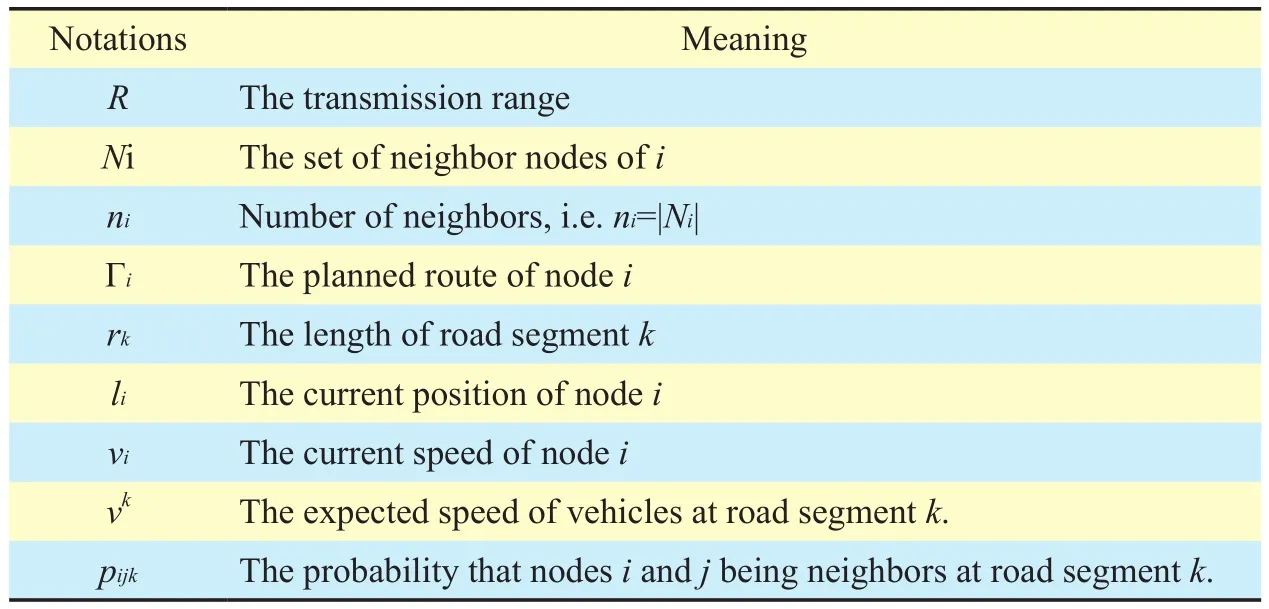
Table I. Notations used
Finally, we have the complete de finition of RRT:

The above calculation of RRT focuses on the effect of vehicle movement, and the quality of wireless link between neighboring nodes is assume to be perfect, which may not be a practical assumption. The effect of channel quality is discussed later in Section IV-F.
4.2 Message types
The following messages may be used in our clustering algorithm.
· HELLO: the heartbeat message broadcasted by each node to exchange information of speed and location, the RRT value, the route data, node status, and the number of neighbors.
· JOIN(CHid,UNid): the message for an uncertain node UNidto request to join a cluster CHid.
· ACK(CHid,UNid) : the message for a clusterhead CHidto accept the join request from an uncertain node UNid.
· FCH(fch_list, fch_fcm_list): the message for a clusterhead to announce future-cluster formation result to cluster members. It carries the list of future-clusterheads fch_list,and the corresponding members of each future clusterhead fch_fcm_list.
· QUERY(CHid,FCHid, fcm_list): the message for a future-clusterhead FCHidto request to join a cluster CHid. It carries the member list of the future-cluster fcm_list.
· RESPONSE(CHid,FCHid) : the message for a clusterhead CHid,to accept the join request of a future-clusterhead FCHid.
4.3 Cluster formation
The pseudo code of cluster formation is shown in algorithm 1.
The procedure of the cluster formation phase in our algorithm is similar to most existing algorithms, except that our new metric is used to evaluate the priority of being clusterhead. Initially, there are no clusters and all the vehicles are in undecided (UN) state.

Algorithm 1. Cluster Formation On Uncertain State of node i :Input: Neighbor Information List Nnb Output: node state 1 Get CH neighbor list NCH from Nnb 2 Remove neighbors without overlapping route 3 Calculate RRTMax based on NCH 4 if RRTMax > RRTi then 5 send JOIN(CHid,UNid) to clusterhead with RRTMax 6 if ACK(CHid, UNid) is received then 7 switch to CM state 8 end if 9 else 10 calculate UN neighbor list NUN based on Nnb 11 calculate CH election list (excluding those without overlapping route: ch_election_list← NUN ∩ Noverlapping)12 calculate RRTMax from ch_election_list 13 if RRTi > RRTMax then 14 switch to CH state 15 end if 16 end if 17 if state is UN then 18 Schedule next round of cluster formation 19 else 20 stop 21 end if
The clustering algorithm is initiated by the upper layer application or other mechanisms.The first step is exchanging HELLO messages with its neighbors to collect information used in the calculation of RRT. More precisely, the HELLO message contains neighbor number and route data. Notice that in the beginning,the nodes do not know their neighbors and the neighbor number in the HELLO message is set to be zero. Later, the number of neighbors is changed according to the HELLO messages from neighbors.
Upon receiving HELLO messages from neighbors, a vehicle i will calculate its RRT accordingly, and then includes its RRT value into its HELLO message. To adapt the dynamic changes of network topology and navigation route, RRT value is updated upon the detection of such changes. Obviously, i will receive HELLO messages containing RRT value from its neighbors in the third and later rounds.
In the initial state, each node is in the UN state, so there is no clusterhead in the neighbor list of any node. When an UN node detects no clusterhead in its neighborhood, it will start the clusterhead election procedure. It will firstly include all UN neighbors into a CH election list, excluding those without sharing/overlapping navigation road segments. Notice that the CH election list contains only UN nodes,and a non-UN node will not be included, even though it has a greater RRT. If vehicle i has a greater RRT value than all its neighbors in the CH election list, i itself is selected as a clusterhead by switching to the CH.
In later rounds, when one or more HELLO messages from clusterhead are received, i will choose to join the cluster with the highest RRT value by sending a JOIN(CHid,UNid) message.The corresponding clusterhead will send an ACK(CHid,UNid) message to con firm the join.Vehicle i then switches to be in the CM state.
On the other hand, if the UN node i does not receive HELLO message from its clusterhead (all neighbors with higher RRT join clusters of other vehicles), i will wait for more rounds until a suitable CH is found or it has the greatest RRT among all the UN neighbors.
Since at each round, at least one UN node changes its status to CH or CM, eventually each UN node will decide its status and the cluster formation procedure stops.
4.4 Formulation of future-cluster
The vehicles in one cluster may turn to different directions at the next intersection. Accordingly, we divide one cluster into multiple future-clusters, each of which contains vehicles that will turn to the same direction. Then, after passing the intersection, vehicles in the same future-cluster can simply form a new cluster,even without exchanging node status information. This can help reduce the overhead of cluster maintenance, in terms of both message and time. The pseudo code of constructing future clusters is shown in algorithm 2.
Since each cluster is coordinated and managed by its clusterhead, the formation of future-clusters is also conducted by clusterhead.After a cluster is formed, the clusterhead must have collected route data from all members.
The future cluster formation is triggered each time the clusterhead detects that it has entered a new road. By checking the route of cluster members, the clusterhead can divide them into future-clusters according to their direction at the next intersection. At a typical intersection with two roads cross with each other (other intersection scenarios can be handled similarly), vehicles will take one of three directions: LT (left turn), RT (right turn) or NT(no turn). Then, at most three future-clusters may be formed within one cluster.
Accordingly, the clusterhead can compare RRT values of all members and assign the vehicle with the largest RRT in a future-cluster to be the future-clusterhead. To keep stable,the clusterhead will choose itself as the future-clusterhead of its own future-cluster. After the clusterhead of a cluster determines future-clusters and assigns future-clusterhead, it will broadcast the results to all members, via a FCH(fch_list,fch_fcm_list) message. And each member will learn about its own future-cluster and future-clusterhead.
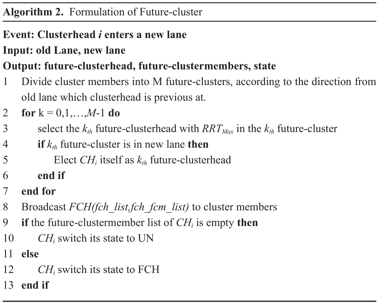
Algorithm 2. Formulation of Future-cluster Event: Clusterhead i enters a new lane Input: old Lane, new lane Output: future-clusterhead, future-clustermembers, state 1 Divide cluster members into M future-clusters, according to the direction from old lane which clusterhead is previous at.2 for k = 0,1,…,M-1 do 3 select the kth future-clusterhead with RRTMax in the kth future-cluster 4 if kth future-cluster is in new lane then 5 Elect CHi itself as kth future-clusterhead 6 end if 7 end for 8 Broadcast FCH(fch_list,fch_fcm_list) to cluster members 9 if the future-clustermember list of CHi is empty then 10 CHi switch its state to UN 11 else 12 CHi switch its state to FCH 13 end if
Notice that a node assigned to be future-clusterhead will not start the cluster merging procedure until it passes the corresponding intersection. On the other hand, the cluster member maintenance mechanism of a future-cluster, which is similar to the maintenance mechanism of a cluster, will begin immediately after the future-clusterhead is assigned.
4.5 Cluster maintenance
After clusters are formed, the cluster members and clusterhead of a cluster monitor each other via HELLO messages. The HELLO message of a cluster member is different from common HELLO messages. It contains the ID of the cluster it belongs to, which may be in fact the ID of the clusterhead.When a cluster member is disconnected from its clusterhead due to speed difference or turning at intersections, it needs switch to another cluster. On the other hand, a new clusterhead may be selected due to split and merging at intersections. Moreover,a cluster should be destroyed if there are too few members or a clusterhead with higher RRT value is in the neighborhood. Such cases are handled by the cluster maintenance mechanism.Cluster switch.
When a cluster member idetects disconnection from its current clusterhead, it will switch to UN state, and try to switch to some cluster with the clusterhead that is currently in neighbor list by sending a JOIN(CHid,UNid) message. The following operations are the same as in the cluster formation procedure. When the target clusterhead j receives the the JOIN(CHid,UNid) message,it will reply with an ACK(CHid,UNid)message and correspondingly i becomes a new member of cluster j.
?
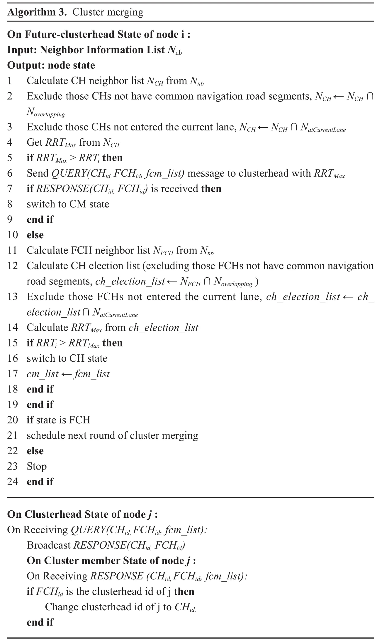
Cluster merging. The case of cluster change at intersection is more complex. After passing an intersection, one cluster will be split into three or less future-clusters. Once a future-clusterhead passes the intersection, it will starts the procedure of cluster merging with other cluster/future-clusters that enter the same lane.
The future-clusterhead will firstly try to merge with other clusters. It will prepare the candidate clusterhead list by adding the clusterhead neighbors and excluding those without overlapping route and those not entered the current lane yet. Then, the future-clusterhead will select the node with the greatest RRT, say CHid, from candidate clusterhead list, and send a QUERY(CHid,FCHid, fcm_list) message to CHid, which carries future-clusterhead id and future-cluster member list. Upon receiving a QUERY(CHid,FCHid, fcm_list) message, the clusterhead will reply by broadcasting RESPONSE(CHid,FCHid). Corresponding to the RESPONSE(CHid,FCHid), a cluster member can join the clusterhead CHid,along with future-clusterhead FCHid. Notice that, we let only clusterhead respond to a query, so as to reduce message cost.
On the other hand, if no clusterhead is in the candidate clusterhead list, clusterhead re-election is unavoidable. To reduce role changes and simplify operations, clusterhead re-election is done among only future-clusterheads. More precisely, the future-clusterhead will compare its RRT value with other neighboring future-clusterheads. The future-clusterhead with the greatest RRT is then elected as the new clusterhead, and other future-clusterheads will join the new cluster together with their members, as described previously.
The pseudo code of cluster merging is shown in algorithm 3.
Cluster destruction. A cluster may be destroyed if there are too few members. The pseudo code of destructing a cluster is shown in algorithm 4. A clusterhead keeps monitoring its members and neighbor RRT value via HELLO messages. If the number of members decreases and becomes less than a predefined threshold for a time long enough, the clusterhead will destroy the cluster by switching to be a future-clusterhead and try to join another cluster.The rest operations are the same as cluster merging.
4.6 Channel quality and packet loss
In the description above, for the purpose of easy understanding, we focus on the clustering operations and do not consider the quality of communication channels. However, wireless channels are vulnerable to various effects, including interference, obstacles, etc.
Our clustering algorithm may handle wireless channel quality in two directions. Firstly,the quality of a wireless link between two nodes can be included in the evaluation of RRT. That is, channel quality can be used as a coefficient in the equation calculating overlapping time of two nodes. Secondly, messages may be lost due to poor channel quality. This can be handled by re-sending messages when it is necessary. In fact, even if some messages cannot be received finally, our algorithm can still run normally and the only price to pay is the deduction in efficiency.
4.7 Algorithm analysis
We analyze the performance of the proposed algorithms in terms of time cost and communication cost.
Roughly, the time cost of the cluster formation algorithm is O(n), where n is the number of the vehicles in the network. While the communication cost of cluster formation algorithm is O(nk), where k is the sum of the massage size of HELLO, JOIN and ACK.
When passing an intersection, one cluster will be split into three or less future-clusters.Thus, in the proposed algorithm, the number of the re-clustering vehicles is at most O(3w)at each intersection, where w is the number of the clusters at relevant intersection. Obviously, our algorithm can signi ficantly reduce the re-clustering overhead at road intersections.
V. PERFORMANCE EVALUATION

Algorithm 4. Cluster destruction On clusterhead State of node i :Input: cm_list, expire time Output: node state, expire Time, fcm_list 1. if size of cm_list > thresholdCH 2. expire Time ← Update( expire time)3. end if 4. if expire time < time now then 5. switch to FCH state 6. fcm_list ← cm_list 7. end i On future-clusterhead State of node j :Input: fcm_list, expire time Output: node state, expire Time 1. if size of fcm_list > thresholdFCH 2. expire Time ← Update( expire time)3. end if 4. if expire time < time now then 5. switch to UN state 6. end if
To evaluate the performance of our algorithm,we conduct simulations using ns-3. The mobility of vehicles is simulated via SUMO, a widely used tool to simulate vehicle mobility that can be integrated with ns-3.
To accurately examine the effect of our proposed future-clusterhead mechanism, we simulate our algorithm under two different variants: RT-Clustering is the variant without future-clsuterhead and RTF-Clustering is the variant with the future-clusterhead mechanism.
For comparison purpose, we also simulate three representative existing algorithms:ID-Clustering [33], SP-Clustering [18],and MA-Clustering [24]. We choose these three algorithms because, SP-Clustering and MA-Clustering should be the best among existing VANET clustering algorithms in terms of cluster stability, while ID-Clustering is a classical algorithm suitable for all ad hoc environments and it is simulated as the baseline.
5.1 Simulation setup
We set a road network of a grid topology, with 4 horizontal roads and 4 vertical roads. Each road has eight lanes, four for each direction.The crossing point of two roads is viewed as an intersection. Each road segment between two crossing points is set to be 1km.
There are totally 400 vehicles in the system.The route of a vehicle is determined at the start point. Since our work focus on the use of routes rather than the generation of routes,we do not simulate the navigation system. Totally 400 routes are predefined and a vehicle randomly choose one uniquely to follow when it enters the network. The maximum speed of vehicles is varied from 10m/s to 35m/s, to examine different mobility conditions. The value of pijkplays a signi ficant role in our algorithm.As aforementioned, it can be obtained via statistics of historical data. In our simulation, we have tried different values from 0.5 to 0.9, and found that the performance of our algorithm is not affected much. Therefore, we adopt the value 0.8 in the discussion of simulation results.
5.2 Performance metrics
With reference to existing works, we adopt six metrics to measure the performance of clustering algorithms. These metrics cover the major performance concern of cluster stability and also secondary concerns of cluster scale and communication cost.
· Average clusterhead lifetime (CHT): the average consecutive time that a node acts as a clusterhead. This metric directly shows the stability of the clusterhead.
· Average cluster member lifetime (CMT):the average consecutive time a node acts as a cluster member. This metric is similar to CHT.
· Average Cluster Number(ACN): the average number of clusters in the system per second during the simulation. It is an average of the number of clusters in the system. A smaller number of clusters indicates a higher effectiveness.
· Average cluster size (ACS): the average number of nodes in a cluster. This metric is used to show the effectiveness of the cluster architecture in the point of view of applications. For example, more cluster members usually result in more communication cost saved in cluster based broadcasting. On the other hand, a large cluster may be not stable as a small one.
· Number of messages sent per node (NMS):the average number of messages of a node sent to form and maintain the cluster architecture. Since heartbeat is the basic mechanism for neighbor probing, we do not count heartbeat messages. This metric reflects the communication cost of clustering algorithms.
Cluster stability is in fact examined and indicated by CHT, CMT. CHT and CMT measure the lifetime of a cluster. ACN, ACS and NMS measure the effectiveness and maintenance cost of the cluster architecture.
5.3 Simulation results
We now present and discuss simulation results according to metrics. The con fidence interval with con fidence level 90% is shown in the result figures.
1) Lifetime of Clusters
The stability of clusters is indicated by the lifetime of clusters, i.e. CHT and CMT, as shown in figure 2 and figure 3 respectively.We have simulated various lane speeds and plot the performance data against land speed.
From the above two figures, we can easily see that, with the increase of lane speed, the lifetime of both clusterhead and cluster member decreases significantly. With high lane speed, the topology of the network changes more frequently and consequently, clusters will be changed more frequently.
Among the three algorithms, ID-Clustering achieves the shortest lifetime. This is because ID-Clustering does not consider the movement of vehicles at all. Our proposed algorithm outperforms the others in both CHT and CMT.SP-Clustering and MA-Clustering considers the speed and direction of vehicles, but only the current movement status is considered.With the help of navigation route information,our algorithm RTF/RT-Clustering can select clusterheads with more stable links, where the lifetime in CHT/CMT can be as high as twice of that of SP/MA-clustering. The different performance of RTF and RT shows clearly the bene fit of our future-cluster mechanism.
Moreover, compared with RT/RTF-Clustering and ID-Clustering, SP-Clustering is more sensitive to lane speed, which is shown in both CHT and CMT. That is, with land speed increases, the lifetime of SP-Clustering decreases faster than the other two algorithms. This can be explained as follows. Since SP-Clustering considers only the current speed and direction status of vehicles, under a higher lane speed, such information is valid for a shorter time, then more cluster switches will occur.In our RT-Clustering algorithm, however, we consider future segment and speed, and the effect of current speed and direction will be reduced.
2) Average Cluster Number
Figure 4 shows the results of ACN in different clustering algorithms. It is calculated by averaging the number of clusters in the system during simulation procedure. A small number of clusters indicate high efficiency in data forwarding, but low stability due to large cluster size. Since ID-Clustering is a greedy algorithm to create as few clusters as possible, it has the fewest clusters among all algorithms. Our algorithms focus on the stability of clusters,only vehicles with similar route can join the same cluster, more clusters may be constructed than other algorithms do. However, this is acceptable considering the cluster number is larger than other algorithms shown later in figure 5.
3) Average cluster size
The size of a cluster refers to the number of members in a cluster. Aforementioned, average cluster size indicates the effectiveness of cluster architecture in the point of view of upper layer applications.
Figure 5 shows the average cluster size(ACS) of different clustering algorithms. The cluster size of ID-Clustering is the smallest,with a value always less than 2.0. The cluster in RT-Clustering has about 4.0 members in average, and SP-Clustering’s cluster size is about 3.0. With the consideration of route information, our algorithm constructs larger clusters than other algorithms do. This may be the bene fit of future cluster merging at intersections,which always try to merge future clusters into a large one.
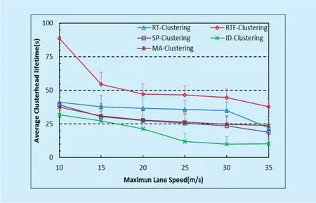
Fig. 2. Average clusterhead lifetime
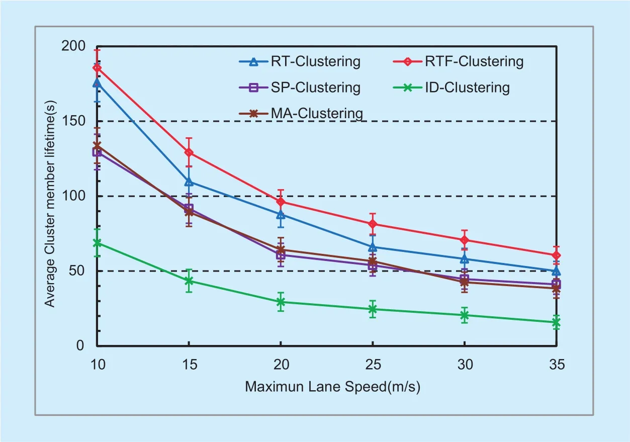
Fig. 3. Average cluster member lifetime.
4) Number of messages sent per node
NMS measures the communication cost for constructing and maintaining clusters. Figure 6 shows the cost of all the algorithms. The message cost includes the on demand messages to construct and maintain clusters. As expected, our algorithm performs better than all others in all cases. This is certainly the bene fit of high stability of clusters constructed. Since our clustering algorithm can construct clusters with high stability, the message cost of cluster construction and maintenance should be much less than SP/MA-Clustering.
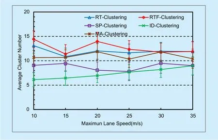
Fig. 4. Average cluster number.
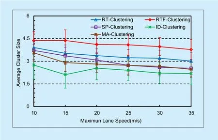
Fig. 5. Average cluster size.
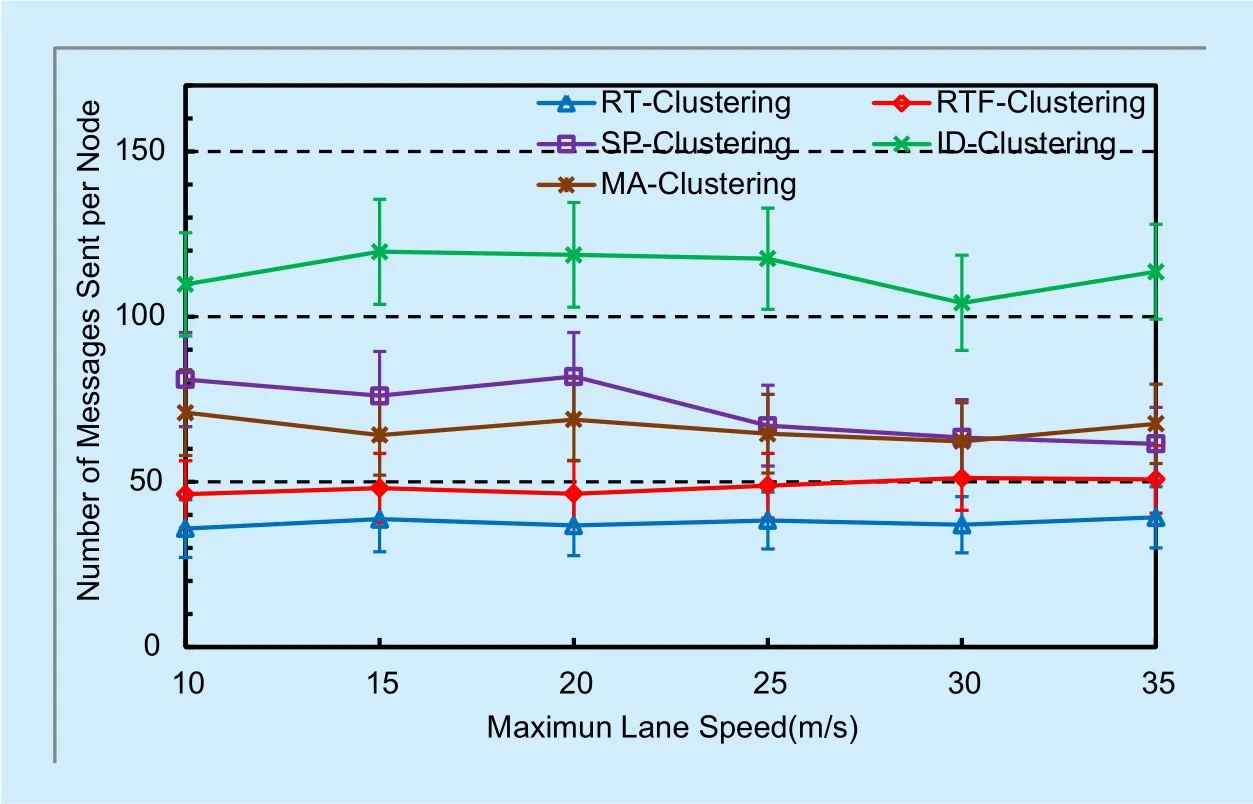
Fig. 6. Number of messages sent per node.
It is more interesting to compare RT-Clustering and RTF-Clustering. RTF-Clustering,the variant with Future-cluster mechanism,causes more communication cost than RT-Clustering, although the difference is not very large. We explain the additional communication cost of RTF as below. Future-clusterhead mechanism needs to exchange messages for merging future-clusters. On the other hand,RT-Clustering may simply keep future-clusters run individually to avoid re-clustering overhead. This is consistent with the results of cluster size in figure 5.
VI. CONCLUSION AND FUTURE WORK
In this paper, we propose a novel clustering algorithm for VANETs by considering navigation route of vehicles. Based on the overlapping road segments of routes from different vehicles, we design a function to estimate the time that two vehicles may keep to be neighbors in future trip. Clusterheads are elected based on the overall time that a vehicle can keep its neighborhood in future. Compared with existing clustering algorithms, our solution can improve cluster stability, in terms of various performance metrics, including lifetime of clusters, number of status changes,which has been con firmed by simulations.
Further study is certainly necessary. Possible directions include constructing models to estimate the probability of being neighbor in future road, optimizing the cluster size with respect to the upper layer applications, and improving the clusterhead election metric using computational intelligence techniques.
ACKNOWLEDGEMENTS
The authors would like to thank the reviewers for their detailed reviews and constructive comments, which have helped improve thequality of this paper. This research is partially supported by The National Key Research and Development Program of China (No.2016YFB0200404), National Natural Science Foundation of China (No. 61501527,61379157, U1711263), MOE-CMCC Joint Research Fund of China (No. MCM20160104),State’s Key Project of Research and Development Plan (No. 2016YFE0122900-3), the Fundamental Research Funds for the Central Universities, the Science, Technology and Innovation Commission of Shenzhen Municipality (JCYJ20160429170032960),Guangdong Science and Technology Project(No.2016B010126003), 2016 Major Project of Collaborative Innovation in Guangzhou(No.201604046008) and Program of Science and Technology of Guangdong (No.2015B010111001).
Reference
[1] P.K Jaiswal, C.D Jaidhar C D, “Location prediction algorithm for a nonlinear vehicular movement in VANET using extended Kalman filter,” Wireless Networks, 2016, pp. 1-16.
[2] H. Gong, L. Yu, N. Liu, X. Zhang, “Mobile Content Distribution with Vehicular Cloud in urban VANETs,” China Communications,vol.13, no. 8,2015, pp. 84-96.
[3] T. Nadeem, S. Dashtinezhad, C. Liao, et al., “The Innovation and Development of Internet of Vehicles,”ACM SIGMOBILE Mobile Computing and Communications Review, vol. 8, no. 3, 2004, pp. 6-19.
[4] W. Zhang, X. Xi, “The Innovation and Development of Internet of Vehicles,” China Communications, vol. 13, no. 6, 2016, pp. 32-47.
[5] C. Yang, J. Tao, H. Zhu, “A Survey of Emerging M2M Systems: Context, Task, and Objective,”IEEE Internet of Things Journal, vol. 3, no. 6,2016, pp. 1246-1258.
[6] S. Vodopivec, J. Bester, A. Kos, “A Survey on Clustering Algorithms for Vehicular Ad-hoc Networks,” Proc. 35th Int’l Conference on Telecommunications, 2012, pp. 52-56.
[7] G. Chen, Y. Wu, “A Wireless Intrusion Alerts Clustering Method for Mobile Internet,” China Communications, vol. 13, no. 4, 2016, pp. 108-118.
[8] H. Su, X. Zhang, “Clustering-Based Multichannel MAC Protocols for QoS Provisionings Over Vehicular Ad Hoc Networks,” IEEE Transactions on Vehicular Technology, vol. 56, no. 6, 2007, pp.3309-3323.
[9] G. Yvonne, W. Bernhard, G.H Peter, “Medium Access Concept for VANETs Based on Clustering,” Proc. Vehicular Technology Conference(VTC), 2007, pp. 2189–2193.
[10] F. Li, Y. Wang, “Routing in Vehicular Ad Hoc Networks: A Survey,” IEEE Vehicular Technology Magazine, vol. 2, no. 2, 2007, pp. 12-22.
[11] L. Bononi, M.D Felice, “A Cross Layered MAC and Clustering Scheme for Efficient Broadcast in VANETs.” Proc. International Conference on Mobile Adhoc and Sensor Systems, 2007, pp. 1-8.
[12] A. Ahizoune, A. Hafid, “A New Stability Based Clustering Algorithm (SBCA) for VANETs,” Proc.IEEE 37th Conference on Local Computer Networks, 2012, pp. 843-847.
[13] H. Hartenstein, K.P Laberteaux, “A Tutorial Survey on Vehicular Ad Hoc Networks,” IEEE Communications Magazine, vol. 46, no. 6, 2008, pp. 164-171.
[14] N. Maslekar, M. Boussedjra, J. Mouzna, et al., “A Stable Cluster-ing Algorithm for Eきciency Applications in VANETs,” Proc. International Conference on Wireless Communications and Mobile Computing Conference, 2011, pp. 1188-1193.
[15] Z.Y Rawshdeh, S.M Mahmud, “Toward Strongley Connected Clustering Structure in Vehicular Ad Hoc Networks,” Proc. International Conference on Vehicular Technology, 2009, pp. 1-5.
[16] R. Jiang, Y. Zhu, X. Wang, et al., “TMC: Exploiting Trajectories for Multicast in Sparse Vehicular Networks,” IEEE Transactions on Parallel and Distributed Systems, vol. 26, no. 1, 2015, 26(1): 262-271.
[17] J. Jeong, S. Guo, Y. Gu, et al., “TBD: Trajectory-Based Data Forwarding for Light-Traffic Vehicular Networks,” Proc. International Conference on Distributed Computing Systems, 2009,pp. 231-238.
[18] E.D Souza, I. Nikolaidis, P. Gburzynski, “A new aggregate local mobility (ALM) clustering algorithm for VANETs,” Proc. International Conference on Communications, 2010, pp. 1-5
[19] K.A Hafeez, L. Zhao, Z. Liao, et al., “A Fuzzy-Logic -Based Cluster Head Selection Algorithm in VANETs,” Proc. International Conference on Communications, 2012, pp. 203-207.
[20] C. Shea, B. Hassanabadi, S. Valaee, et al., “Mobility-Based Clustering in VANETs Using Aきnity Propagation,” Proc. Global Communications Conference, 2009, pp. 1-6.
[21] B. Hassanabadi, C. Shea, L. Zhang, et al., “Clustering in Vehicular Ad Hoc Networks using Aきnity Propagation,” Ad Hoc Networks, vol. 13,no. 1, 2014, pp. 535-548.
[22] S. Ucar, S.C Ergen, O. Ozkasap, et al., “Multihop-Cluster -Based IEEE 802.11p and LTE Hybrid Architecture for VANET Safety Message Dissemination,” IEEE Transactions on Vehicular Technology, vol. 65, no. 4, 2016, pp. 2621-2636.
[23] M. Ni, Z. Zhong, D. Zhao D, et al, “MPBC: A Mobility Prediction-Based Clustering Scheme for Ad Hoc Networks,” IEEE Transactions on Vehicular Technology, vol. 60, no. 9, 2011, pp. 4549-4559.
[24] M.M Morales, C.S Hong, Y, Bang, et al., “An Adaptable Mobility-Aware Clustering Algorithm in vehicular networks,” Proc. Asia-pacific Network Operations and Management Symposium,2011, pp. 1-6.
[25] M.M.M Nasr, A.M Abdelgader, Z. Wang, et al.,“VANET Clustering Based Routing Protocol Suitable for Deserts,” Sensors, vol. 16, no. 4, 2016,pp. 1-23.
[26] C. Caballerogil, P. Caballerogil, J. Molinagil, et al.,“Self-Organized Clustering Architecture for Vehicular Ad Hoc Networks,” International Journal of Distributed Sensor Networks, vol. 5, 2015, pp. 1-12.
[27] H. Wang, R.P Liu, W. Ni, et al., “VANET Modeling and Clustering Design Under Practical Traffic,Channel and Mobility Conditions,” IEEE Transactions on Communications, vol. 63, no. 3, 2015,pp. 870-881.
[28] W. Li, A. Tizghadam, A. Leon-Garcia, “Robust Clustering for Connected Vehicles Using Local Network Criticality,” Proc. International Conference on Communications, 2012, pp. 7157-7161.
[29] S.A Mohammad, C.W Michele, “Using Traffic Flow for Cluster Formation in Vehicular Adhoc Networks,” Proc. Local Computer Networks,2010, pp. 631-636.
[30] F.D Cunha, L.A Villas, A. Boukerche, et al., “Data Communication in VANETs: Protocols, Applications and Challenges,” Ad Hoc Networks, vol. 44,2016, pp. 90-103.
[31] L. Li, Z. Yang, J. Wang, et al., “Network Coding with Crowdsourcing-based Trajectory Estimation for Vehicular Networks,” Journal of Network and Computer Applications, vol. 64, no. C, 2016,pp. 204-215.
[32] F. Xu, S. Guo, J. Jeong, et al., “Utilizing Shared Vehicle Trajectories for Data Forwarding in Vehicular Networks,” Proc. International Conference on Computer Communications, 2011, pp. 441-445.
[33] C. Lin, M. Gerla, “Adaptive Clustering for Mobile Wireless Networks,” IEEE Journal on Selected Areas in Communications, vol. 15, no. 7, 1997, pp.265-1275.
杂志排行
China Communications的其它文章
- Service Function Chain in Small Satellite-Based Software De fined Satellite Networks
- Impact of Phase Noise on TDMS Based Calibration for Spaceborne Multi-Beam Antennas
- A Novel Roll Compensation Method for Two-Axis Transportable Satellite Antennas
- Coordinated Resource Allocation for Satellite-Terrestrial Coexistence Based on Radio Maps
- Heuristic Solutions of Virtual Network Embedding: A Survey
- Stochastic Dynamic Modeling of Rain Attenuation: A Survey
