A Novel Roll Compensation Method for Two-Axis Transportable Satellite Antennas
2018-04-04LaidingZhaoJidongXieXiaodongBaiZhichengQu
Laiding Zhao , Jidong Xie , Xiaodong Bai , Zhicheng Qu
1 College of Telecommunications and Information Engineering, Nanjing University of Posts and Telecommunications, Nanjing 210003, China
2 Satellite Communication and Navigation Collaborative Innovation Center, Nanjing 210003, China
I. INTRODUCTION
Currently, transportable satellite antennas(TSAs) can be categorized into four-axis [1],three-axis [2]-[5] and two-axis (TA) [3]-[9]kinds based on the structure of antenna pedestal. Since four-axis and three-axis antenna platforms have higher tracking costs, then the TA platform is widely adopted in transportable satellite communication systems due to its advantages of simpler mechanical structure and much lower cost. Generally, there are several methods to measure the pitch and roll angle of TATSAs. The inertial navigation system(INS) with high-precise gyroscope can read high space directing accuracy but this method is expensive [10]. Using differential global positioning system (GPS) to determine the azimuth direction also has disadvantages of slow locating output rate and long installation baseline even though it has a medium cost[11], [12]. When utilizing the electronic compass, due to the disturbance of the magnetic declination and environmental magnetic field,horizontal rotating calibration for long period of time is needed to avoid severe directing deviation [13]. Therefore, all these methods have limitations in engineering realization.
The principle of gravity acceleration can also be adopted to measure the pitch and roll angle with a much lower cost than the aforementioned methods [14]-[16]. When horizontally placed it has the highest accuracy and the measure error increases with the increased tilt angle. Based on this, the acceleration sensor should be directed at a certain angle from the axis of antenna beam in practical engineering design. However, when the roll axis is non-ze-ro, there will be a shift to both the azimuth angle and the pitch angle of the TSAs, which will deteriorate the received signal. Satellite antennas with roll axis can easily sense the angle variation and compensate it by means of turning the roll axis around. However, for the low cost TA, it only has the azimuth and elevation axes due to its simple structure.Thus, conventional TATSAs receivers in sale track the target satellite by using wide-range tracking. However, this method has a very long tracking time and it will even fail to work in some conditions such as large roll angle.Thus, users are usually asked to lay antennas horizontally to the greatest extent to ensure reliable link performance.
In order to solve these problems of TATSAs,we propose a novel roll compensation (RC)method for the low-cost TATSAs to achieve faster tracking even if when the antenna has no azimuth sensor. By analyzing projection of the change of roll axis to the azimuth elevation and polarization axes, formulas of the tracking method are derived. Also, simulations of measuring error are conducted. Results indicate that with roll angle ≤ 30°, utilizing the RC method enables system to lock satellite by only a single round of tracking, which increases the efficiency of initial searching step remarkably. In addition, compared with conventional tracking modes, tracking in the ellipse trace with the RC method provides the highest tracking efficiency. Experiments show that the RC method is an effective engineering method.
The paper proposes a novel roll compensation (RC) method for the low-cost TATSAs to achieve faster tracking even if when the antenna has no azimuth sensor.
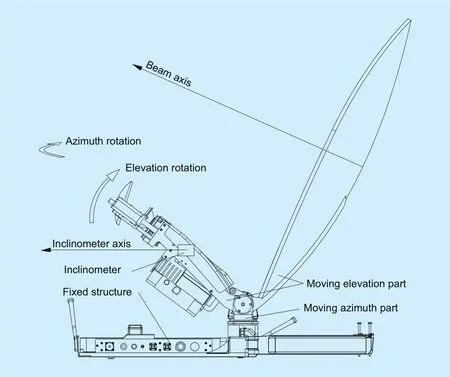
Fig. 1. Structure of the TATSA system.
II. MECHANICAL STRUCTURES OF TATSA
Generally, the structures of the TATSA pedestal structure can be classi fied into X-Y pedestals [17]-[19] and elevation-over-azimuth pedestals [20], [21]. For X-Y pedestals, when the target satellite has a lower pitch angle, the outputs of the control system will have large variation, which requires a much stricter overloading than elevation-over-azimuth pedestals.Meanwhile, this variation requires higher tracking speed and acceleration, which makes the system dif ficult to react in time. Therefore,X-Y pedestals tend to lose the target satellite in the scenario of low orbit pitch angle.
For elevation-over-azimuth pedestals, the azimuth is the angle between antenna pointing and due north, where the positive angular values are assumed to be corresponding to clockwise. The elevation is the angle between terminal-satellite link and the horizon, where the positive angular values are assumed to be corresponding to upper angles. When the target satellite is geostationary earth orbit (GEO)satellite, the TATSA system can track the target accurately and stably. When the target satellite is polar-orbit satellite with lower pitch angle, the azimuth axis can also achieve stable tracking. When the target satellite passes over the top, the azimuth axis should turn around 180° instantly. This requires infinite angular speed and acceleration, which is very hard to realize. However, in practical application of TATSA systems, the scenario of target satellite passing over the top seldom appears in the antenna’s elevating mode. Therefore, proposed RC method will be discussed and analyzed based on the common elevation-over-azimuth pedestals TATSA system.
The speci fic structure diagram of the TATSA system is shown in figure 1. The locations and rotation modes are also shown in the figure. Three electric motors, i.e., the azimuth motor, the elevation motor and the polarization motor, are used in the TATSA structure.
III. THEORETICAL MODEL
In this section, three-axis earth coordinate system and three-axis geographic coordinate system are used for discussion, respectively.As shown in figure 2, earth coordinate system is set as OeXeYeZe, which take the geocentre as origin and OeZe-axis as the direction of due north of earth. Plane OeXeYeis in the equatorial plane with OeXe-axis pointing longitude 0° and OeYe-axis pointing east longitude 90°. The geographic coordinate system is set as OXgYgZgwhich take the pattern of the north-east-ground coordinate system with OXg-axis pointing to north, OYg-axis pointing to east and OZg-axis pointing to the gravity direction, respectively.
Assumingrsat_cenandrstation_cenare vectors from geocentre to the target satellite and the TATSA system, respectively, in earth coordinate system. After transform from earth coordinate system to geographic coordinate system, we can get

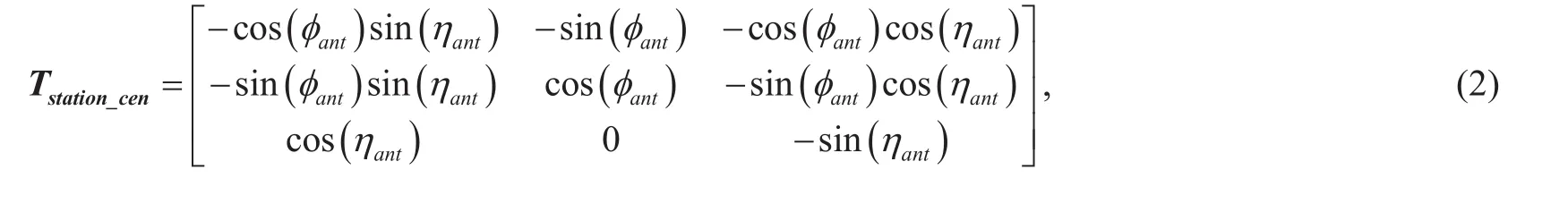
WhereTstation_cenis the transition matrix, which can be written as [12]-[16] shown in bottom at this page.
Here φsatand ηsatare the longitude and latitude of the TATSA system, respectively.
Assuming the polarization angle of satellite is κsat, φsatand ηsatare the longitude and latitude of the satellite, therefore, the transition from the satellite coordinate system to the earth coordinate system can be seen as the rotation around OeXe-axis by κsatfirst, then OeYe-axis by −ηsat, and finally OeZe-axis by φsatin order, respectively. These can be respectively represented by:
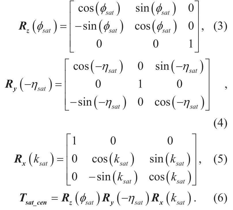
The transition matrix from the satellite to receiving station can be calculated as:

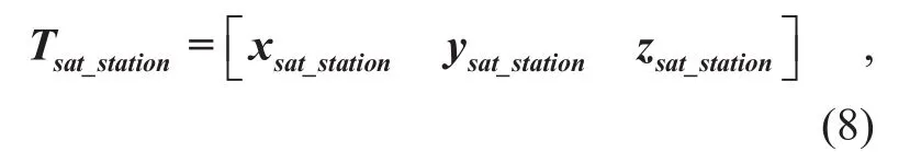
whereTsat_stationcan be also written as:
Thus, the theoretical locating matrix of the receiving station can be described as:
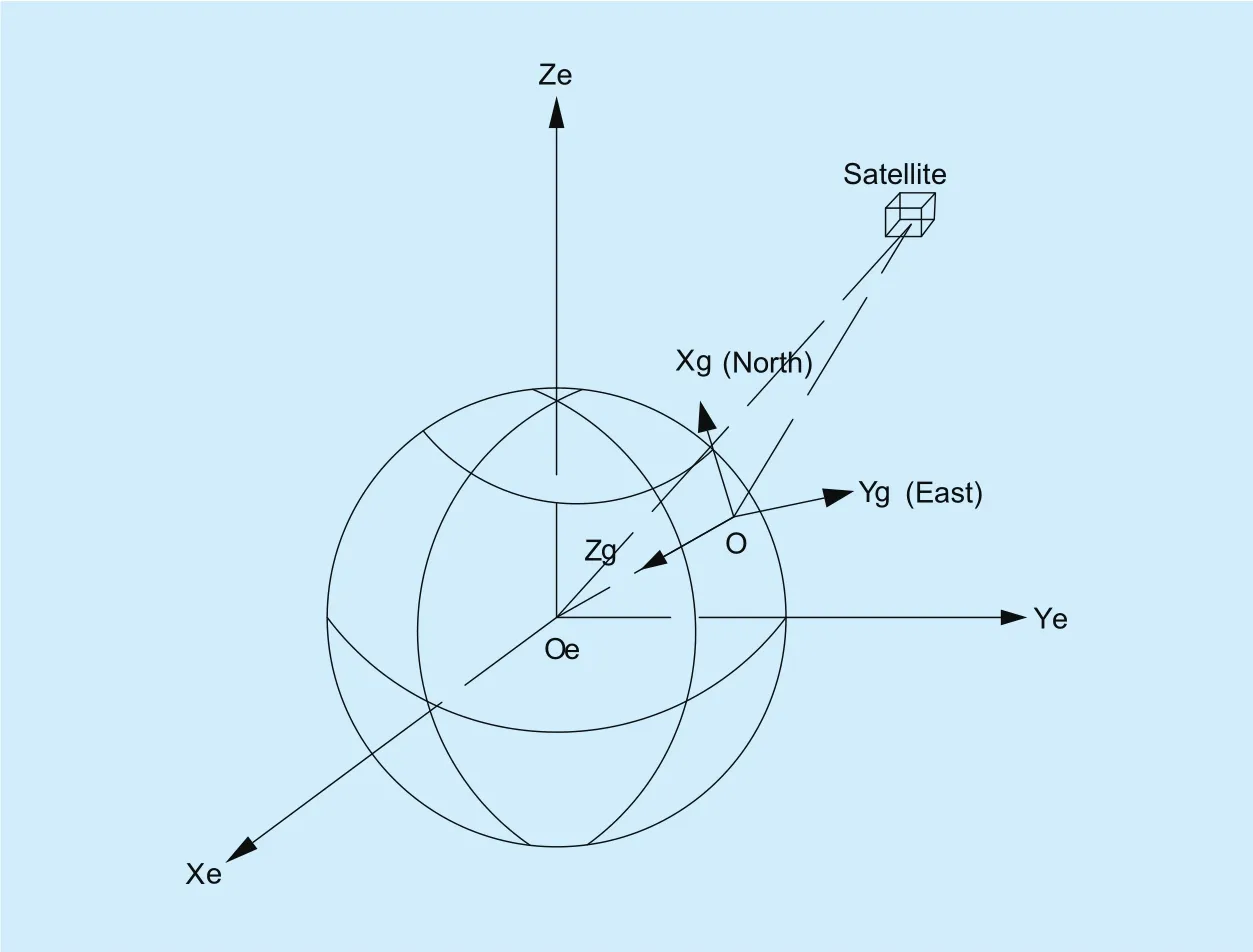
Fig. 2. Satellite in the geographic coordinate system.
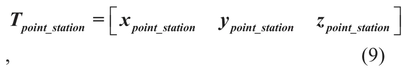
where each coordinate component is given as:
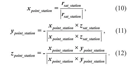
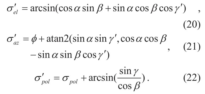
Assuming that σel, σazand σpolare the theoretical locating elevation, azimuth and polarization angles of the receiving station. As a result, they can be finally derived as follows,respectively:
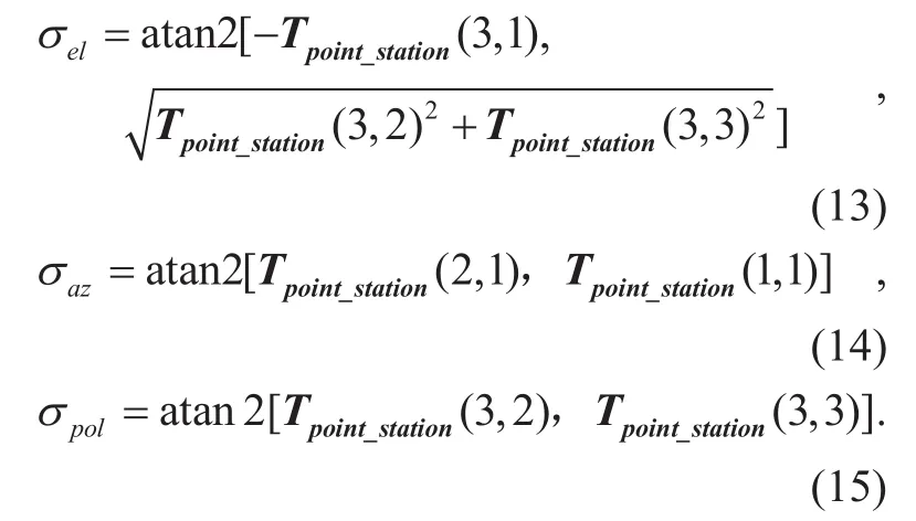
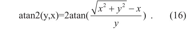
To be noticed, the atan2 (*, *) in formulas is a function, and it is de fined as:
IV. PROPOSED RC METHOD
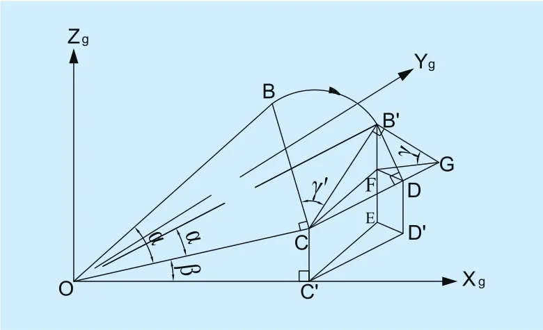
Fig. 3. Schematic diagram of the beam change caused by the roll angle variation.
The existence of the roll angle will diverge the antenna’s direction from the satellite, which tends to cause loss of satellite. Also, it is hard to search for the satellite since the searching trace will be tilted when the roll angle exists. However, since the TATSA system does not have roll axis, the angle generated in the roll direction cannot be compensated for by roll axis. Therefore, to maintain azimuth and elevation angles (in geographic coordinate system) of the antenna in the TATSA system,three-axis compensation must be conducted to project the change of roll axis to azimuth elevation and polarization axes by means of adjusting corresponding motors. Such compensation is the key to locking the satellite accurately.
Generally, three-dimensional derivation is adopted to achieve compensation [22]-[27]owing to the high accuracy of three-dimensional space sensor. However, these sensors are dif ficult to apply due to high costs. Therefore, wide scanning is the common searching method in engineering applications. In this section, the proposed RC method, which can ensure the accuracy in the elevation and polarization without azimuth sensor, is presented.Meanwhile, it enables antennas to search for the satellite quickly under the circumstance of one-dimension vague.
As discussed before, cheap tilt sensors commonly base on gravity acceleration principle. The performance of these sensors will be worse when the pitch angle becomes wider.Based on this reason, there should be a fixed angle α(∠BOC) between elevation axis and the beam axis in sensor coordinate system. In figure 3, OB represents the beam axis. Assuming the elevation angle of the tilt sensor to be β(∠C′ OC) and the roll angle γ(∠FGB′) to be 0°, the elevation axis of the sensors and the roll axis are parallel to OC and CD, respectively. Thus, the tilt sensor can be shifted to be placed in C on plane OCD. When all the outputs of three dimensions are zero, sensor coordinate system coincides with geographic coordinate system.
When the roll angle exists, CB rotates to CB′ by γ′(∠B′ GD). Let B′ D be parallel to BC and plane CFD is actually the projection of plane CB′ D on the horizontal plane. Also,plane OC′ D′ is the projection of plane OCD on the horizontal plane through point O. Ifthen we can get

Here we establish the antenna coordinate system as OXaYaZa. Assuming that the geographic azimuth of the tilt sensor is ϕ, if ϕ= α=β =γ=0, then OXaYaZacoincides with
Since OXaYaZacan be actually generated by rotating OXgYgZgfor several times, the rotation matrix is given as:

From the rotating relationship in the last section, (17) can be given as (19) shown in the bottom at this page.
Assuming the antenna’s elevation azimuth and polarization angle are σe′l, σa′zand σ′pol,respectively, the angles can be given as:
Finally, according to the result from Eq.(20) to (22), we can conduct roll compensation in the TATSA system.
The theoretical alignment angle σel, σazand σpolof two-axis transportable satellite antenna (TATSA) on satellite communication earth station, according to the latitude and longitude of current earth station and satellite parameters, can be derived using proposed formulas (1)~(16). The beam angle σe′l, σa′zand σ′polof satellite antenna, according to the two-dimensional angle output by the tilt sensor on satellite communication earth station and position of the tilt sensor relative to the antenna surface, can be derived using proposed formulas (17)~(22). Above calculation can be realized by DSP. The DSP can drive the motors to reduce the difference between σe′l,σa′z, σ′poland σel, σaz, σpol. This is the socalled correction process.
V. SIMULATION RESULTS AND DISCUSSIONS
5.1 Pointing angle deviation
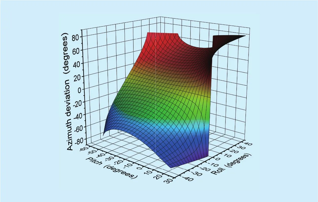
Fig. 4. Azimuth deviation.
Fig. 5. Pitch deviation.
When antennas have roll angle, the real three-dimensional attitude angle will be deviated from the original one without the roll angle. These deviations can be denoted by δel,δazand δpol, respectively, which are further represented as

Figure 4~figure 6 show simulated results of the azimuth elevation and polarization deviation of the TATSA system. Here antenna’s beam angle is assumed to be 2°, α=63.48°,0°≤α+β<90°, −45°≤γ≤45°.
From Fig. 4 we can see that when the roll angle γ=0°, the azimuth deviation is zero.When γ is nonzero, the azimuth deviation is highly related to the pitch angle β and the roll angle γ. For instance, the azimuth deviation increases with the increased roll angle. When the roll angle is less than 10°, the azimuth deviation is nearly linear to the roll angle.
From Fig. 5, under the circumstance of the fixed pitch angle, larger absolute value of roll angle will lead to higher pitch deviation.Results indicate that when 0°≤α+β<80°,and − 7°≤γ≤7°, the pitch deviation is less than 1.914°, which is also less than the beam angle. Thus, adopting dynamic approaching scanning method will find the largest angle. When −15°≤γ≤15°, the pitch deviation reaches 7.202°, which will impose a severe influence on the locating satellite.When −30°≤γ≤30°, the pitch deviation is 20.072°
From figure 6, larger roll angle will lead to higher polarization deviation. When the roll angle is relatively small, the polarization deviation is proportional to the roll angle approximately. The deviation of the space direction sensor is resulted from several reasons such as the direction error caused by the antennas’roll angle and the disturbance on antennas. In following part, the performance evaluation of the proposed error compensation method will be separated into two parts: the error compensation in initial searching step and the error compensation after losing the satellite.
5.2 Error compensation in initial searching step
The general method of initial searching for the target satellite has three steps: (a) add a fixed deviation angle on the output of the pitch angle sensor; (b) raise the pitch and polarization angle to the theoretical value; and (c)change the fixed pitch angle and then repeat the azimuth one-dimensional searching if the searching fails in the last round of operation,respectively.
As discussed before, assuming the beam angle of antennas to be 2° and the roll angle γ>7°, if no deviating compensation has been taken, the azimuth searching trace will be a slant with a certain angle to horizontal plane,which makes the deviation larger than 1.9°.As a result, the azimuth searching cannot lock satellite in only one time and the initial searching time will be very long. However, after adopting the proposed RC method, if the tilt sensor is accurate, then the TATSA system can ensure locking the target satellite within only one azimuth searching.
Since the tilt sensor with high accuracy is usually expensive, then the accuracy level must be considered in practical engineering application.
Assuming that the two axes’ outputs of an tilt sensor, whose accuracies are 1°, are β0and γ0, α=63.48°, α+β=52.5°,−30°≤γ≤30°.Thus,

Thus the pitch deviation ∆′el, brought by accuracy after inclined angle compensation can be given as (28) shown in the bottom at this page.
Assuming γ0to be 0°, 10°, 20° and 30°, respectively, the simulated results of ∆′elare shown in figure 7.
From figure 7 we can see that wider roll angle will lead to lower inclined angle accuracy level as well as higher ∆′el. If the required precision of initial searching pitch angle is 1°,with the roll angle of −30°≤γ≤30°, in order to ensure the accuracy of initial searching, the accuracy of tilt sensor must be superior to 1°.Thus, in this paper, the accuracy is chosen as 0.5°.
5.3 Error compensation after losing the satellite
Fig. 7. Pitch deviation brought by accuracy after inclined angle compensation.

After the antenna locking the satellite, some disturbance will cause losing the target. At the beginning of losing target, satellite must be near the beam direction of the antenna. Commonly, two kinds of searching methods can be adopted: (a) operating the azimuth and el-evation motor in different time with the space trace to be a rectangular; and (b) operating the azimuth and elevation motor at the same time with the space trace to be an ellipse. In the presence of the roll angle, both the rectangular and ellipse trace will be inclined. By adopting the RC method, the long side of rectangular trace and the major axis of ellipse trace will be parallel to X-axis, respectively.
Assuming that the accuracy of antenna tilt sensor is 0.5°. The theoretical two-dimension direction coordinates are set at (168.4°,52.1°) and the actual coordinates after losing satellite are set at (159.2°, 49.6°), which has a (−9.2°, −2.5°) deviation. The roll angle of antenna is assumed to be 10° Both the azimuth and elevation searching speed are 0.04° /ms. When the antenna’s beam enters the circle with the center at (168.4°, 52.1°)and the radius equal to 2°, the target satellite is deemed to be locked. We simulate four different searching traces including inclined rectangular, rectangular, inclined ellipse and ellipse trace searching. Results are provided in figure 8 with t to be the searching time.
From figure 8, both searching along the rectangular and ellipse trace need less searching time than their inclined version.
To avoid contingency, simulations have been done under different deviating conditions. The value of original deviation and the comparison of the searching time are shown in Table I, respectively.
Fig. 8. The simulated searching trace with the original deviation of (−9.2°,−2.5°).
We can see from Table.1 that when the azimuth is less than 4°, the difference of the searching time is small. When azimuth is more than 4° and less than 10°, searching in the rectangular trace can save searching time. However, when the azimuth is more than 10°, the searching time will be much longer.Besides, comparing with other three methods,the ellipse trace searching method needs much less searching time in most conditions. Especially, under the circumstance of large deviations, adopting the ellipse trace will reduce the searching time remarkably. Therefore, with the proposed RC method, searching in the ellipse trace can improve the tracking efficiency effectively.
VI. ENGINEERING TEST
In order to verify the effectiveness of the proposed method, we experimentally searched ChinaSat 6A, which has the theoretical coordinates of (168.4°, 52.1°), with a TATSA.The accuracy of the antenna tilt sensor is 0.5°. Both the azimuth and elevation searching speed are 0.04°/ms. The received signals of the TATSA are ampli fied by LNA and then demonstrated in spectrum analyzer as well as satellite beacon receiver (SBR), respectively.SBR output voltage is collected by the controller. The test environment is shown in figure 9.
First step is to test initial searching of antenna. Assuming the actual coordinates are set at (159.2°, 49.6°). figure 10 and 11 show the output signals of SBR without and with the proposed RC method, respectively.
Moreover, by substantive testing with variable initial direction of TATSA and no roll compensation, results show that with the roll angle less than 5° and the pitch angle at its theoretical value, the system can track the satellite only by azimuth rotation. However, the pitch angle should be adjusted for much more times to track the satellite hardly with a larger roll angle. After the proposed method is adopted, the azimuth need to be rotated only one time with the roll angle of −30°≤γ≤30°.This veri fies the correctness of the RC method,which also increases the tracking efficiency.
Finally, the condition for satellite searching of the TATSA with the disturbance is tested.Assuming the initial direction of the TATSA to be (180.4°, 56.1°), figure 12 shows theoutput voltages of SBR by adopting the inclined rectangular, rectangular, inclined ellipse and ellipse trace searching, respectively. The results are consistent with those in Table 1,which proves the correctness of the simulated analysis. Moreover, it can be concluded that the ellipse trace searching method with the proposed RC method has the highest efficiency.
Table I. Comparison among four different searching methods
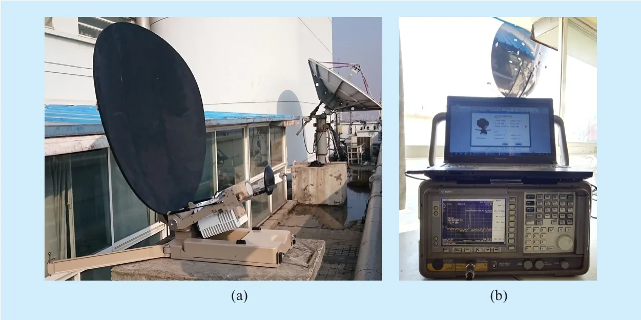
Fig. 9. Test environment.
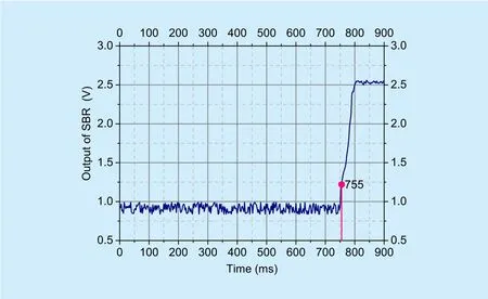
Fig. 10. Output of SBR without RC.
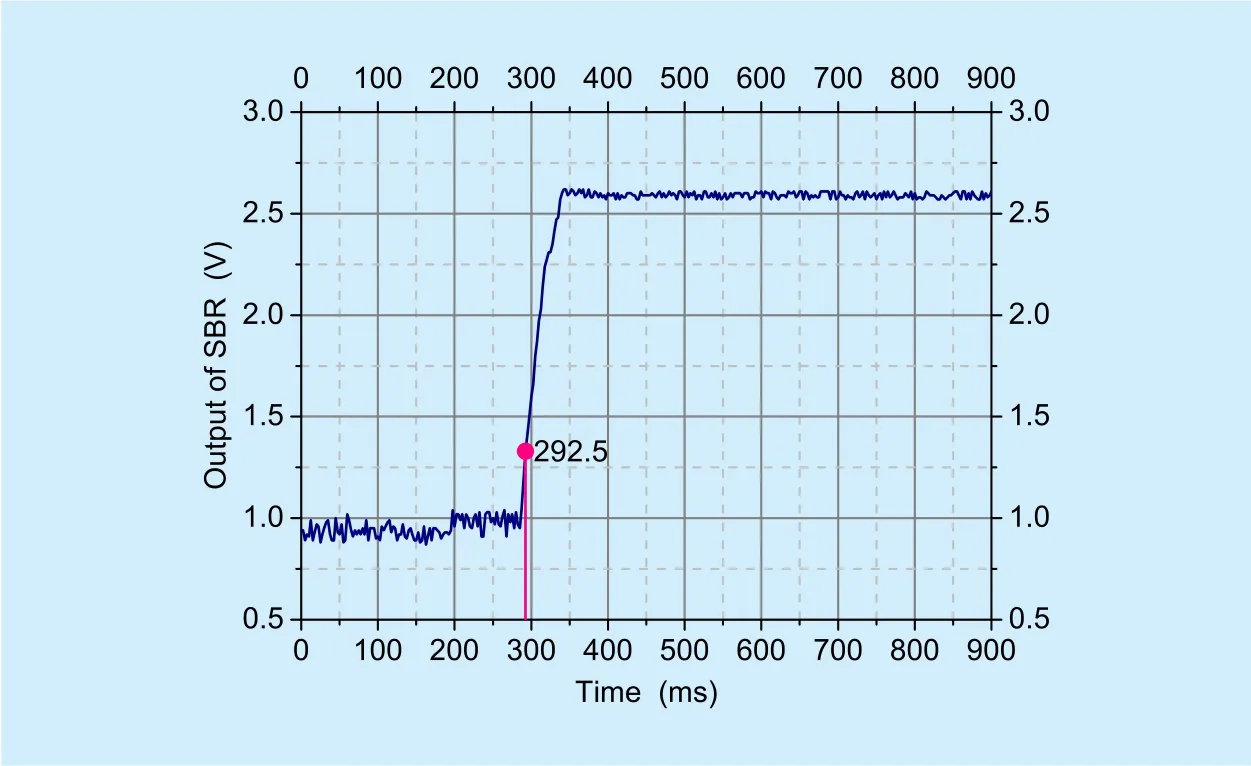
Fig. 11. Output of SBR with RC.
VII. SUMMARY
The TSA system based on the simplified TA structure features it slow costs on machinery and sensors. However, the in fluence of antenna roll angle is non-ignorable. In order to avoid wide-range searching, shorten the searching time and even lock satellites in extreme scenarios, we propose a novel three-axis RC method. The method can effectively ensure the accuracy of the pitching and polarization even though in the absence of azimuth sensor. Simulation and measurement results have proved that the proposed RC method can effectively reduce the initial searching time for the sat-ellite. By searching in the ellipse trace, the TATSA system will have the highest searching efficiency in most conditions.
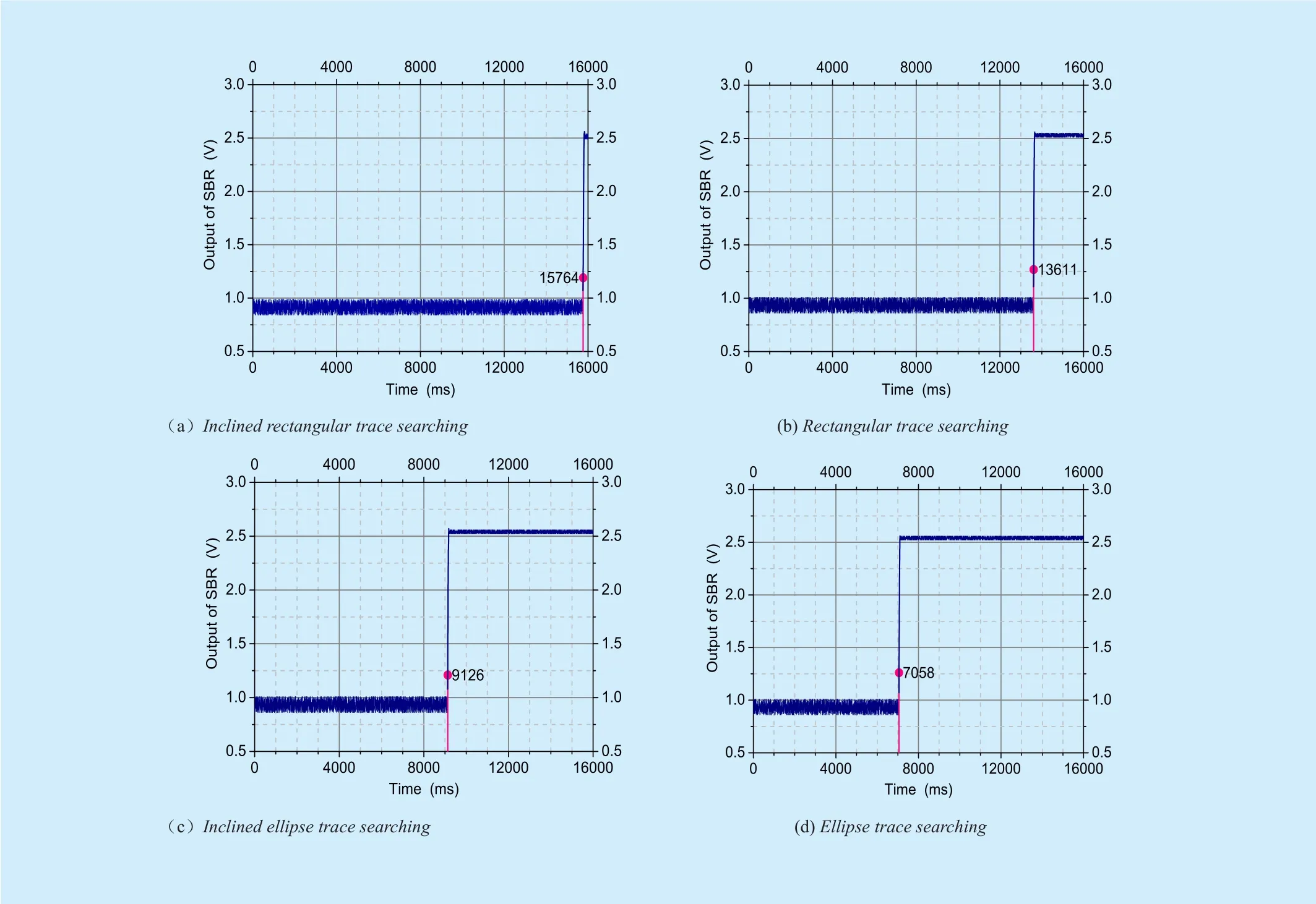
Fig. 12. Output of SBR after losing the satellite with the original deviation of (12°,4°).
ACKNOWLEDGEMENTS
This work was jointly sponsored by scientif
ic research foundation NUPTSF (Grant No.NY-214144 and Grant No. NY-215073), and NSFC (Grant No. 61701260).
[1] M. D. Baldé, S. Avrillon, C. Brousseau, D. Lemur,and B. Uguen, “Spatial scanner channel sounder for space diversity studies,” Proc. 2016 10th European Conference on Antennas and Propagation (EuCAP), 2016, pp. 1-3.
[2] T. Matsuzaki, M. Takemoto, S. Ogasawara, S.Ota, K. Oi, and D. Matsuhashi, “Novel Structure of Three-Axis Active-Control-Type Magnetic Bearing for Reducing Rotor Iron Loss,” Ieee Transactions on Magnetics, vol. 52, Jul. 2016, pp.1-4.
[3] S. Leghmizi, S. Liu, R. Fraga, and A. Boughelala,“Dynamics Modeling for Satellite Antenna Dish Stabilized Platform,” Machine Design and Manufacturing Engineering, vol. 566, 2012, pp. 187-196.
[4] P. C. P. Chao and C.-W. Chiu, “Design and experimental validation of a sliding-mode stabilizer for a ship-carried satellite antenna,” Microsystem Technologies-Micro-and Nanosystems-Information Storage and Processing Systems, vol.18, Sep. 2012, pp. 1651-1660.
[5] B. Bishop, R. Gargano, A. Sears, and M. Karpenko, “Rapid maneuvering of multi-body dynamic systems with optimal motion compensation,”Acta Astronautica, vol. 117, Dec. 2015, pp. 209-221.
[6] X. Zhou, H. Zhang, and R. Yu, “Decoupling control for two-axis inertially stabilized platform based on an inverse system and internal model control,” Mechatronics, vol. 24, Dec 2014, pp.1203-1213.
[7] M.-J. Jeon and D.-S. Kwon, “An optimal antenna motion generation using shortest path planning,” Advances in Space Research, vol. 59, Mar.15 2017, pp. 1435-1449.
[8] Z. F. Bai, Y. Q. Liu, and Y. Sun, “Investigation on dynamic responses of dual-axis positioning mechanism for satellite antenna considering joint clearance,” Journal of Mechanical Science and Technology, vol. 29, Feb. 2015, pp. 453-460.
[9] J. Wan, S. Lu, X. Wang, and Y. Ai, “A Steerable Spot Beam Re flector Antenna for Geostationary Satellites,” IEEE Antennas and Wireless Propagation Letters, vol. 15, 2016, pp. 89-92.
[10] Y. Chen, S. Zhao, and J. A. Farrell, “Computationally Eきcient Carrier Integer Ambiguity Resolution in Multiepoch GPS/INS: A Common-Position-Shift Approach,” IEEE Transactions on Control Systems Technology, vol. 24, Sep. 2016,pp. 1541-1556.
[11] B. Hou, X. Zhang, “A Dual-Satellite GNSS Positioning Algorithm of High Accuracy in Incomplete Condition,” China Communications, vol.13,no. 10, Oct. 2016, pp.58-68.
[12] Z. Wu, M. Yao, H. Ma, W. Jia, and F. Tian, “Low-Cost Antenna Attitude Estimation by Fusing Inertial Sensing and Two-Antenna GPS for Vehicle-Mounted Satcom-on-the-Move,” IEEE Transactions on Vehicular Technology, vol. 62,Mar. 2013, pp. 1084-1096.
[13] P. C. Farese, G. Dall’Oglio, J. O. Gundersen, B. G.Keating, S. Klawikowski, L. Knox, et al., “COMPASS: An upper limit on cosmic microwave background polarization at an angular scale of 20 ‘,” Astrophysical Journal, vol. 610, Aug. 2004,pp. 625-634.
[14] C. Chen, H. Qiushi, J. Shiyu, Z. Wei, and Z. Fuxue, “Research and design of micro-machined gas-pendulum dual-axis tilt sensors commonmode restraining acceleration interference,”Proc. 2008 International Conference on Information and Automation, 2008, pp. 1485-1489.
[15] P. Gui, L. Tang, and S. Mukhopadhyay, “MEMS based IMU for tilting measurement: Comparison of complementary and kalman filter based data fusion,” Proc. 2015 IEEE 10th Conference on Industrial Electronics and Applications (ICIEA),2015, pp. 2004-2009.
[16] T. H. Tsai, W. C. Chou, W. Y. Lin, and M. Y. Lee,“The design of a tilt sensing companion chip for accelerometers,” Proc.2016 IEEE International Conference on Consumer Electronics-Taiwan(ICCE-TW), 2016, pp. 1-2.
[17] M. Tavan, A. Khaki-Sedigh, M. R. Arvan, and A.R. Vali, “X-Y pedestal: partial quasi-linearization and cascade-based global output feedback tracking control,” Nonlinear Dynamics, vol. 81,Aug. 2015, pp. 1459-1473.
[18] A. Taheri, M. A. Shoorehdeli, H. Bahrami, and M.H. Fatehi, “Implementation and Control of X-Y Pedestal Using Dual-Drive Technique and Feedback Error Learning for LEO Satellite Tracking,”IEEE Transactions on Control Systems Technology, vol. 22, Jul. 2014, pp. 1646-1657.
[19] N. M. Tehrani, E. Javanfar, A. Vali, H. M. Tehrani,and IEEE, “Full Extracting Kinematic and Dynamic Equations of X/Y Pedestal with Velocity Analysis,” 2014 Cacs International Automatic Control Conference (Cacs 2014), 2014, pp. 215-221.
[20] B. K. Chung, H. T. Chuah, and J. W. Bredow, “A microwave anechoic chamber for radar-cross section measurement,” IEEE Antennas and Propagation Magazine, vol. 39, Jun. 1997, pp. 21-26.
[21] G. Cortes-Medellin and T. Herter, “Optical de-sign of CCAT - art. no. 62672F,” Proc. Conference on Ground-Based and Airborne Telescopes, Orlando, FL, 2006, pp. F2672-F2672.
[22] Q. Fan and Y. Wang, “Design of Vehicle Antenna Servo Tracking System Controller,” Proceedings of the International Conference on Advances in Mechanical Engineering and Industrial Informatics, vol. 15, 2015, pp. 887-892.
[23] M. N. Soltani, R. Izadi-Zamanabadi, and R.Wisniewski, “Reliable Control of Ship-Mounted Satellite Tracking Antenna,” IEEE Transactions on Control Systems Technology, vol. 19, Jan. 2011,pp. 221-228.
[24] T. Shiozumi, A. Ming, T. Kida, C. Kanamon, Y. Kobayashi, M. Satoh, et al., “Vibration suppression of ship-mounted antennas using a nonlinear passive vibration isolator,” Proc. 2007 IEEE International Conference on Integration Technology,Proceedings, 2007, pp. 568.
[25] H. C. Tseng and D. W. Teo, “Ship-mounted satellite tracking antenna with fuzzy logic control,”IEEE Transactions on Aerospace and Electronic Systems, vol. 34, Apr. 1998, pp. 639-645.
[26] A. Ming, T. Yamaoka, T. Kida, C. Kanamori,and M. Satoh, “Accuracy improvement of ship mounted tracking antenna for satellite communications,” Proc. 2005 IEEE International Conference on Mechatronics and Automations, Vols 1-4, Conference Proceedings, 2005, pp. 1369-1374.
[27] S. Leghmizi and L. Sheng, “Kinematics Modeling for Satellite Antenna Dish Stabilized Platform,”Proc. 2010 International Conference on Measuring Technology and Mechatronics Automation,2010, pp. 558-563.
杂志排行
China Communications的其它文章
- Stochastic Dynamic Modeling of Rain Attenuation: A Survey
- Heuristic Solutions of Virtual Network Embedding: A Survey
- A Survey on Smart Collaborative Identi fier Networks
- Service Function Chain in Small Satellite-Based Software De fined Satellite Networks
- Coordinated Resource Allocation for Satellite-Terrestrial Coexistence Based on Radio Maps
- Impact of Phase Noise on TDMS Based Calibration for Spaceborne Multi-Beam Antennas