Identification of crystal orientation for turbine blades with anisotropy materials
2018-03-21YunqiuTANChopingZANGBioZHOUXioweiWANGPETROV
Yunqiu TAN,Choping ZANG,*,Bio ZHOU,Xiowei WANG,E.P.PETROV
aJiangsu Province Key Laboratory of Aerospace Power System,Nanjing University of Aeronautics and Astronautics,Nanjing 210016,China
bSchool of Engineering of Informatics,University of Sussex,Brighton BN19QT,United Kingdom
1.Introduction
Turbine blades are operated on complex thermal and mechanical loads with thermal resistance,thermomechanical fatigue,creep and stress rupture problems.1–3In order to improve the performance capabilities of turbine blades in the operating environments such as high temperature and the conditions of high and low cycle fatigues,nickel-based superalloys are widely used as materials for gas turbine blades.Generally,nickel-based crystal superalloys include Single Crystal(SC)and Directionally Solidified(DS)alloys,and furthermore their materials are Face-Centred Cubic(FCC).4The single crystal blade consists of one columnar grain and can be modelled as orthotropic material in the lattice directions,while the directionally solidified blade consists of several columnar grains and can be modelled as transverse isotropic by assuming that the number of the columnar grains included in the blade is large.5Nickel-based turbine blades are directionally solidified during the casting process with the crystallographic direction[0,0,1]aligned with the blade stacking axisZ.Practically,this alignment of blade stacking axis,Z,with crystal primary axis,[0,0,1],is variable and controlled within 15°,known as the primary angle,marked as θ.6
Actually,the characteristics of dynamics,fatigue failure and elastic stresses are variable for the turbine blades with different crystal orientations.So,it is paramount to achieve the crystal orientations of arbitrary turbine blades before processing numerical calculations for them.Until now,two methods,which are Electro-Back Scattered Diffraction(EBSD)and Rotating Orientation X-Ray Diffraction(RO-XRD),have been developed to measure the crystal orientation of turbine blades with anisotropy materials.7–9Both methods can provide approximate results in measuring the crystal orientation angles.However,increasing the withdrawal velocity will result in a higher misorientation during directional solidification and a higher initial deviation will cause a more severe increase in misorientation after withdrawal transition.Besides,complex and expensive equipment is essential in the measuring process for previously developed methods.
In this paper,a method based on enhanced mode basis is developed to linearly express the mode shapes of arbitrary turbine blades.The proposed enhanced mode basis can be effectively used for modal analysis of blades with arbitrary crystal orientations.Surrogate model based on Kriging method is also introduced for solving the eigenproblem of blades under arbitrarily distributed crystal orientation with high efficiency and accuracy during the process.Finally,genetic algorithm is employed to identify the crystal orientations of turbine blades by optimizing the defined fitness functions that were constructed by considering the variation of frequencies and correlation of mode shapes.
The content of this paper is arranged as follows:in the first section,characteristics of turbine blades with anisotropy materials and some previous work on the crystal orientation identification are brie fly presented;in the second section,the properties of blades with anisotropy materials are described and the construction of enhanced mode basis are explored.Furthermore,the identification process based on surrogate model and the genetic algorithm are provided;Then,various examples of numerical studies are utilized to demonstrate the validity of the proposed method;conclusions are drawn and discussion is made in the end.
2.Method for crystal orientation identification
2.1.Blades with anisotropy materials
The single crystal and directionally solidified superalloys can be modelled as orthotropic material properties.The orthotropic material is expressed with three mutually perpendicular axes of symmetry and nine independent material coefficients.10,11The compliance matrix ECis usually defined by the so-called engineering constants:Eiis elastic modulifor tension compression with respect to the directions of orthotropic axes;νijis the Poisson’s ratio for the transverse strain in thejth direction when the material is stressed in theith direction;G12,G13andG23are the shear moduli for the planes of coordinate axes designed by subscripts,as Eq.(1).For SC alloys,the elements,(Ei,Gij,νij),of the compliance matrix are the same in three perpendicular directionsX,YandZ.For directionally solidified alloys,however,these kinds of materials are transversely isotropic.For example,DS alloys have one isotropic plane and the same values of engineering constants corresponding to transverse,namely,E2=E3,G12=G13,ν12= ν13and the directions of subscript 1 and 2 with transverse plane are according.
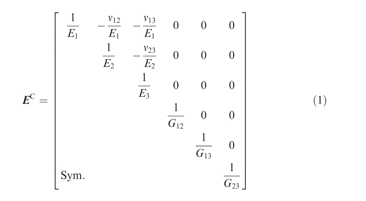
According to the generalised Hook’s law,the stiffness matrix D and compliance matrix ECare related as

Practically,the primary axis of blades is usually within a cone spanning up to 15°of the stacking line as shown in Fig.1.And the coordinate transformation of stress and strain between two Coordinate Systems(CS)is as follows:

where the subscript G and M denote the specimen and material coordinate systems,respectively;Tσand Tεare formulated as6

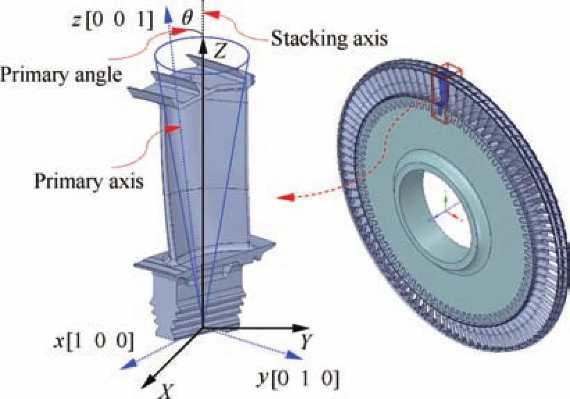
Fig.1 Material(x,y,z)and specimen(X,Y,Z)coordinate systems.
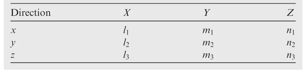
Table 1 Direction cosines.
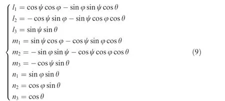
whereli,miandniare direction cosines between material-CS and specimen-CS of turbine blades.Moreover,the position of the material system(x,y,z)with respect to the specimen system(X,Y,Z)is determined by the direction cosines shown in Table 1.Therefore,when the alignment of two coordinate systems is not exactly parallel,the varied stiffness matrix,DG,is

For the description of two coordinate systems,we adopt the first kind of Eulerian angles,where the order of three involving rotations are:(A)the first rotation is by the angle ψ about theZaxis of specimen system;(B)the second rotation is by the angle θ aboutX′axis of the first rotated system;(C)the third rotation is by the angle φ aboutZaxis of the second rotated system,as shown in Fig.2.In Cartesian coordinate system,the transformation matrices with respect toZandXaxes are as follows12,13:

Fig.2 Eulerian angles involving three rotations.

where α is the generalised rotation angle with respect to the corresponding specified axis.With the stipulated Eulerian angles,the final rotation matrix R,can be achieved by multiplying the three order rotation transformation matrices as

In consequence,the direction cosines between two coordinate systems can be obtained as14
2.2.Modal properties of blades with arbitrary crystal orientations
The eigenproblem for turbine blades has the form:

where K and M are the stiffness and mass matrices of original turbine blades,i.e.the material-CS of turbine blades exactly parallels to specimen-CS; δK and δM are the perturbed matrices of stiffness and mass due to variation of material-CS with respect to specimen-CS;~Λ and~Φ are the eigenvalue and eigenvector matrices,correspondingly.Actually,the crystal orientation variation only has influence on the stiffness of blades,while the mass is constant.So,the perturbed matrix of stiffness is a function of varied angles while the perturbed matrix of mass is a full zero matrix,i.e.δK= δK(ψ,θ,φ),δM=0.
Practically,the turbine blades inevitably suffer from angle variation of crystal orientation,which leads to different stiffness perturbed matrices for arbitrary blade.The enhanced mode basis has been deliberately established to represent the modal properties of arbitrary turbine blades.Namely,the mode shapes of turbine blades with arbitrary crystal orientation can be approximately expressed as a linear combination of enhanced mode basis:

where c is the coefficient matrix of blade mode shapes expanded over the enhanced mode basis; Φj(j=1,2,···,n)is a set of mode shapes obtained by blades with different crystal orientations;ΦEis the notation of the enhanced mode basis.Substituting Eq.(11)into Eq.(10)and pre-multiplying the transposition of enhanced mode basis,the eigenproblem equation can be formulated as

where only the stiffness perturbed matrix δK,is unknown for arbitrary provided crystal orientations of turbine blades,when the eigenproblem is solved.
By the presented rotation way shown in Fig.2,CS&DS alloys are both transversely isotropic.It is explicit that the primary angle is equal to the second order rotation angle,θ,and the first and third order rotation angles,ψ and φ,describe the position of a cone with a conical angle,θ,and the rotation level,φ,around its primary axis.For the turbine blade with single crystal and directionally solidified alloys,the position of primary axis is critical and it primarily influences its mechanical behavior such as the natural frequencies,mode shapes,stress and strain,etc.Generally,to meet the properties of anisotropic blades and visualize the primary axis in a planar polar figure for convenience,the primary angle,θ,and its circumferential position,β,referenced toXaxis are presented.The circumferential position angle,β,under the introduced rotation order can be derived from Eq.(9)as

when we calculate the angle,β,the limit of angle from antitangent solution should be taken into account.The visualized figure of the primary axis description and notations is shown in Fig.3(a).In the picture,three red circles are presented and show primary axes of three blades.The primary angles,θ,and circumferential angles,β,in plane of these three blades are(5°,10°,and 15°)and(0°,120°,and 240°),respectively.Based on the visualization of primary angle position,the construction of enhanced mode basis,ΦE,is shown in Fig.3(b).Generally,the enhanced mode basis is constructed by a large number of mode sets of blades.Considering the requirements of accuracy and efficiency in calculation,the number of mode sets is usually truncated with optimal efficiency.Here the enhanced mode basis is constructed by a mode set obtained from the blade without any variation of primary axis and four mode sets obtained from the blade whose primary angle is 13°and uniformly distributed in the circumferential position,that is,the number of enhanced mode sets is 5,i.e.n=5 in Eq.(11).
2.3.Crystal orientation identification based on surrogate model and genetic algorithm
For convenience,Eq.(12)can be rewritten as

where Ko= ΦTEKΦE,δK=ΦTEδKΦEand M=ΦTEMΦEdenote the corresponding condensed matrix of original stiffness matrix,perturbed stiffness matrix and mass matrix of turbine blades respectively.The enhanced mode basis can be obtained from blades with crystal orientations shown in Fig.3(b).In addition,the enhanced mode basis is constant and can be used for arbitrary blades with any crystal orientation.So,Koand M are constant matrices for any case.In order to efficiently describe the condensed matrix of stiffness perturbation,the Kriging method15,16is introduced to approximate the condensed perturbed matrix δK.The dimension of δK depends on the modal truncation number,i.e.the total dimension is 5 times the modal truncation number for the construction of the enhanced mode basis as shown in Fig.3(b).So,it is efficient to perform the approximation of elements of matrix δK.Under the ordering of the defined Eulerian angles,only the first two angles(ψ,θ)are important for the dynamic characteristics of turbine blades,so the condensed perturbed matrix is formulated as

and moreover δK= [δK]T,so only the elements of upper/lower triangle of the condensed perturbed matrix need to be approximated.
When the surrogate model is constructed based on Kriging method for the condensed perturbed stiffness matrix δK,the employed design points are visualized in Fig.4.Because the elements of δK are complex functions of angles θ and β,the total number of design points is 361(i.e.the angles θ and β within the considered range are uniformly partitioned into 11 and 36 points),which can obtain enough accuracy for approximating the elements of the condensed stiffness perturbed matrix with higher efficiency.Consequently,for an arbitrary blade,the eigenproblem of Eq.(14)can be solved directly based on δK that is achieved from a surrogate model with the corresponding crystal orientation of this turbine blade.
For exactly identifying the crystal orientation with high efficiency,genetic algorithm is employed.17,18The modal information of blades is used to construct the fitness functions of genetic algorithm.The variations of modal properties obtained from Eq.(14)based on the surrogate model with respect to the unidentified structure are quantified as

where Freqiis the frequency of theith mode obtained from Eq.(14),i.e.searching from constructed surrogate model;freqiis the frequency of theith mode of an unidentified blade;mis the number of modal truncation;MACiiis the Modal Assurance Criterion(MAC)of theith mode between mode shapes obtained from Eq.(11)and from the unidentified blade.The MAC values can be obtained as19

whereiandjdenote the index of modes;φAand φBdenote the mode shapes of two compared structures respectively.
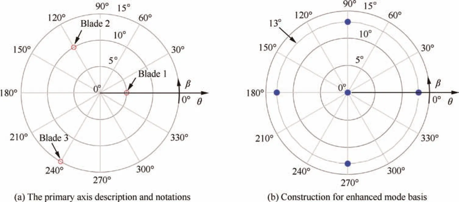
Fig.3 Plan visualization of primary axis position.

Fig.4 Crystal orientation distribution of design points for surrogate model construction.
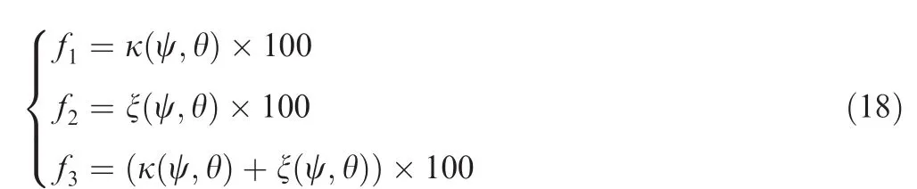
Consequently,considering the variations of modal properties between that achieved from Eq.(14)and from the unidentified blade,construction of three kinds of fitness functions for genetic algorithm is introduced and formulated as follows:
The procedure of crystal orientation identification based on surrogate model and genetic algorithm is described as follows:
(1)Construct the surrogate model based on Kriging method for condensed perturbed matrix of stiffness,δK.And,calculate the condensed matrices Koand M using enhanced mode basis with nominal/initial stiffness and mass matrices.
(2)Prepare the modal properties(frequencies and mode shapes)for unidentified structures.
(3)Optimize the fitness functions in Eq.(18)using genetic algorithm tool.The crystal orientation angles are identified when steady convergence emerges.
3.Numerical studies
3.1.Accuracy of enhanced mode representation and surrogate model
In this section,the accuracy of using an enhanced mode basis to represent the mode shapes of turbine blade with arbitrary crystal orientation and the description of the condensed perturbed matrix,δK,by using a surrogate model are demonstrated.In general,the first 30 modes are considered for calculation in this paper.The anisotropy material employed for numerical calculations is DZ12520,21and the employed blade model is shown in Fig.5.This turbine blade model has about 47000 Degrees of Freedoms(DoFs)and is meshed by Solid 187 in ANSYS.The boundary condition of the blade is set to be fixed at the root.
Accuracy of frequencies by using enhanced mode basis to express modes of arbitrary turbine blades is shown in Fig.6(a).From this picture,the maximum error of the first 30 modes is less than 0.0026%.The MAC values between the mode shapes derived from Eq.(11)and that from directly solving the finite element model of blade are plotted in Fig.6(b).The diagonal elements of MAC matrix are all equal to 1.It illustrates high accuracy of the proposed method by using an enhanced mode basis to linearly represent the mode shapes of arbitrary turbine blades with anisotropy materials.
In order to perform the modal analysis of Eq.(14)in high efficiency,Kriging method is introduced to construct a surrogate model for the elements of the condensed perturbed matrix δK.For visualizing the variation of elements of the condensed perturbed matrix with respect to the position of primary axis,θ and β,the variation distribution of the first element of matrix δK is shown in Fig.7.The variation values are normalized to the maximum component.The variation distribution of other elements of condensed perturbed matrix possesses the same complex varied properties.Actually,any element of δK has a surrogate model as shown in Fig.7,but the variation distribution is different when the upper/lower triangle of matrix is considered(because δK is a symmetric matrix).

Fig.5 Finite element model of employed turbine blade.

Fig.6 Accuracy of enhanced mode representation versus original finite element model.
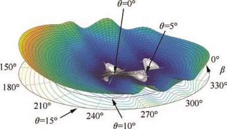
Fig.7 Normalized variation distribution of the 1st element of condensed perturbed stiffness matrix.
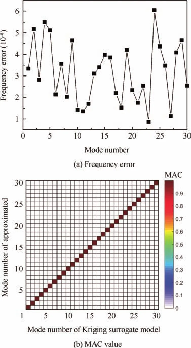
Fig.8 Accuracy of surrogate model versus original model.
In order to illustrate the accuracy of the surrogate model based on Kriging method,an example is employed.The surrogate model is constructed as the previously mentioned method.Frequencies obtained from the directly-condensed perturbed matrix with respect to those from the condensed perturbed matrix based on the surrogate model are compared and the corresponding errors are shown in Fig.8(a).It can be seen that the maximum error from the surrogate model is less than 6.0×10⁻⁶%,almost no error being introduced by employing the surrogate model.Furthermore,the MAC values corresponding to this case are shown in Fig.8(b).It is shown that all the diagonal components of MAC matrix are equal to 1.That is,both mode shapes obtained from the directly condensed perturbed matrix and from the condensed perturbed matrix based on the surrogate model are in good agreement.Therefore,the surrogate model based on Kriging method for the condensed perturbed matrix is demonstrated with high accuracy and efficiency and shows significant advantage for approximating the elements of the condensed perturbed matrix.

Fig.9 Convergences of fitness functions constructed by three different ways.
3.2.Examples of crystal orientation identification
The process of crystal orientation identification is based on the surrogate model and genetic algorithm.There into,surrogate model is employed to achieve the condensed perturbed matrix of stiffness for Eq.(14)of blades with arbitrary crystal orientation,while the genetic algorithm is used to search the optimal value of fitness functions.Comprehensively,constructions of three fitness functions are employed to separately identify the crystal orientation angles as Eq.(18).For options of genetic algorithm,the number of population is 50;the number of iteration is 15(because 15 iterations can achieve convergence for three kinds of fitness functions).Various optimizations below are discussed to investigate the identification capability of the proposed method by using different fitness functions:
(1)The fitness function only considers the variation of frequency as f1:From Eq.(18),four cases with different combinations of angles ψ and θ are discussed.Convergence curves of these four cases are plotted in Fig.9(a).Obviously,the fitness functions in four cases all converge to a steady value after 10 iterations.
(2)The fitness function only considers the percentage variation of MAC values as f2.The relationships between the fitness function value and the iteration number in four cases above are overlaid in Fig.9(b).It can be seen clearly that in all cases convergence is achieved after several or over ten iterative processes.
(3)The fitness functions,f1and f2,are both considered as f3:When considering both variation of frequencies and modal assurance criterion of mode shapes in the fitness function,the iterative process still converges in fourcases as shown in Fig.9(c).Clearly,when the number of iterations is equal to 15,four cases are all converged to a steady value.
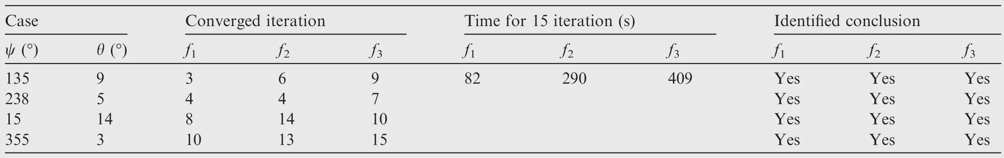
Table 2 Parameters of crystal orientation identification.
From Fig.9,it can be seen that the convergence rates among three different fitness functions are different.The fitness function only considering the frequency information converges in the fastest rate,while the one considering both frequency and mode shapes simultaneously converges slowly.In summary,identification results of these four cases are provided in Table 2.The fitness functions constructed asf1,f2andf3can exactly identify the crystal orientation angles,ψ and θ,although time consumption of these three fitness functions is quite different.The fitness function constructed based on the frequency variation is considered preponderant within 82 s for 15 iterations.
4.Conclusions
The method of enhanced mode basis has been developed to linearly express the mode shapes of arbitrary turbine blades with any crystal orientation variation of anisotropy materials.The proposed method can be utilized for blades with any stiffness perturbed matrix,with high accuracy and efficiency.
Surrogate model based on Kriging method has been introduced for solving the eigenproblem of blades with crystal orientation arbitrarily distributed.The solution is highly effective and efficient without any loss of accuracy.
Genetic algorithm has been employed to optimize the defined fitness functions,which were constructed by considering the variation of frequencies and correlation of mode shapes.The crystal orientation angles are identified according to the convergence curves of fitness functions.
A computer program for identification of crystal orientation for turbine blades with anisotropy materials has been developed.The accuracy and the computational efficiency of the proposed method have been demonstrated with a realistic turbine blade on several random cases.
There are still several issues that require further exploration.For example,an effective procedure of finite element modelling including the mesh quality and the trusted fixed conditions is required,and the experimental test to capture the effective modal information of turbine blades with anisotropy materials in order to validate the proposed method is also essential.Nowadays,the non-contact measurement,such as the scanning laser Doppler vibrometry,that is capable of measuring the natural frequencies and the detailed mode shapes of a structure in a fast way,looks very promising.The techniques of modeling error identification,model correlation and updating similarly show great potential to validate the practical application of the proposed method.The further research on these issues is currently underway and the results will be reported in another paper in the future.
Acknowledgements
This work was co-supported by the National Natural Science Foundation of China (Nos.51405460,11372128 and 51175244)and National Safety Academic Foundation of China(No.U1730129).The supports from the Collaborative Innovation Center of Advanced Aero-Engine,Jiangsu Province Key Laboratory of Aerospace Power System,the Key Laboratory of Aero-Engine Thermal Environment and Structure,Ministry of Industry and Information Technology are also gratefully acknowledged.
1.Manetti M,Giovannetti I,Pieroni N,Horculescu H,Peano G,Zonfrillo G,et al.The dynamic influence of crystal orientation on a second generation single crystal material for turbine bucketsASME turbo expo 2009:Power for land sea and air.2009.p.125–33.
2.Chang JC,Yun YH,Choi C.Failure analysis of gas turbine buckets.Eng Fail Anal2003;10(5):559–67.
3.Kiyak Y,Fedelich B,May T.Simulation of crack growth under low cycle fatigue at high temperature in a single crystal superalloy.Eng Fract Mech2008;75(8):2418–43.
4.Savage MWR.The influence of crystal orientation on the elastic stresses of a single crystal nickel-based turbine blade.ASME 2011 turbo expo:turbine technical conference and exposition.2011.p.37–46.
5.Kaneko Y.Study on vibration characteristics of single crystal blade and directionally solidified blade.ASME 2011 turbo expo:turbine technical conference and exposition.2011.p.931–40.
6.Arakere NK,Swanson GR.Effect of crystal orientation on fatigue of single crystal nickel base turbine blade superalloys.J Eng Gas Turb Power2000;124(1):161–76.
7.Sadeghi F,Kermanpur A,Sarami N,Heydari D,Nematollahi M,Bahmani M.A comparison on the EBSD and RO-XRD techniques for measuring crystal orientation of the singlecrystal Ni-based superalloys.Metallogr Microstruct Anal2016;5(4):1–8.
8.Ai C,Zhou J,Zhang H.Misorientation induced by withdrawal rate transition and its effect on intermediate temperature stress rupture properties of a Ni3Al based single crystal superalloy.J Alloys Compd2015;637:77–83.
9.Guo Z,Fu T,Fu H.Crystal orientation measured by XRD and annotation of the butter fly diagram.Mater Charact2000;44(4):431–4.
10.Petrov E,Ge´radin M.Finite element theory for curved and twisted beams based on exact solutions for three-dimensional solids part 2:anisotropic and advanced beam models.Comput Methods Appl Mech Eng1998;165(1–4):93–127.
11.Skrzypek JJ,Ganczarski AW.Mechanics of anisotropic materials.Berlin:Springer International Publishing;2015.
12.Slabaugh GG.Computing Euler angels from a rotation matrix.[Internet].[ctied 2017 September 7]1999;6(2000):1-6.Available from:http://gregslabaugh.name/publication/euler.pdf.
13.Piovan G,Bullo F.On coordinate-free rotation decomposition:Euler angles about arbitrary axes.IEEE Trans Robot2012;28(3):728–33.
14.Lesk†AM.On the calculation of Euler angles from a rotation matrix.Int J Math Educ Sci Technol1986;17(3):335–7.
15.Lophaven SN,Nielsen HB,Søndergaard J.DACE—A MATLAB Kriging toolbox—version 2.0.Kgs.Lyngby,Denmark:Technical University of Denmark;2002.Report No.IMM-REP-2002-12.
16.Couckuyt I,Forrester AI,Gorissen D.Blind Kriging:implementation and performance analysis.Adv Eng Softw2012;49(1):1–13.
17.Boussaid I,Lepagnot J,Siarry P.A survey on optimization metaheuristics.Inform Sci2013;237:82–117.
18.Konak A,Coit DW,Smith AE.Multi-objective optimization using genetic algorithms:a tutorial.Reliab Eng Syst Saf2006;91(9):992–1007.
19.Pastor M,Binda M,Harcarik T.Modal assurance criterion.Procedia Eng2012;48(1):543–8.
20.Hu XA,Yang XG,Shi DQ,Yu HC,Ren TT.Constitutive modelling of a directionally solidified nickel-based superalloy DZ125 subjected to thermal mechanical creep fatigue loadings.Rare Met2016,p.1–15.
21.Hu XA,Yang XG,Shi DQ,Yu HC.Out of phase thermal mechanical fatigue investigation of a directionally solidified superalloy DZ125.Chin J Aeronaut2016;29(1):257–67.
杂志排行

CHINESE JOURNAL OF AERONAUTICS的其它文章
- A self-similar solution of a curved shock wave and its time-dependent force variation for a starting flat plate airfoil in supersonic flow
- Robust Navier-Stokes method for predicting unsteady flowfield and aerodynamic characteristics of helicopter rotor
- Effects of trips on the oscillatory flow of an axisymmetric hypersonic inlet with downstream throttle
- Development of a coupled supersonic inlet-fan Navier–Stokes simulation method
- An equilibrium multi-objective optimum design for non-circular clearance hole of disk with discrete variables
- Shock/shock interactions between bodies and wings