Robust Navier-Stokes method for predicting unsteady flowfield and aerodynamic characteristics of helicopter rotor
2018-03-21QijunZHAOGuoqingZHAOBoWANGQingWANGYongjieSHIGuohuaXU
Qijun ZHAO,Guoqing ZHAO,Bo WANG,Qing WANG,Yongjie SHI,Guohua XU
National Key Laboratory of Rotorcraft Aeromechanics,Nanjing University of Aeronautics and Astronautics,Nanjing 210016,China
1.Introduction
The accurate and rapid prediction of rotor flowfield is essential for aerodynamic performance analysis of rotor,and further high-performance rotor design.Though the Computational Fluid Dynamics(CFD)methods have been widely used for fixed wing aircraft,the prediction of rotor flow field by CFD method is still one of the most complex and challenging problems in helicopter aerodynamics.It is because unsteady flowfield of rotor is characterized by strong non-linear and threedimensional effects,and there are different types of flow separation phenomena due to shock-boundary layer interaction on advancing blade and unsteady dynamic stall on retreating blade.1Additionally,the shedded vortical wakes and strong blade-tip vortices further increase the complexity and difficulty for simulating the unsteady flow field of rotor.2These problems require that the CFD methods have high accuracy on simulating the flow separation and vortical wake of rotor.
Till now,there are a few CFD codes developed specifically for helicopter rotor analysis.DLR and ONERA developed a common3European Euler code EROS for simulating flow field of rotor.Although the EROS code is a valid platform with a high growth potential,it has not yet met all of the industrial requirements.It is because Euler equations ignore the viscous fluxes in the Navier-Stokes equations,resulting in losses of capabilities in predicting large flow separations on retreating side of rotor,and in calculating performance parameters due to missing of viscous frictions.Using the Navier-Stokes equations,and together with free-wake method,NASA Ames research center established a rotor flow field code known as TURNS,and the numerical results demonstrated the capabilities of this hybrid CFD methodology in calculating helicopter rotor aerodynamic flow field in both hover and forward flight.4Nevertheless,since TURNS considered a thin-layer approximation and employed an algebraic turbulence model to obtain estimates of eddy viscosity for calculating turbulent flows,it is hard to capture large flow separation when rotor is operated in large maneuver flight.By considering these problems,NASA had developed an OVERFLOW-D code for predicting flowfield of rigid blade rotor.OVERFLOW-D was based on‘OVERFLOW” solver,and solutions were computed on structured and moving-embedded grids.5The code’s ability had been demonstrated to match experimentally measured Figure of Merit(FM)in Ref.6Furthermore,a multi-function code called Helios is designed specifically for rotorcraft analysis.7,8It contains unstructured near-body Reynolds-Averaged Navier-Stokes(RANS)solver and Cartesian off-body Euler solver,and the RANS equations are solved by second-order spatial accuracy and Spalart-Allmaras(S-A)turbulence model.Though the unstructured-grid techniques could address the specific challenges of rotor flow field to accurately resolve the rotor wake tip vortices,they are viewed as either too complicated or too costly compared with structured-grid techniques.Additionally,a turbulence model more suitable for rotor flowfield should be used,and high order spatial accuracy should be employed to further improve the precision of prediction of rotor aerodynamic performance.
In the present investigation,a robust Chinese Laboratory of Rotorcraft Navier-Stokes(CLORNS)equations code is established to predict the complex unsteady aerodynamic characteristics of rotor,based on moving-embedded grid technology and an earlier Navier-Stokes/full potential/free wake hybrid method proposed by the author.9–13In the improved code,to generate the structural body-fitted grids around a rotor blade with complex shape a parameterized method is established based on solution of Poisson equations.Considering the periodically flapping and pitching motions of rotor blade,a Disturbance Diffraction Method(DDM)for holecell identifying and a Minimum Distance Scheme of Donor Elements(MDSDE)strategy for donor elements searching are proposed with high efficiency and universality.Aimed at improving the computational efficiency and accuracy,both the explicit Runge-Kutta and implicit LU-SGS method are available for solving Unsteady Reynolds-Averaged Navier-Stokes(URANS)equations,and there are three alternative spatial accuracy schemes in the code,i.e.second-order central difference scheme,third-order Roe-MUSCL scheme,and fifthorder WENO-Roe scheme.At the same time,adaptive grid technology has been employed in this code.To further improve the flowfield prediction efficiency,MPI parallel method based on subdivision of grid,local preconditioning method and Full Approximation Storage(FAS)multi-grid method are developed in the code.Additionally,the present code provides interfaces with the Computational Structural Dynamics(CSD)analyses and rotor aeroacoustics analyses modules.
2.Computational methods
2.1.New moving-embedded grid technology
According to the complex geometry of rotor blade,a parameterized body-fitted grid generation method is established by inputting distributions of section airfoils,chord length,quarter-chord line and twist of blade.Firstly,a series of typical blade sections are chosen,and body-fitted grids around some typical airfoils are generated by solving Poisson equations.Then,grids around the whole blade are generated by interpolation between blade typical sections and folding at blade root and tip.Finally,considering chord length,quarter-chord line and twist distributions of blade,grid refinement is quickly fulfilled by solving the Poisson equations.Fig.1 shows the grids around rotor blade and the whole moving-embedded grid system of rotor.
The periodic motions of blade,such as flapping and pitching,make it difficult to identify the hole-cells in the Cartesian background grids.In order to improve the computational efficiency of rotor flowfield simulation,several methods14,15were established to accomplish the identification of hole-cells.Based upon the ‘Top map” method proposed in Ref.14,and aimed at accurately identifying hole-cells along any complex envelope,a universal method is established in the CLORNS code named DDM.16The detailed process of this method could be described as:

Fig.1 Moving-embedded grid system around rotor.
(1)Specifying an arbitrary and closed envelope,and the cells along this envelope are marked as hole boundary cells(the red cells shown in Fig.2)if the envelope passes across them.
(2)Choosing an original disturbance source cell outside the marked hole(numbered as 1 in Fig.2).
(3)Judging the adjacent cells of disturbance source in two categories:(A)if the cell is neither a hole boundary cell nor adjacent to any hole boundary cell,set it one of the new disturbance source cells;(B)if it is not a hole boundary cell but adjacent to the hole boundary,mark it as an artificial inner boundary cell of background grids.
(4)Fulfilling the procedure until there is no new disturbance source cell,and a closed artificial inner boundary of background grids could be determined(cells with green number in Fig.2).
A Pseudo-Searching Scheme of Donor Elements(PSSDE)method had been proposed in Ref.8based upon the Inverse-Map.Further considering the time consuming regeneration of Inverse-Map around an aeroelastic blade,a MDSDE method is proposed in this work.16The key point of this new method is to find out the grid pointO(O1orO2in Fig.2,for example)with minimum distance to a pointPon background grid(P1andP2in Fig.2,for example),and then donor cell ofPcould be quickly found out within rotor grid cells containingO.The detailed process of this method could be described as:
(1)Selecting the start pointSof the rotor blade grids,just as shown in Fig.2.
(2)Calculating the distances of adjacent point ofSto the pointP,finding the point with minimum distance and marking as new start point.
(3)Cycling the process 2 until finding the grid pointO.
(4)Judging the pointPin background grids belong to the blade grid around pointO,and marking this grid as the donor cell ofP.
(5)Finding the donor cell ofPon the blade grid which is around the pointO,and marking the number of this cell.

Fig.2 Schematic diagram of DDM and MDSDE methods.
Finally,the moving-embedded grid system containing holecells and donor cells of artificial inner boundary is shown in Fig.1.
2.2.Flowfield solver
In the CLORNS code,the URANS equations are employed as governing equations for simulating the flowfield of rotorcraft.

where W is the conservation variable,Fcand Fvare the modified-convective flux and viscous flux respectively,tis physical time,Ω is the volume of grid cell,andAis the boundary of grid cell.Considering the contravariant velocityVtof cell surface and original convective flux Fc,0,Fccan be written as

2.2.1.Spatial discretization scheme
To accurately predicting the non-linear and unsteady characters of vortical flowfield of rotor,the third-order Roe scheme17and AUSM+type method18together with MUSCL and WENO approaches are employed for the discretization of convective fluxes.The numerical flux on the cell faces calculated by Roe scheme is given by


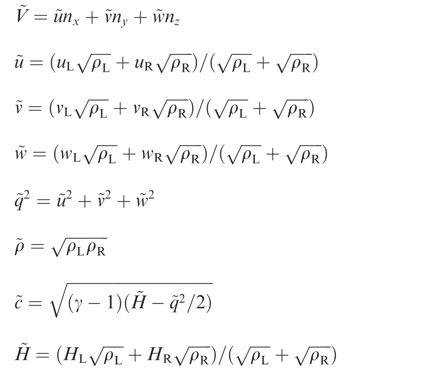
The AUSM+type method divides the convective fluxes into pressure terms and convective terms,and the discretization can be written as
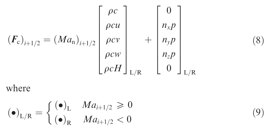
Marepresents the Mach number of the control volume,(Man)i+1/2represents the Mach number normal to the face of the control volume,and it could be expressed as

The pressure at the face of the control volume can be obtained from the splitting:

The third-order MUSCL interpolation and fifth-order WENO interpolation are used to reconstruct the left and right states across a cell interface.The reconstruction comes in the projection stage of the primitive variables,i.e.[ρ,u,v,w,p]T.
The third-order MUSCL scheme can be expressed by

where φ represents the limiter,the parameter κ determines the spatial accuracy of the interpolation,and the Van Albada limiter is used in the reconstruction;Qirepresents the flow variables,and Δ±can be expressed as

For the fifth-order WENO scheme,a 6-point stencil for the interpolation of the left and right states is needed,which is shown in Fig.3.
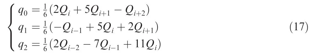
Fig.4 shows the stencils for the interpolation of left state quantities and it can be defined by

where ωirepresent the nonlinear weights,andqican be expressed as
Aimed at well simulating separated airflow over surface of rotorcraft,three alternative turbulence models are employed to calculate turbulence viscosity,and they are algebraic Baldwin-Lomax(B-L)model,19one equation Spalart-Allmaras(S-A)model,20,21andk-ω Shear Stress Transport(SST)model.To accurately capture the vertical wake of rotor,an adaptive grid strategy is applied to the Cartesian background grids.22
2.2.2.Temporal discretization method
In order to predict the unsteady flowfield of rotor,the dualtime method is employed to solve the temporal discretization.Eq.(1)can be rewritten as discrete form:

where Δtdenotes the global physical time step.In order to solve Eq.(18),we can use a time-stepping methodology which could be written as
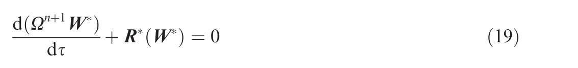
where W*is the approximation for Wn+1,τ represents pseudo time variable,and the unsteady residual is defined as

Fig.3 Schematic of interpolation for fifth-order WENO scheme.

Fig.4 Schematic of stencils for interpolation of left state quantities.
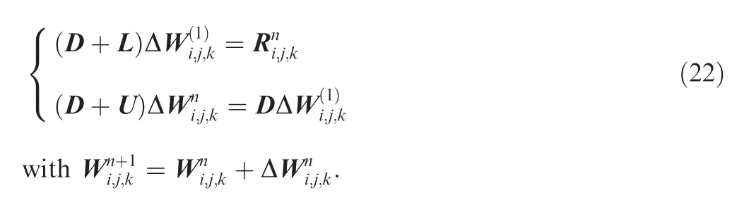
The sub-iteration is fulfilled by the implicit LU-SGS method which can be implemented easily on vector and parallel computers.23The temporal discretization of the Navier-Stokes equations can be written as

The factors are constructed so that L consists only of terms in the strictly lower triangular matrix,U of terms in the strictly upper triangular matrix,and D of diagonal terms.It is important to remark that the number of factors remains still the same independent of the number of space dimensions.
The system matrix of the LU-SGS scheme can be inverted in two steps:a forward and a backward sweep,i.e.
2.2.3.High-efficiency algorithms
In order to further improve the efficiency of the CFD method,the FAS multi-grid method is used on the rotor grid.24The variable in coarse grid is interpolated by the solution of fine grid,i.e.


where the forcing function (QF)2his

After several time steps carried out on the coarse grid,the coarse grid correction is given by

Hence,the new solution on the fine grid could be expressed by

Considering that the incompressible flow near blade root might slow down the convergence of RANS solver,and to address the problem,a preconditioning method is established by using the Pletcher-Chen25and Weiss-Smith preconditioned matrix.26The Navier-Stokes equations in 1D Euler equations could be expressed as

Additionally,the MPI parallel procedure is conducted to divide the moving-embedded grid system to several parts which will be individually calculated on a single CPU,and the parallel computing can significantly improve the efficiency of the CLORNS code.
2.2.4.CFD/CSD coupling
In order to obtain accurate rotor airloads,the CFD and CSD codes are mutually dependent in rotor unsteady airloads prediction.The CSD module is developed based on Hamilton’s variational principle:

where δUis the variation of strain energy,δTis the variation of kinematic energy,and δWis the virtual work done by external forces which is aerodynamics loads in this case.In order to improve the dynamics characteristics prediction accuracy of rotors with advanced blade tips,multiple beam elements are used for blade-tip modeling.The modified tip beam element could be expressed as
The discrete equations of motion(Eq.(31))for each element are assembled to form the blade equations of motion.These equations are then solved by using Newmark-Beta method to obtain the blade structural deflection affected by aerodynamic forces,which can either come from lifting-line theory or computational fluid dynamics solver.

where [Mi], [Ci], [Ki],Fiare the element mass,damping,stiffness matrix and force vector,respectively.
The flowchart of CLORNS code,including generation of embedded grid system around rotor,division of grid system for parallel computing,generation of moving-embedded grid,and multi-grid calculation of RANS solver,is shown in Fig.5.
3.Applications of CLORNS code
3.1.Vortical wake of rotor
The ‘Lynx” experimental rotor is taken as validation case for prediction of vortical wake of rotor.27The hover condition with a collective pitch of 15°,and blade-tip Mach numberMatip=0.56 is conducted for the test case.
Fig.6 illustrates the vorticity contours on original and adaptive background grids.As can be seen,the computing accuracy on calculating blade tip vortices is significantly improved with grid adaption.Additionally,with Cartesian grid adaption,an expansion trend after initiating contraction of the vortical wake could be captured.

?
Fig.7(a)and(b)shows the predicted trajectories of the tip vortex in vertical and radial directions respectively,along with comparisons to the experimental data and free wake simulated results from Ref.28,where,y/Rrepresents the relative position,and ψ represents the azimuthal angle.It can be seen that the vertical and radial displacements of the tip vortex simulated by CLORNS code by adaptive grid technology correlate better with the experimental data for a wake age up to 360°.

Fig.6 Vorticity contours based on adaptive grid technology.
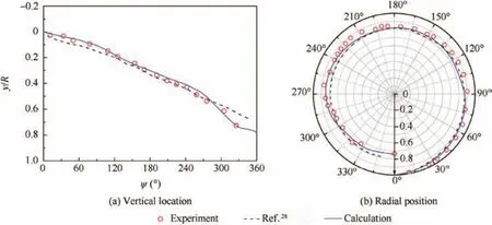
Fig.7 Tip vortex location of Lynx experimental rotor.
3.2.Aerodynamic characteristics of rotor in hover
The UH-60A is a four-bladed rotor with aspect ratio of 15.3,and consists of advanced rotor airfoils of SC1095 and SC1095R8.The blades have non-linear twist and 20°sweepback tip.For the validation case,the hover condition with a collective pitch of θ=9°and blade-tip Mach numberMatip=0.628 is selected.29
Fig.8 is the comparison of calculated pressure coefficientCpwith the test data,wherer/Rrepresents the radial location of blade,andx/crepresents the chordwise location of airfoil.The results are calculated by employing S-A and B-L turbulent model.As can be seen,both results simulated by B-L model and S-A model have good agreement with the test data,and the result calculated by S-A model is better than that by B-L model,because the one equation S-A model could better simulate flow separation than B-L model near blade tip.

Fig.8 Pressure coefficients of UH-60A rotor.
Fig.9 further shows the simulated performance curves of UH-60A rotor,such as FM varied against rotor thrust coeffi-cientCT/σ and lift coefficientCLalong rotor blade.The values of FM calculated by S-A model have good agreement with the test data.Similarly,the lift coefficients along rotor blade calculated by S-A model are much more comparable to the test data,and between themselves,nevertheless some differences are encountered throughout the blade especially the results simulated by B-L model.

Fig.9 Performance of UH-60A rotor in hover.
The vorticity contour lines of the UH-60A rotor at the collective pitch angle of 12°with|▽ × V|=0.12 are shown in Fig.10,where B1 represents the first blade,and E represents the end of the blade-tip vortex.It is illustrated that the blade-tip vortex structure simulated by Jameson-Schmidt-Turkel(JST)scheme is not complete,and the vortex sheds about 115°until it dissipates completely.On the contrary,the blade-tip vortex simulated by Roe-WENO scheme sustains to 280°before it dissipates completely,and the vortex structure is more obvious compared with the vortex simulated by JST scheme.
The vorticity at the azimuthal angle of 0°is shown in Fig.11,and the vortex numbers captured by different spatial discretization schemes are 1(JST scheme),2(Roe-MUSCL scheme)and 3(Roe-WENO scheme),respectively.As a result,it is indicated that the numerical dissipation of the Roe-WENO scheme is the lowest compared with that of JST scheme and Roe-MUSCL,and as a result,it could simulate the vortex flowfield of the rotor more accurately.
3.3.Aerodynamic characteristics of rotor in forward flight
3.3.1.Helishape 7AD rotor dynamic stall
The helishape 7AD rotor with new type tip shape(dihedral and sweep)is taken as validation case,the rotor operates with rotational tip Mach numberMatip=0.617,advance ratio μ =0.41,and rotor shaft tilt angle αs=-11.8°,and the trimmed periodic pitching and flapping angle are:

Fig.10 Comparison of vorticity contour lines among different spatial discretization schemes(|▽ ×V|=0.12).

Fig.11 Comparison of vorticity among different spatial discretization schemes at azimuth of 0°.

Fig.12 shows the normal lift coefficient(CnMa2)at different blade sections,and the calculated results are compared with the test data and the reference results of Ref.29As can be seen,the numerical results obtained by the CLORNS as well as the reference value agree with the test data.However,it can be noticed that some deviations still exist between numerical results and experimental data.This reason may be due to the fact that the viscosity of flowfield cannot be accurately simulated by URANS equations.To overcome this insufficient,new numerical methods,such as DES and LES,should be employed in the simulation of rotor flowfield in the near future.
Fig.13 illustrates the variation of normal forceCnMa2with pitching and flapping motions of rotor atr=0.7Rblade section,where the arrows in the figure imply the motion direction of rotor,and the symbol‘°”in the figure denotes the angle of attack.As shown inxOzplane in this figure,there are local minimum values ofCnMa2at about 90°and 270°azimuth angles,where the flapping angle of rotor is in an average value.At the same time,there are local maximum values ofCnMa2when the flapping angle of rotor is minimum or maximum(0°or 180°azimuth angle).As can be seen from theyOzplane,there are local minimum values ofCnMa2when the pitching angle of rotor is minimum or maximum,and there are local maximum values ofCnMa2when the pitching angle of rotor is in its average value.Additionally,Fig.14 shows the relationship betweenCnMa2and pitching and flapping angle of rotor at different blade sections.At different blade sections,though the locations of minimum and maximum values ofCnMa2are somewhat different,the variational trend is similar to that atr=0.7Rblade section.
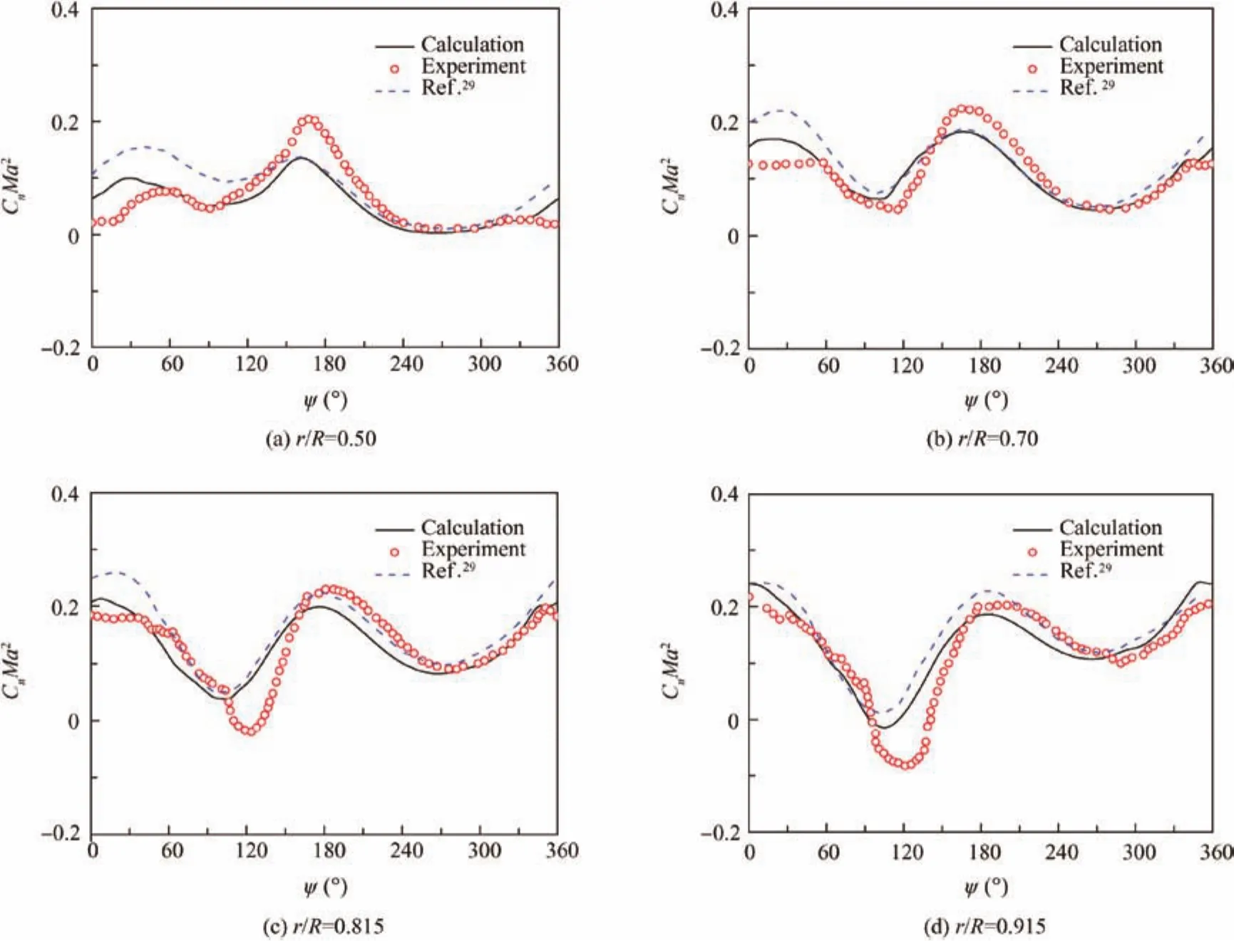
Fig.12 Comparison of CnMa2at different sections of helishape 7AD rotor.

Fig.13 Variation of normal lift coefficient with rotor flap and pitch at r=0.7R section.

Fig.14 Variation of CnMa2at different blade sections with rotor flap and pitch.
3.3.2.UH-60A rotor
The aerodynamic characteristics of UH-60A rotor in forward flight are also simulated by the CLORNS code.The numerical results are obtained by employing rigid rotor and CFD/CSD30–32coupling method.The UH-60A under C8534 state is taken as numerical example,the rotor operates with rotational tip Mach numberMatip=0.642,advance ratio μ=0.368,rotor shaft tilt angle αs=-7.31°and nominal thrust coefficientCT/σ=0.084.
Fig.15 shows the comparison among the experimental data,CLORNS numerical results(including rigid blade results(M1)and CFD/CSD coupled results(M2)),and calculated results from Ref.31(M3)in terms ofCnMa2versus the azimuthal position ψ.In Ref.31,the results are achieved by OVERFLOW-D/CAMRAD software.Here the comparisons show overall a higher prediction of normal force coefficient calculated by CLORNS_CSD code than rigid blade method.
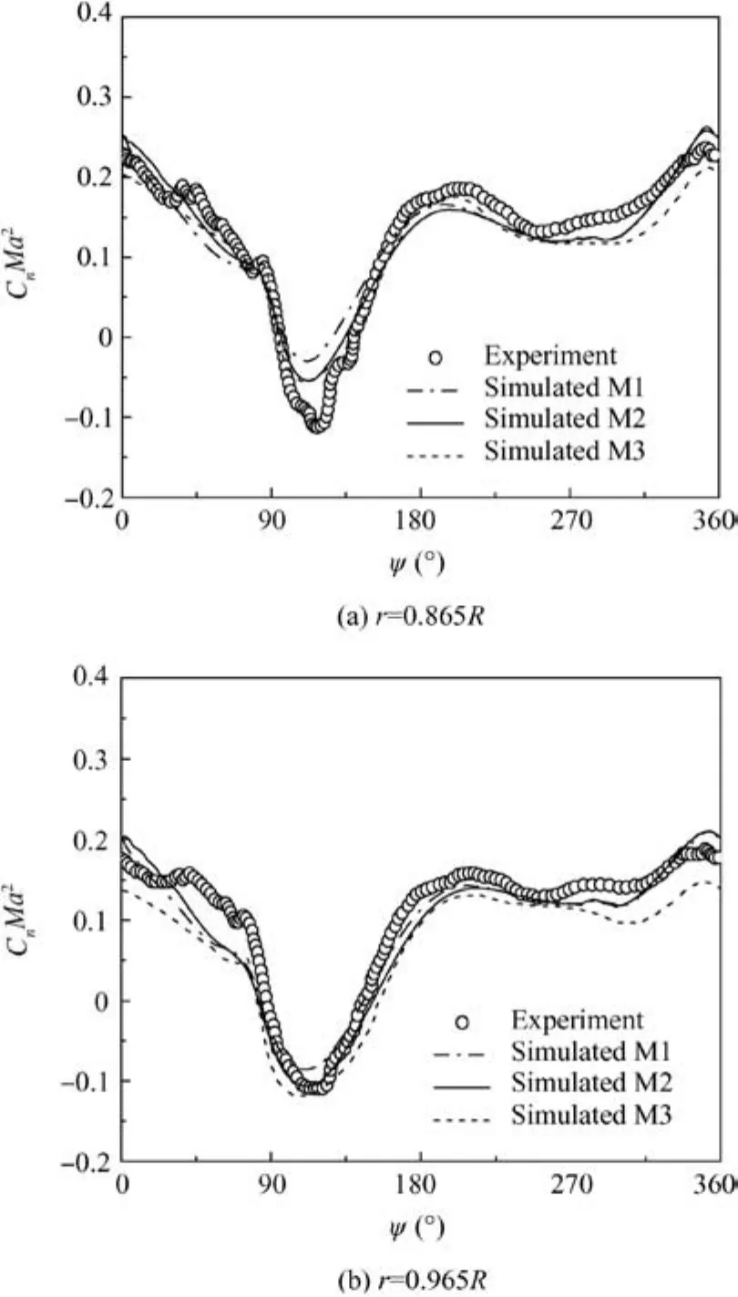
Fig.15 Comparison of CnMa2on four-bladed UH-60Arotor between numerical results and experimental data.
4.Conclusions
(1)The CLORNS code has been developed for the prediction of the unsteady flowfield of helicopter rotors in this work.In order to improve the computational efficiency,the DDM method and the MDSDE method are established and coupled in the moving-embedded grid system to accomplish the blade motions of rotation,flapping and pitching.
(2)The comparison of the simulated results indicates that the Roe-WENO scheme has the characteristic of lower numerical dissipation compared with the scheme of JST and Roe-MUSCL used in the simulation of the helicopter rotor flowfield,and it could predict the characteristics of blade-tip vortex more accurately.
(3)By comparing the simulated results of free wake method,it is indicated that the CFD method could simulate the blade-tip vortex more accurately.Meanwhile,the present CFD code also has high accuracy and efficiency for the simulation of unsteady aerodynamic characteristics and performance of helicopter rotor.
(4)In order to expand the applicable range,the CLORNS code provides modules of CFD/CSD analyses of helicopter rotor,and the numerical results indicate that the present code has high accuracy in aerodynamic loads simulation of helicopter rotor.
Acknowledgements
This study was co-supported by the National Natural Science Foundation of China (Nos.11272150,10872094 and 10602024).
1.Yeo H,Johnson W.Assessment of comprehensive analysis calculation of airloads on helicopter rotors.J Aircraft2005;42(5):1218–28.
2.Vieira BAO,Maughmer MD.An evaluation of dynamic stall onset prediction methods for rotorcraft airfoil design.Reston:AIAA;2013.Report No.:AIAA-2013-1093.
3.Renzoni P,D’Alascio A,Kroll N.EROS-a common European Euler code for the analysis of the helicopter rotor flow field.Progr Aerosp Sci2000;36(5–6):437–85.
4.Srinivasan GR,Raghavan V,Duque EPN.Flow field analysis of modern helicopter rotors in hover by Navier-Stokes method.J Am Helicopt Soc1993;38(3):3–13.
5.Chan W,Meakin R,Potsdam M.CHSSI software for geometrically complex unsteady aerodynamic applications.Reston:AIAA;2001.Report No:AIAA-2001-0593.
6.Strawn RC,Djomehri MJ.Computational modeling of hovering rotor and wake aerodynamics.J Aircraft2002;39(5):786–93.
7.Sankaran V,Sitaraman J,Wissink A.Application of the helios computational platform to rotorcraft flow fields.Reston:AIAA;2001.Report No:AIAA-2010-1230.
8.Sitaraman J,Potsdam M,Wissink A.Rotor loads prediction using Helios:a multisolver framework for rotorcraft aeromechanics analysis.J Aircraft2013;50(2):478–93.
9.Zhao QJ,Xu GH,Zhao JG.New hybrid method for predicting the flow fields of helicopter rotors.J Aircraft2006;43(2):372–80.
10.Zhao QJ,Xu GH,Zhao JG.Numerical simulations of the unsteady flow field of helicopter rotors on moving embedded grids.Aerosp Sci Technol2005;9(2):117–24.
11.Zhao QJ,Xu GH.A study on aerodynamic and acoustic characteristics of advanced tip-shape rotors.J Am Helicopt Soc2007;52(3):201–13.
12.Shi YJ,Zhao QJ,Fan F,Xu GH.A new single-blade based hybrid CFD method for hovering and forward- flight rotor computation.Chin J Aeronaut2011;24(2):127–35.
13.Wang B,Zhao QJ,Xu GH,Ye L,Wang JY.Numerical analysis on noise of rotor with unconventional blade tips based on CFD/Kirchhoff method.Chin J Aeronaut2013;26(3):572–82.
14.Wang B,Zhao QJ,Xu G,Xu GH.A new moving-embedded grid method for numerical simulation of unsteady flow field of the helicopter rotor in forward flight.Acta Aerodynam Sin2012;30(1):14–21[Chinese].
15.Yang WQ,Song BF,Song WP.Distance decreasing method for con firming corresponding cells of overset grids and its application.Acta Aeronaut Astronaut Sin2009;30(2):205–12[Chinese].
16.Zhao GQ,Zhao QJ,Wu Q.A universal moving-embedded grid method for CFD simulations of unsteady aerodynamic characteristics of rotor.J Aerosp Power2015;30(3):546–54[Chinese].
17.Edwards JR,Franklin RK,Liou MS.Low-diffusion flux-splitting methods for real fluid flows with phase transitions.AIAA J2000;38(9):1624–33.
18.Liou MS,Chang CH,Nguyen L,Theofanous TG.How to solve compressible multi fluid equations:a simple,robust,and accurate method.AIAA J2008;46(9):2345–56.
19.Baldwin B,Lomax H.Thin-layer approximation and algebraic model for separated turbulent flows.Reston:AIAA;1978.Report No:AIAA-1978-0257.
20.Spalart SR,Allmaras SA.A one-equation turbulence model for aerodynamic flows.Reston:AIAA;1992.Report No:AIAA-1992-0439.
21.Ashford G.An unstructured grid generation and adaptive solution technique for high-Reynolds-number compressible flows.Comput Electr Eng1996;41(6):68–85.
22.Ye L,Zhao QJ,Xu GH.An adaptive unstructured embedded mesh methodology suitable for the calculation on the rotor vortex flow field.Acta Aerodynam Sin2010;28(3):261–6[Chinese].
23.Sharov D,Nakahashi K.Low speed preconditioning and LU-SGS scheme for 3D viscous flow computations on unstructured grids.Reston:AIAA;1998.Report No:AIAA-1998-0614.
24.Melnik R,Mead H,Jameson A.A multi-grid method for the computation of viscid/inviscid interaction on airfoils.Reston:AIAA;1983.Report No:AIAA-1983-0234.
25.Pletcher RH,Chen KH.On solving the compressible Navier-Stokes equations for unsteady flows at very low Mach numbers.Reston:AIAA;1993.Report No:AIAA-1993-3368.
26.Weiss J,Smith WA.Preconditioning applied to variable and constant density flows.AIAA J1995;33(11):2050–7.
27.Light JS.Tip vortex geometry of a hovering helicopter rotor in ground effect.J Am Helicopt Soc1993;38(2):34–42.
28.Srinivasan GR,Baeder JD,Obayashi S.Flow field of a lifting rotor in hover–a Navier-Stokes simulation.AIAAJ1992;30(10):2371–8.
29.Wang JY,Zhao QJ.Effects of structural properties on rotor airloads prediction based on CFD/CSD coupling method70th American Helicopter Society international annual forum,2014.p.1515–26.
30.Wang JY,Zhao QJ,Xiao Y.Calculations on aeroelastic loads of rotor with advanced blade-tip based on CFD/CSD coupling method.ActaAeronautAstronautSin2014;35(9):2426–37[Chinese].
31.Potsdam M,Yeo H,Johnson W.Rotor airloads prediction using loose aerodynamic/structural coupling.JAircraft2006;43(3):732–42.
32.Shi Y,Xu Y,Xu G,Wei P.A coupling VWM/CFD/CSD method for rotor airload prediction.Chin J Aeronaut2017;30(1):204–15.
杂志排行

CHINESE JOURNAL OF AERONAUTICS的其它文章
- A self-similar solution of a curved shock wave and its time-dependent force variation for a starting flat plate airfoil in supersonic flow
- Effects of trips on the oscillatory flow of an axisymmetric hypersonic inlet with downstream throttle
- Development of a coupled supersonic inlet-fan Navier–Stokes simulation method
- An equilibrium multi-objective optimum design for non-circular clearance hole of disk with discrete variables
- Shock/shock interactions between bodies and wings
- Modeling and control for cooperative transport of a slung fluid container using quadrotors