Development of a coupled supersonic inlet-fan Navier–Stokes simulation method
2018-03-21QiushiLIYongzhaoLYUTianyuPANDaLIHananLUYifangGONG
Qiushi LI,Yongzhao LYU,Tianyu PAN,*,Da LI,Ha’nan LU,Yifang GONG
aNational Key Laboratory of Science and Technology on Aero-Engine Aero-Thermodynamics,Beihang University,Beijing 100191,China
bSchool of Energy and Power Engineering,Beihang University,Beijing 100083,China
cCollaborative Innovation Center of Advanced Aero-Engine,Beihang University,Beijing 100083,China
dGL-Turbo Compressor Company,Wuxi 214106,China
1.Introduction
Over the last decades,Computational Fluid Dynamics(CFD)has been well developed,which can accurately simulate the flow field of the turbomachinery and revolutionize the aerodynamic design process of propulsion system components.Full annulus multi-row unsteady calculations through the turbomachinery subject to non-axisymmetric flow can be calculated directly to resolve effects of separations close to the walls on the compressor characteristic,which in some cases is the center of concern.For instance,the Hybrid Wing-Body(HWB)aircraft is extremely concerned lately,which is an alternative concept for the conventional tube-and-wing aircraft.1In the design process,it involves coupled calculations of the inlet and full-annulus fan blades,and it is important to include the effect of fan blades on the inlet and nozzle design.A direct coupling of the inlet and full-annulus fan blades in the computational domain is more realistic and accurate for the inlet-fan interaction,but the demand for the computer resources is prohibitively large,including the memory and the CPU time,and more than tens of flow simulations are usually required.2To save the computer resources,some CFD studies were conducted using conventional uniform-back-pressure boundary condition at the fan face to simulate flow for propulsion-airframe integration problems.3–5However,for integration problems with highly distorted flows at the fan faces,the assumption of uniform static pressure may not be valid.By implementing an actuator disk with a Navier–Stokes code,it is possible to simulate the flow field through fan blades without the actual blade geometry.6However,based on the two-dimensional assumption,the actuator disk model does not include the effect of swirl and requires the total pressure and total temperature change across the fan as input terms.Recently,the passage averaged body force model has been an alternative to simulating the effect of blockage,swirl,and suction due to fan blades with reasonable computing costs.7–9This approach uses body force terms to model flow turning and loss due to rotor/stator blade rows.The body force terms,extracted from single-passage Navier-Stokes flow simulation results or experimental test data,were added as source terms in the flow equations for grid cells swept by blade rows.The body force approach allows relatively accurate flow simulations of inlet-fan interaction problems without actual full-annulus simulation of the rotor/stator geometry.Xu10developed a viscous body force model,which extracted viscous body forces as source terms form unsteady Reynolds Averaged Navier-Stokes(RANS)solutions and directly solved Euler equations through blade passages.Chima11introduced a three-dimensional unsteady CFD code called CSTALL to solve the Euler equations through the entire annulus and all blade rows.And two computational fluid dynamics codes have been merged to permit rapid calculations of subsonic inlet-fan interaction.7,12However,It needed a third code called SYNCEX to handle data communication,storage,and synchronization.So,this method made it relatively complicated for the data transfer between CFD codes.In addition,it was also inconvenient to generate complicated geometry and mesh for subsonic inletfan calculations.
In the present study,a coupled supersonic inlet-fan Navier–Stokes simulation method was developed using COMSOL–CFD code.The COMSOL Multi-physics software environment is capable of facilitating all steps in the modeling and simulation processes from part defining,feature based meshing to visualization and solution analysis.The inlet and fan could been simulated simultaneously by different COMSOL modules,and the data transfer at each grid point of the inlet-fan interface was completed more easily by the form of boundary conditions than the SYNCEX code.7,12A three-dimensional body force model,in which viscous effects on the exchange of momentum between fluids and detailed viscous flow close to walls in blade passages can be calculated directly,was installed into the Navier–Stokes code of the COMSOL-CFD to simulate blade rows without specifying blade geometry.The governing equations for flow were written in nonconservative form in Cartesian coordinates with body forces as source terms on the right-hand side.Because the body force only changed the size of the mechanical energy with nothing on the size of the internal energy,the energy equation was written in the internal form.And coupled axisymmetric mixed compression supersonic inlet-fan simulations were conducted under Mach number 2.8 operating conditions,which were simulated by the High Mach Number Flow(HMNF)module of COMSOL Multi-physics.
The remainder of this paper is organized as follows.Section 2 describes formulation of the present body force approach.Section 3 presents numerical approaches for simulating flow,including flow solvers,mesh generation method,and boundary conditions.Section 4 presents validation results of the HMNF module for supersonic flows and the present body force model and coupled supersonic inlet-fan simulations.Finally,Section 5 provides the summary and conclusions.
2.Body force model
2.1.Governing equations
Based on the COMSOL-CFD code,the governing equations were written in non-conservative form in Cartesian coordinates with body forces as source terms on the right-hand side.And,viscous effects on the exchange of momentum between fluids and detailed viscous flow close to walls in blade passages were considered directly by viscous terms of governing equations as follows.
wheretis time;x,y,zare the three directions of Cartesian coordinate;ρ is density;pis pressure;V is the velocity vector andVi(i=x,y,z)are the three components of velocity alongxaxis,yaxis andzaxis; τij(i,j=x,y,z)are the nine components of shear stress in Cartesian coordinate;kis the thermal conductivity;eis total energy;Tis temperature;bis the blockage factor;Φ is the total body force.
Some of the variables in Eq.(1)are obtained by following formulas:

where μ is the dynamic coefficient of viscosity;Cvis the volumetric specific heat capacity;γ is the specific heat ratio;θsand θpare the angles of suction side and pressure side;Nis the number of blades.
The blockage factorbis modeled to account for blade thickness.In ducts and intra-blade-row gaps,the total body force Φ and blockage factorbare equal to 0 and 1 respectively.And in the blade row region,the total body force Φ is composed of two parts,which can be expressed as

where Φ′is the body force term,and Φ′is a source term that includes circumferential derivatives and derivatives of theb,which is an extra term from equations8in cylindrical coordinates to Eq.(1)in Cartesian coordinates.They can be written as


wherefi(i=x,y,z)are the three components of body force alongxaxis,yaxis andzaxis; Ω is rotor speed;r,θ,zare the three directions of cylindrical coordinate;Viand ˙qi(i=r,θ,z)are the three components of velocity and heat source in cylindrical coordinate; τij(i,j=r,θ,z)are the nine components of shear stress in cylindrical coordinate.
In Eq.(1),the energy equation of the fluid contains the internal energyEand the mechanical energy.So,the differential form of the energy equation can be written as

And the differential form of the momentum equation can be written as

Then,by misusingVi×Eq.(6),the energy equation becomes

From Eq.(7),it can be seen that the body force can only change the size of the mechanical energy with nothing on the internal energy.So,Eq.(1)can be written as

in which the variables with digital subscript represent the components of the corresponding vectors.
2.2.Body forces
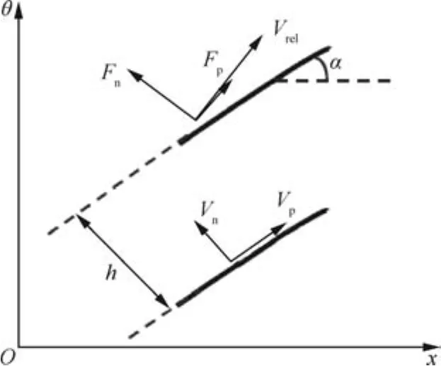
The body force model used in Eq.(8)for this study was based on the model developed by Gong8which makes the assumption of an infinite number of blades and axisymmetric flow in each infinitesimal blade passage.The cascade blade forces in the relative frame of reference are modeled as normal and tangential forces to the local flow as shown in Fig.1,which are similar to the lift and drag forces of an airfoil.In this figure,FnandVnare the force and velocity normal to the channel direction;FpandVpare the force and velocity parallel to the channel direction;his the blade-to-blade gap-staggered spacing;α the camber angle;Vrel=Vzcosθ-Vysinθ-rΩ is the relative tangential velocity component.

Fig.1 Illustration of body force components at blade-to-blade section.
2.2.1.Normal force model
In the present study,a modified formulation12was used to model the normal force:

whereKnis the normal force coefficient,cis the blade chord length and Δα is the camber angle difference between the trailing edge and leading edge.
Defoe13suggested an empirical model for determining the normal force coefficientKnfor a particular fan rotor:

whererhandrtare the hub and tip radius of the fan blade,respectively.The first expression in parentheses in Eq.(11),an empirically obtained term suggested in Ref.,8is multiplied by the bracketed expression to adjust the magnitude ofKnalong the spanwise direction.Kim and Liou12adopted a formulation forKnthat is very similar to Eq.(11):

wheref(r)is a set of line segments connecting control points with a spanwise distribution.Andg(˙mlocal)is an adjusting function,which depends on the local Mass Flow Rate(MFR)parameter.It can be expressed as

whereA(x)is the flow area at axial position ofx.
In this paper,the control points off(r)andg(˙mlocal)were adjusted to match available CFD or experimental data.The three components of the normal force are calculated by

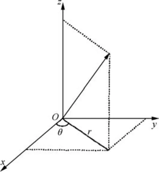
The relationship between cylindrical coordinates and Cartesian coordinates is shown in Fig.2.

Fig.2 Relationship between cylindrical coordinates and Cartesian coordinates.
2.2.2.Parallel force model
The component of the body forceFpfor the flow loss is obtained by Gong’s model.

whereKpis the parallel force coefficient and equals 0.04.The three components ofFpare calculated as follows:

3.Methodologies for flow simulation
3.1.Single-passage turbomachinery flow simulation
For single-passage Navier-Stokes flow simulations of the NASA Rotor 37,a commercial solver NUMECA Fine-Turbo EURANUS was used through a finite volume method.The NUMECA Fine-Turbo EURANUS is a threedimensional,multi-block,structured-grid Navier-Stokes analysis code for turbomachinery blade rows.The temporal discretization scheme is an explicit four-order Runge-Kutta scheme and the spatial discretization uses the second order accurate central-differenced scheme.The Spalart-Allmaras model is applied to close the turbulence terms.The choice is based on the earlier studies of turbomachines.14,15The computational domain only considers a single-blade passage with periodic boundary conditions imposed along the pitchwise direction.At the inlet,the total pressure and temperature are specified along with the flow angle.At the exit,which is placed at two chords downstream the trailing edge,the average static pressure is specified.The working fluid is considered to be a perfect gas.In addition,the no-slip and no-flux conditions are adopted on solid surfaces.The identical boundary conditions are used in all the calculations.
3.2.Coupled supersonic inlet-fan flow simulation
HMNF,a CFD module in COMSOL Multi-physics,was used for all the flow simulations in this study except turbomachinery single-passage simulations.The compressible Reynolds-averaged Navier-Stokes equations were discretized by the finite element method.And the solution domain was discretized into a series of small connected units,in which discrete linear algebraic equations were solved.The flux was computed using segregated solvers,which used a Newton’s method in each substep,and two-equation(k-e)model was used to incorporate turbulence effects.Parallel processing was accomplished by Cluster Computing,which could utilize shared-memory multicore processing on each code in combination with the Message Passing Interface(MPI)based distributed memory model.
In COMSOL Multi-physics,a number of different mesh types and meshing strategies for flow modeling were used,including unstructured meshes,structured meshes,swept meshes,and boundary layer meshes.For coupled axisymmetric supersonic inlet-fan calculations,swept meshes were typically ideal,which were a particular form of structured meshes for channels and pipes.These are generated in 3D structure by creating a mesh at a source face and then sweeping it along the domain to a destination face.Then,boundary layer meshes were used by inserting structured layers of elements near viscous walls.
4.Simulation results
4.1.Validation
4.1.1.Supersonic flow simulation
A 2D mixed compression inlet model16with a subsequent isolator section was used to validate the HMNF module for supersonic flows in COMSOL Multi-physics.The outline of the inlet contour and the definition of the main dimensions are given in Fig.3 and Table 1.
For Navier-Stokes flow simulations of the supersonic inlet,the HMNF module described earlier was used.At the inlet,the supersonic inflow was defined by specifying flow conditions.In case of predominant supersonic outflow,the variables were completely extrapolated from the interior onto the outflow boundary.At solid walls,the no-slip condition was enforced by setting the velocity components to zero.Fig.4 shows computational domain and grid detail for the supersonic inlet.
The normalized pressure distribution along with the surface is plotted in Fig.5,where the ordinate represents the static pressurepnormalized by the inlet total pressurepin,tot.It can be seen that HMNF results well agree with the experiment data.In Fig.5(a),because the computed separation appears smaller than that experimentally observed,the computed pressure is smaller than the measured result.But the error is tolerable for the supersonic inlet simulation.So,supersonic flow simulations performed withk-eturbulence model in the HMNF module of COMSOL Multi-physics could well simulate flow characteristics for the supersonic inlet.

Fig.3 Main dimensions of inlet model.

Table 1 Main dimensions of inlet model.

Fig.4 Computational domain and grid detail for supersonic inlet.

Fig.5 Surface pressure distribution along axial locations.

Table 2 Geometric and design parameters of NASA Rotor 37.

Fig.7 Rotor pressure ratio versus mass flow rate.
4.1.2.Viscous body force model
NASA Rotor 37,which was designed by NASA Glenn Research Center,was selected as the baseline compressor to validate the present viscous body force model.Table 2 summarizes the main geometric and design parameters of the rotor.For single-passage Navier-Stokes flow simulations of the Rotor 37,NUMECA Fine-Turbo EURANUS described earlier was used.And the HMNF module was run in compressible Reynolds-averaged Navier-Stokes equations with the body force source terms added.At the inlet,the total pressure and temperature were specified along with the flow angle.At the exit,which is placed at two chords downstream the trailing edge,the average static pressure was specified.The working fluid was considered to be a perfect gas.In addition,the noslip and no- flux conditions were adopted on solid surfaces.Fig.6 shows computational meshes for the Rotor 37,TE:trailing edge,LE:leading edge.
Fig.7 compares the rotor pressure ratio versus the mass flow rate at the design rotor speed.The experimental data,extracted from the Advisory Group for Aeronautical Research and Development(AGARD)Advisory Report 355 entitled ‘CFD Validation for Propulsion System Components”,agree very well with the results of the NUMECA Fine-Turbo EURANUS and the RANS simulation with the body force model.Fig.8 shows the total pressure contours normalized by the free-stream total pressure.The total pressure increases along the streamwise direction with an almost uniform slope.
In Fig.9,the spanwise distributions of pitch-averaged total pressure ratio,total temperature ratio and swirl angle at the rotor outlet for 98.7%choked mass flow are compared for NUMECA Fine-Turbo EURANUS and RANS+body force model.And the two results along the span are in good agreement.

Fig.8 Normalized total pressure contours at a meridional plane.

Fig.6 Computational mesh for Rotor 37.
4.2.Flow simulation of coupled supersonic inlet-fan
Flow simulations of a coupled supersonic inlet-fan configuration were conducted for a cruise flight condition:Mach number 2.8,an altitude of 98000 ft(1 ft=0.3048 m),and an angle of attack of 0°.A Fortran code was written,which uses shape and performance parameters to build the axisymmetric mixed compression supersonic inlet.And the connected fan, which has a 15 inch (1 inch=2.54 cm)diameter and 43 wide-chord blades,is the first stage rotor of a three-stage transonic axial-flow compressor shown in Fig.10.The performance specifications of the first stage rotor were that MFR is 4.49 kg/s,pressure ratio is 1.77,and rotor speed is 25,000 r/min.Some parameters for the coupled system are shown in Fig.11,and the explanations of these parameters are given in Table 3.A computational structured mesh was generated by COMSOL Multi-physics on the coupled configuration,as shown in Fig.12.And the local mesh refine approach near bleed slots was used to capture the flow field in detail.In Fig.13,numerical results for the fan(the first stage rotor)from the NUMECA Fine-Turbo EURANUS and the current Navier-Stokes simulation with the body force model were well matched by the body force model buildup.

Fig.10 Schematic diagram of transonic axial-flow compressor.

Fig.11 Side section view of schematic representation of coupled system parameterization.

Table 3 Explanation of parameters in Fig.11.
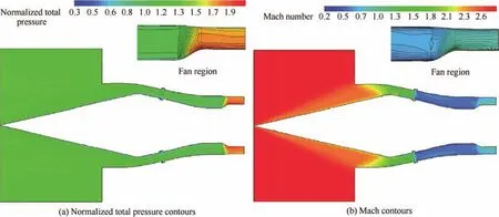
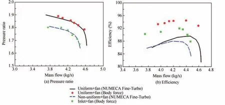
Fig.14 shows sectional side views of normalized total pressure contours and local Mach number for coupled supersonic inlet-fan simulations.The region that was swept by the fan blade and had the body force model applied could be easily recognized as the steep axial gradient of the total pressure contours.And from the Mach number contours,it can be seen that the terminal shock positioned itself within the stability bleed slot of the supersonic inlet17–19because of the high backpressure of the fan.Fig.15 compares the fan pressure ratio and efficiency versus mass flow rate for uniform inflow and coupled inlet-fan conditions.It is obvious that the fan pressure ratio for coupled inlet-fan simulations was lower than that for the uniform inflow condition.The interaction between oblique shock wave and boundary layers and the existence of bleed slots could cause the non-uniform distribution of the flow at the inlet-fan interface location.20In Fig.16,non-uniform aerodynamic parameters at the inlet-fan interface location(the vertical line in Fig.11)caused the difference between the uniform and non-uniform case,that the fan pressure ratio and stability margin were worse for the non-uniform case,as shown in Fig.15(a).However,because the total temperature at the compressor outlet was underestimated by the body force model,the efficiency was bigger for uniform inflow and coupled inlet-fan conditions.And in the case of uniform inflow,the efficiency was overestimated for two methods.

Fig.12 Computational mesh for coupled supersonic inlet-fan.

Fig.13 Generation of body force model for fan.

Fig.14 Center section contours.

Fig.15 Comparison for uniform and inlet-fan inflow conditions at design rotor speed.

Fig.16 Comparison of aerodynamic parameter distribution for uniform and inlet-fan inflow conditions.
5.Conclusions
In this paper,a coupled supersonic inlet-fan Navier–Stokes simulation method was developed using COMSOL-CFD code.The flow turning,pressure rise and loss effects across blade rows of the fan and the inlet-fan interactions were controlled by a body force model as source terms of the governing equations without a blade geometry.The following conclusions can be drawn:
(1)Based on the COMSOL-CFD code,the governing equations including viscous terms were written in nonconservative form in Cartesian coordinates with body forces as source terms on the right-hand side.Detailed viscous flow close to walls in blade passages was calculated directly.Computational results of the Rotor 37 indicate that this model could simulate flow field performance well.
(2)The COMSOL Multi-physics software environment was capable of facilitating all steps in the modeling and simulation processes from part defining,feature based meshing to visualization and solution analysis.Flow simulation results of the coupled supersonic inlet-fan demonstrate the validity of the present method.
(3)The inlet and fan were simulated simultaneously by different COMSOL modules,and the data transfer at each grid point of the inlet-fan interface was completed easily by the form of boundary conditions.In fact,aerodynamic parameters at the inlet-fan interface were nonuniform,which had a bad effect on the fan performance.
Acknowledgements
The authors acknowledge the support of National Natural Science Foundation of China(Nos.51706008 and 51636001),China Postdoctoral Science Foundation(No.2017M610742)and Aeronautics Power Foundation of China (No.6141B090315).
1.Kim H,Liou MS.Optimal shape design of mail-slot nacelle on N3-X hybrid wing-body con figuration.31st AIAA applied aerodynamics conference;2013 Jun 24–27;San Diego,USA.Reston:AIAA;2013.
2.Webster RS,Sreenivas K,Hyams DG,Hilbert B,Briley WR,Whit field DL.Demonstration of sub-system level simulations:A coupled inlet and turbofan stage.48th AIAA/ASME/SAE/ASEE joint propulsion conference&exhibit;2012 Jul 30-Aug 01;Atlanta,USA.Reston:AIAA;2012.
3.Rodriguez DL.Multidisciplinary optimization method for designing boundary-layer-ingesting inlets.J Aircraft2009;46(3):883–94.
4.Kim H,Kumano T,Liou MS,Povinelli LA,Conners TR.Flow simulation of supersonic inlet with bypass annular duct.J Propul Power2011;27(1):29–39.
5.O’Brien DM,Calvert ME,Butler SL.An examination of engine effects on helicopter aeromechanics.AHS specialist’s conference on aeromechanics.San Francisco,CA;2008 Jan 23–25.
6.Bush R.Engine face and screen loss model for CFD application.Reston:AIAA;1997.Report No.:AIAA-1997-2076.
7.Chima RV.Rapid calculations of three-dimensional inlet/fan interaction.NASA fundamental aeronautics 2007 annual meeting;2007 Oct 30-Nov 01;New Orleans,USA.Washington,D.C.:NASA;2007.
8.Gong Y.A computational model for rotating stall inception and inlet distortion in multistage compressors[dissertation].Cambridge:Massachusetts Institute of Technology;1999.
9.Hsiao E,Naimi M,Lewis JP,Dalbey K,Gong Y,Tan C.Actuator duct model of turbomachinery components for powered-nacelle Navier-Stokes calculations.J Propul Power2001;17(4):919–27.
10.Xu L.Assessing viscous body forces for unsteady calculations.J Turbomach2003;125(3):425–32.
11.ChimaRV.A three-dimensional unsteady CFD model of compressor stability.ASME turbo expo 2006:Power for land,sea,and air,volume 6:Turbomachinery,parts A and B;2006 May 08–11;Barcelona,Spain.New York:ASME;2006.p.1157–68.
12.Kim H,Liou MS.Flow simulation of N3-X hybrid wing-body con figuration.51th AIAA aerospace sciences meeting including the new horizons forum and aerospace exposition;2013 Jan 07-10;Grapevine,USA.Reston:AIAA;2013.
13.Defoe J.Inlet swirl distortion effects on the generation and propagation of fan rotor shock noise[dissertation].Cambridge:Massachusetts Institute of Technology;2011.
14.Lange M,Vogeler K,Mailach R,Gomez SE.An experimental verification of a new design for cantilevered stators with large hub clearances.J Turbomach2013;135(4):041022.
15.Wang YG,Chen WX,Wu CH,Ren SY.Effects of tip clearance size on the performance and tip leakage vortex in dual-rows counter-rotating compressor.Proc I MechE,Part G:J Aerospace Eng2014;229(11):1953–65.
16.Reinartz BU,Herrmann CD,Ballmann J,Koschel WW.Aerodynamic performance analysis of a hypersonic inlet isolator using computation and experiment.J Propul Power2003;19(5):868–75.
17.Domel N,Baruzzini D,Miller D.A perspective on mixed compression inlets and the use of CFD and flow control in the design process.50th AIAA aerospace sciences meeting including the new horizons forum and aerospace exposition;2012 Jan 09–12;Nashville,USA.Reston:AIAA;2012.
18.Li QS,Lv YZ,Li SB.A quasi one-dimensional bleed flow rate model for terminal normal shock stability in mixed compression supersonic inlet.Proc IMechE,Part C:J Mech Eng Sci2014;228(14):2569–83.
19.Lv YZ,Li QS,Li SB.Modeling the effect of stability bleed on back-pressure in mixed-compression supersonic inlets.ASME J Fluids Eng2015;137(12):121101.
20.Voytovych DM,Merkle CL.Simulation of coupled supersonic inlet and a fan.46th AIAA/ASME/SAE/ASEE joint propulsion conference&exhibit;2010 Jul 25–28;Nashville,USA.Reston:AIAA;2010.
杂志排行
CHINESE JOURNAL OF AERONAUTICS的其它文章
- A self-similar solution of a curved shock wave and its time-dependent force variation for a starting flat plate airfoil in supersonic flow
- Robust Navier-Stokes method for predicting unsteady flowfield and aerodynamic characteristics of helicopter rotor
- Effects of trips on the oscillatory flow of an axisymmetric hypersonic inlet with downstream throttle
- An equilibrium multi-objective optimum design for non-circular clearance hole of disk with discrete variables
- Shock/shock interactions between bodies and wings
- Modeling and control for cooperative transport of a slung fluid container using quadrotors
