Shock/shock interactions between bodies and wings
2018-03-21GaoxiangXIANGChunWANGHonghuiTENGZonglinJIANG
Gaoxiang XIANG,Chun WANG,Honghui TENG,Zonglin JIANG
aSchool of Mechanics,Civil Engineering&Architecture,Northwestern Polytechnical University,Xi’an 710129,China
bInstitute of Mechanics,Chinese Academy of Sciences,Beijing 100190,China
1.Introduction
In aerospace engineering,the prediction of aerodynamic heating is very important for the design of supersonic or hypersonic aircraft.There are two approaches to estimate aerodynamic heating in protective engineering.The first method is to use correlations between pressure and heating to predict the aerodynamic heating,which assumes that the aerodynamic heating is positively related to the pressure or density.1This approach is applied to the simple geometric shapes well;however,it could not predict the aerodynamic heating well for the complex geometric shape.The second method considers the location of Shock/Shock Interaction(SSI)or the interactive wave configuration as the key factors of aerodynamic heating2,but the mechanism has not been well established.Thus,the problem of SSI is very important to the prediction of aerodynamic heating.
Regarding the SSI induced by the body and wing of aircraft,many researchers have conducted numerous experimental and numerical studies.3–7Zheltovodov and Schulein3–5conducted experimental and theoretical(computational)investigations on a model of one fin mounted on a flat plate at Mach number 3,and the technology of surface oil flow and flow visualization by Planar Laser Scattering(PLS)was used in his experiments.He also considered the effects of the de flec-tion angle of the fin on surface pressure and wave configuration.Horstman and Hung6used the Reynolds-Averaged Navier–Stokes(RANS)simulation with a simple algebraic eddy-viscosity turbulence model to compute streamline trajectory.Schulein7performed experiments to study the surface pressure and skin-friction distributions at Mach number 5.Other researchers also study the SSI by using different models.8–15In the above research,the plate was flat and only the Shock wave-Boundary-Layer Interactions(SBLIs)were taken into consideration.In the design of hypersonic aircraft,the high heat flux may be caused by SSI and SBLIs.Therefore,the interactions between incident waves induced by the plate and the fin are very important for the prediction of heat flux in these regions.
Compared to the experimental and numerical researches,the theoretical research is seldom conducted.The earliest theories about 2D Regular Reflection(RR)and Mach Reflection(MR)were proposed by von Neumann,16,17who termed them as the two-shock theory and three-shock theory.Based on these theories,Kawamura and Saito18developed the(p,θ)-polar method,wherepdenotes the flow static pressure and θ is the flow deflection angles,to describe the shock reflection and SSI problems.Ben-Dor19used the(p,θ)-polar method to analyze various shock reflection and interaction wave configurations.However,the above theories are 2D,and in fact,there is no theory for the 3D cases.Recently,Yang and Xiang et al.developed a spatial dimension reduction approach to analyze the 3D SSI.20–24Through the use of the new theoretical method,the 3D steady SSI problem can be treated as a 2D unsteady one,and then,the flow structures could be solved by shock dynamic.
In this paper,the SSIs induced by bodies and wings were studied numerically and theoretically.The spatial dimension reduction method is used to analyze the flow parameter and the results are compared with the numerical results.In Section 2,the procedures and numerical methods are simply presented.Numerical results and theoretical analysis are given and discussed in detail in Section 3.Finally,the conclusions are drawn in Section 4.
2.Analytical approach and numerical methods
As depicted in Fig.1,the numerical model is a simplified symmetrical model of a wing and body,where the body is replaced by a wedge and the wing is assumed to be a sharp wing.The wedge angle of the body is θ,and the body isLin length,din width andhin height.The distance from the front point of the wingOto the leading edge of the body isl1,Ais the top point of the wing.λ2is the sweep angle of the wing,and is formed by the leading edge of the wing and the horizontal line.Half angle of the wedge is defined as θ1,and the height of the wing ish1.
For the free inviscid inflowMa0,the incident waveCBFis induced by the body,the incident waveAPRis induced by the wing,and they interact with each other in the corner as shown in Fig.2.Two reflected waves,OPRandPRG,occur due to the intersection of the two incident waves.The computational zone is selected as half of the model,which is divided by the symmetry plane.The intersecting line of the two incident waves,PR,is defined as the characteristic direction,and the planeNMDperpendicular to it is defined as the characteristic plane.Qis the intersecting point of linePRand the planeNMD.In the interactive zone,the wave configuration is selfsimilar in the direction of the characteristic line,and thus,the 3D steady SSI could be regarded as a 2D SSI in the characteristic plane moving in the direction of the characteristic linePR.
The decomposed Mach number projected onPRisMan.The decomposed Mach numbersMas1andMas2on the characteristic plane are given by
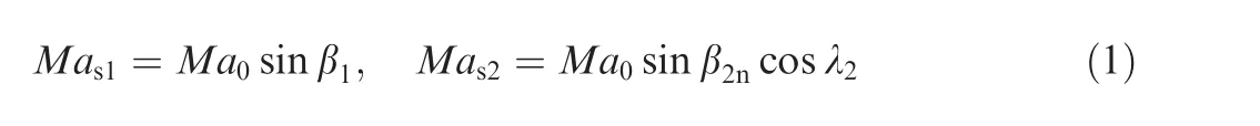
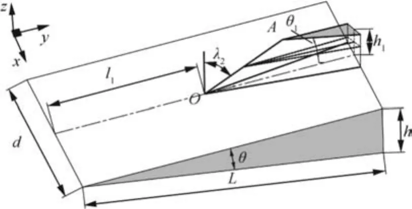
Fig.1 Schematic illustration of a simplified model for wing and body.
where β1is the shock angle in the direction of the incoming flow,and β2nis the shock angle perpendicular to the leading edge of the wing.
When the above geometrical relationships between 3D steady problem and 2D unsteady problem are determined,the problem of 3D could be regarded as the interaction of two incident wavesMas1andMas2moving on the characteristic plane,which can be treated as the characteristic plane moving in the direction of the characteristic linePR.
The determination of the wave configurations could be achieved by shock polar analysis of the2D unsteady problem.18,19
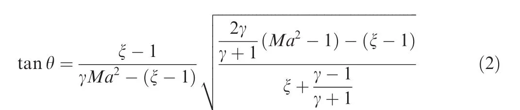
whereMais the decomposed Mach number in the direction of the reflection point,γ is 1.4 for an ideal gas,and ξ is the ratio of the pressure behind the waves.

Fig.2 Schematic of ‘spatial-dimension reduction” approach.
If the wave configuration is Mach interaction,a Mach stem is formed betweenMas1andMas2.The Mach number behind the Mach stemMamand the location of the Mach stem can be given by the shock dynamics.25,26
Here,f(Ma)is a function in terms of the Mach numberMa.θvis the angle between the virtual wall and the horizontal line.η is the angle between two incident waves.Then,all the parameters in the 2D flow field could be obtained.For the 3D flow field,the state parameters,such as the temperature,pressure,density and the total pressure recovery coefficient,are identical to those of the 2D unsteady solutions.The vector parameters,such as the velocities and Mach number,should be composed with the decomposed vectors in the direction of the characteristic line.
For the numerical computations,the 3D inviscid Euler equations of a perfect compressible gas were solved.The code was developed at the Shock Wave and Detonation Physics Laboratory and run on a DELL 8-core computer.It used a Non-oscillatory and Non-free-parameters Dissipative finite difference(NND)scheme,27which was based on an orthogonalized uniform structured mesh,with a mesh number of 120×200×200 in thex,yandzdirections.The Message Passing Interface(MPI)parallel program was used in the code.Mesh independent tests were performed to ensure that all the results produced were independent of the type of mesh chosen for the numerical simulations.
3.Presentation of results
In this section,theoretical and numerical researches are conducted to explore the impacts of geometric parameters on the flow field and wave configuration.Due to the symmetry of the model,only half of the general numerical simulations are carried out.The coming flow Mach number is selected as 7.03,and the geometric parameters of wing and body for the numerical computations are listed in Table 1.In order to study the effects of the thickness of the wing,Cases 1 to 3 are conducted at wedge angle θ1of 2°,5°and 10°,where the other parameters are fixed at λ2=30°,L=1200 mm,d=500 mm,h1=350 mm,l1=500.9 mm,θ =3.5°.In Cases 1,4 and 5,the sweep angle varies from 30°to 60°,and other parameters are fixed.
For the Cases 1 to 5,the incident wave induced by the body intersects with the incident wave induced by the wing,and several of the wave configurations are formed.When the height of the wingh1is sufficiently small(see Case 6 and Fig.3),the incident wave induced by the body does not intersect the incident wave induced by the wing,and the high heat flux induced by the SSI on the side of the wing does not occur.In this situation,the expansion waves induced by the wall of the wing form in order to match the two incident waves and make the incident waves induced by the wing curved.
3.1.Effects of wedge angle of wing
The wedge angle of the wing corresponds to the thickness of the wing(Fig.1),which is a key parameter for designing the aircraft.For Cases 1 to 3,shock polar analysis on the crosssection indicates that the two reflected polar do not intersect each other and it means that a Mach interaction will occur in the side of the wing(Fig.4(a)).As depicted in Fig.4(a),when the wedge angle of the wing increases,two incident polarIi,andIi′,and the reflected polarRinear the body grow bigger and higher,while the reflected polarR’inear the wing becomes smaller and changes into a point at θ1=10°,which implies that the flow behind the incident wave on the characteristic plane is subsonic and the(p,θ)polar does not exist.When the reflected polar is totally on the incident polar or recessed into one point,it means that the reflection is a weak reflection and the reflected wave degenerates into an expansion wave on this side(Fig.4(d)).
The salient feature of hypersonic interactions is the occurrence of high heat transfer rates in the interaction region,which consists of the domain of SBLIs and SSI.In this paper,the viscosity is negligible,while the location of the SBLIs induced by the reflected wave and the boundary layer can be predicted using the inviscid results(Fig.4(b)–(d)).The intersecting point of the wall boundary and the reflected wave gets farther in the positive direction of thexandzaxes as θ1increases(Figs.4(b)–(d),5,8 and 4,7).It should be noted that the reflected wave near the wing changed into an expansion wave at θ1=10°,and the intersecting point almost reaches the top of the wing,where the thermal protection should be considered.Compared to the wing,the location of the reflected wave on the wall boundary on the side of the body changedslowly in the positive direction of the axis.Another region of high heat flux is caused by the SSI behind the Mach stem 3.This zone grows larger with the increase of θ1due to the increasing length of the Mach stem.The high heat flux region forms by the slip line 6 and the Mach stem gets larger with the increase of θ1.The temperature and pressure behind the Mach stem can be solved by the spatial dimension reduction approach.
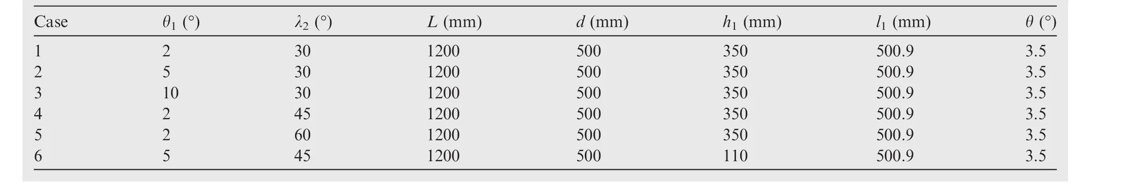
Table 1 Geometric parameters of wing and body in numerical computations.
As shown in Fig.5(a)and(b),the abscissa axis is the varying wedge angle of the wing θ1,and the vertical axis is the parameter ratio behind the Mach stem(Tb,Pb)and in front of the Mach stem(Tf,Pf).As illustrated in Fig.5,the theoretical solutions in the vicinity of the Mach stem are in good agreement with the numerical results.The temperature ratio and pressure ratio gradually increase with the increasing thickness of the wing.The temperature behind the Mach stemTbis about twice that of the inflow,and the pressure is about five times that of the inflow.Accordingly,the SSI in the distance should not be ignored in the design of aircraft.

Fig.3 Numerical result for case 6.
3.2.Effects of sweep angle of wing

Fig.4 Analytical and numerical results for varying wedge angle of wing at y=1200 mm(Note:1— incident wave of body;2—incident wave of wing;3—Mach stem;4—reflected wave near body;5—reflected wave near wing;6—slip line;7—wall boundary of body;8—wall boundary of wing;9—expansion fan near wing).
The impacts of the sweep angle λ2are investigated here using examples of Cases 1,4 and 5.The evolution of the shock-polar analysis on the cross-sections at λ2=30°,45°and 60°is shown in Fig.6.As λ2increases,the incident polar and the reflected polar get smaller and lower,where the two reflected polar do not interact with each other,indicating that the wave configurations are Mach interactions.The corresponding cross-sectional flow structures are shown in Figs.4(b)and 7(a)and(b).
Compared with θ1,the effects of λ2on the wave configurations are negligible.The increase of the sweep angle does not cause any obvious change on the location of the reflected waves and the Mach stem.This means that the region of high heat flux induced by the SSI and SBLIs changes very slowly with the varying sweep angle λ2.However,for the high heat transfer rate behind the Mach stem,the sweep angle exhibits the opposite tendency,where the increase of λ2leads to a reduction of the pressure and temperature behind the Mach stem(see Fig.8(a)and(b)).The results shown in Figs.5 and 8 reveal that the impacts of the sweep angle on pressure and temperature are smaller than those of the wedge angle.
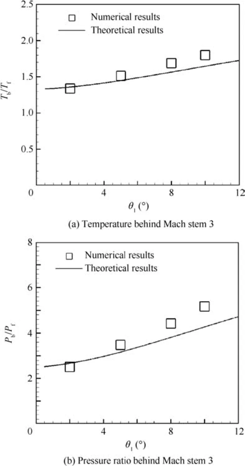
Fig.5 Analytical and numerical results after varying wedge angle of wing.
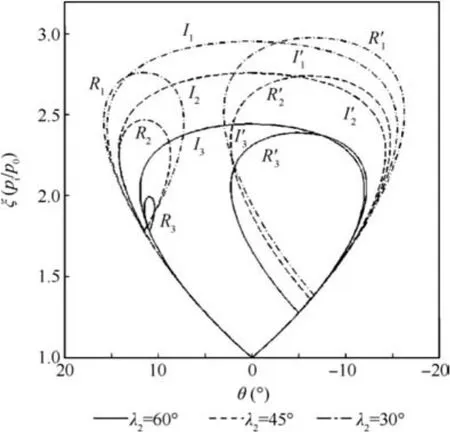
Fig.6 Shock polar analysis after varying sweep angle of wing at y=1200 mm.
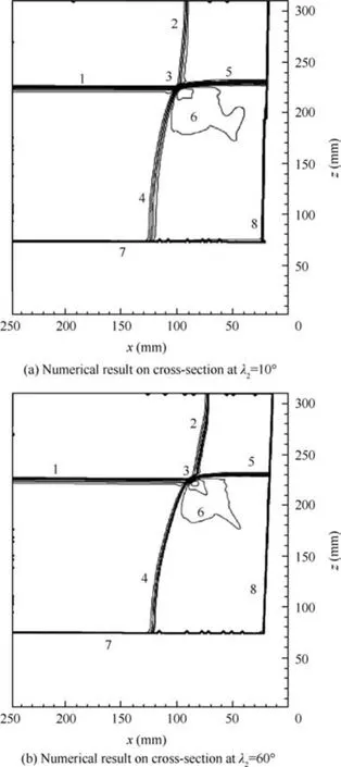
Fig.7 Numerical results after varying sweep angle of wing at y=1200 mm.

Fig.8 Analytical and numerical results after varying sweep angle of wing.
4.Conclusions
(1)In this study,the method of spatial dimension reduction is applied to study the SSI induced by the bodies and the wings.The wave configuration can be determined by shock polar analysis on the cross-section,and the flow field parameters in the vicinity of the Mach stem can be predicted by this method,which are in good agreement with the numerical results.The location of the high heat flux caused by the interaction with the reflected wave and the boundary layer can be predicted by the inviscid results.
(2)If the incident wave of the body interacts with the incident wave of the wing,several wave configurations occur in the interactive region.However,if the height of the wing is sufficiently small or the wedge angle of the body is larger,the two incident waves do not interact with each other and an expansion fan is formed at the top of the wall of the wing.
(3)As the wedge angle of the wing increases,the pressure and high heat flux behind the Mach stem induced by the SSI clearly rise up obviously,while the area that is formed by the Mach stem and slip lines gets bigger due to the increasing length of the Mach stem.The flow field parameters behind the Mach stem exhibit the opposite trend with the increase of the sweep angle of the wing,and the impacts can be considered negligible compared with the wedge angle.
(4)For the sufficiently large wedge angle of the wing,the wave configuration is a weak reflection.The reflected wave near the wall of the wing changes into an expansion fan according to the theoretical and numerical analyses,and the impacts can be considered negligible compared with the wedge angle.The intersecting point of the wall boundary and the reflected waves get farther in the positive direction ofxandzaxes as the wedge angle of the wing increases.However,this intersecting point changes little with the increase of the sweep angle.
Acknowledgements
The authors would like to thank Prof.LUO CT and HU ZM for their valuable assistance.This paper is supported by the Fundamental Research Funds for the Central Universities of China(No.31020170QD087).
1.Neumann RD,Burke GL.The influence of shock wave-boundary layer effects on the design of hypersonic aircraft.Wright-Patterson AFB:Air Force Flight Dynamics Lab;1969.Report No.:AFFDL-TR-68-152.
2.Edney B.Anomalous heat transfer and pressure distributions on blunt bodies at hypersonic speeds in the presence of an impinging shock.Stockholm:The Aeronautical Research Institute of Sweden;1968.Report No.:FFA-115.
3.Zheltovodov AA.Some advances in research of shock wave turbulent boundary-layer interactions.Reston:AIAA;2006.Report No.:AIAA-2006-0496.
4.Zheltovodov AA.Shock waves/turbulent boundary-layer interactions—Fundamental studies and applications.Reston:AIAA;1996.Report No.:AIAA-1996-1977.
5.Zheltovodov AA,Schulein E.Three-dimensional swept shock waves/turbulent boundary layer interaction in angle con figurations.Novosibirsk:USSR Academy of Sciences;1986[Russian].
6.Horstman CC,Hung CM.Computation of three-dimensional turbulent separated flows at supersonic speeds.AIAA J1979;17(11):1155–6.
7.Schulein E.Skin friction and heat flux measurements in shock/boundary layer interaction flows.AIAA J2006;44(8):1732–41.
8.Wang C,Xiang GX,Jiang ZL.Theoretical approach to one dimensional detonation instability.Appl Math Mech2016;37(9):1231–8.
9.Hu ZM,Wang C,Zhang Y,Myong RS.Computational confirmation of an abnormal Mach reflection wave con figuration.Phys Fluids2009;21(1):011702.
10.Zhai ZG,Wang MH,Si T,Luo XS.On the interaction of a planar shock with a light polygonal interface.JFluidMech2014;757:800–16.
11.Zhai ZG,Si T,Luo XS,Yang JM.On the evolution of spherical gas interfaces accelerated by a planar shock wave.Phys Fluids2011;23:84–104.
12.Zhai ZG,Liu CL,Qin FH,Yang JM,Luo XS.Generation of cylindrical converging shock waves based on shock dynamics theory.Phys Fluids2010;22:041701.
13.Xue XP,Nishiyama Y,Nakamura Y,Mori K,Wang YP,Wen CY.High-speed unsteady flows past two-body con figurations.Chinese Journal of Aeronautics2018;31(1):54–64.
14.Wang HY,Li J,Jin D,Dai H,Gan T,Wu Y.Effect of a transverse plasma jet on a shock wave induced by a ramp.Chin J Aeronaut2017;30(6):1854–65.
15.Chen ZJ,Lin J,Bai CY,Wu ZN.A self-similar solution ofa curved shock wave and its time-dependent force variation for a starting flat plate airfoil in supersonic flow.Chin J Aeronaut2018;31(2):205–13.
16.von Neumann J.Refraction,interaction and reflection of shock waves.Washington,D.C.:U.S.Navy,Bureau of Ordnance;1943.Report No.:203-45.
17.von Neumann J.Oblique reflection of shock waves.Oxford:Pergamon Press;1996.
18.Kawamura R,Saito H.Reflection of shock waves—1 Pseudostationary case.J Phys Soc Jpn1956;11(5):584–92.
19.Ben-Dor G.Shockwavereflectionphenomena. 2nd ed.Berlin:Springer-Verlag;2007.p.134–93.
20.Yang Y,Wang C,Jiang ZL.Analytical and numerical investigations of the reflection of asymmetric nonstationary shock waves.Shock Waves2012;22(54):435–49.
21.Xiang GX,Wang C,Teng HH,Jiang ZL.Study on Mach stems induced by interaction of planar shock waves on two intersecting wedges.Acta Mech Sinica2016;32(3):362–8.
22.Xiang GX,Wang C,Teng HH,Jiang ZL.Investigations of threedimensional shock/shock interactions over symmetrical intersecting wedges.AIAA J2016;54(5):1–10.
23.Xiang GX,Wang C,Hu ZM,Jiang ZL.Theoretical solutions to three-dimensional asymmetrical shock/shock interaction.Sci China Technol Sci2016;59(8):1208–16.
24.Xiang G,Wang C,Teng H.Three-dimensional shock wave con figurations induced by two asymmetrical intersecting wedges in supersonic flow.Shock Waves2017;1:1–9.
25.Yang Y.Analytical and numerical investigations of the reflection of asymmetric nonstationary shock waves.Shock Waves2012;22(5):435–49.
26.Xie P.A study of the interaction between two triple points.Shock Waves2005;14(1):29–36.
27.Zhang HX.A dissipative difference scheme of non-oscillatory,no-free parameters.Acta Aerodynamica Sinica1988;6(2):143–65[in Chinese].
杂志排行

CHINESE JOURNAL OF AERONAUTICS的其它文章
- A self-similar solution of a curved shock wave and its time-dependent force variation for a starting flat plate airfoil in supersonic flow
- Robust Navier-Stokes method for predicting unsteady flowfield and aerodynamic characteristics of helicopter rotor
- Effects of trips on the oscillatory flow of an axisymmetric hypersonic inlet with downstream throttle
- Development of a coupled supersonic inlet-fan Navier–Stokes simulation method
- An equilibrium multi-objective optimum design for non-circular clearance hole of disk with discrete variables
- Modeling and control for cooperative transport of a slung fluid container using quadrotors