Impact of the thermal effect on the load-carrying capacity of a slipper pair for an aviation axial-piston pump
2018-03-21HeshengTANGYooYINYnRENJiweiXIANGJunCHEN
Hesheng TANG,Yoo YIN,Yn REN,Jiwei XIANG,Jun CHEN
aSchool of Mechanical Engineering,WenZhou University,Wenzhou 325035,China
bSchool of Mechanical Engineering,Tongji University,Shanghai 201804,China
cSany Heavy Industry Co.,Ltd,Changsha 410100,China
1.Introduction
An aviation axial-piston pump is widely used in an aircraft hydraulic system for supplying hydraulic power to a flight actuator because it has high output pressure,high efficiency,and high reliability.For the development of an axial piston pump with a higher efficiency rate and a simultaneously high service life,an optimal gap design allowing a minimum of friction and volumetric losses in the given parameter range of a machine is urgently necessary.A large number of studies have been concerned about optimization gap design,1vibration and noise reductions,2,3and variable control about axial piston pumps.4A slipper pair is one of the key friction pairs,which provides extremely low friction and high positional accuracy,and is often preferred in an aviation axial-piston pump.
In a slipper pair,a fluid film separating the contacting surfaces is maintained by external pressure.The separating film has a high load-carrying capacity and,therefore,does not break down even at extremely low speed during starting,stopping,or changing the direction of rotation.However,an aviation axial-piston pump generates strengthened interactions among thermal,fluid,and structures in the conversion process from mechanical energy to hydraulic energy at high-pressure and high-rotational speed conditions.The strengthened thermal-fluid-structure coupling effect makes the oil viscosity drastically change,the load-carrying capacity drop,lubrication failure,and wear in the slipper pair.Therefore,it is an urgent need to study the load-carrying capacity of the slipper pair.
In the past 40 years,the lubrication performance of a slipper pair in an axial piston pump has been studied from theoretical and experimental aspects. Koc and Hooke5experimentally studied the effects of the clamping ratio and orifice size on the performance of slippers.The results showed that the slippers ran satisfactorily with no orifice and had their greatest resistances to tilting couples and minimum film thickness.Kazama and Yamaguchi6experimentally examined mixed lubrication characteristics of hydrostatic thrust bearings.They measured the frictional force and leakage flow rate under a lubrication range from mixed to fluid film based on an apparatus featuring circular hydrostatic thrust bearings acting on concentric loads.Harris et al.7developed a dynamic model to investigate the dynamic behavior of slipper pads.This model was incorporated into the Computer Aided Pump Performance Analysis(CAPPA)suite of models for use as a part of the simulation package Bathfp,and was used to examine the dynamic stability of slipper pads.It was found that the slipper of an axial piston pump ran heavily tilted for high speeds,and touched both the swash-plate and the retaining plate during a pumping cycle.Borghi et al.8investigated the dynamic behavior of a slipper bearing of an axial piston machine.A numerical procedure was used to solve the Reynolds equation with respect to the slipper-swash plate gap.Lu et al.9studied the fluid lubrication characteristics and the anti-turnover ability of a three-cavity independent slipper based on a computational fluid dynamics(CFD)model,taking into account the inertia and the surface roughness.Murrenhoff and Scharf10studied the influences of the gaps geometry and their tribological characteristics on the total efficiency based on a test rig.Deeken11developed a computer tool DSHplus to evaluate the dynamic behavior of an axial piston machine.The hydraulic characteristics and frictions between the key tribo-pairs were analyzed.Canbulut et al.12used artificial neural networks to analyze the performance of slipper bearings,which included experimental results and a consideration of the elastohydrostatic problem.Manring et al.13experimentally investigated the performance of slippers using different assumed socket geometries at low speed.The results showed that the leakage and capacity were affected by elastic deformation.Nie et al.14analyzed the influences of structural parameters and running conditions on the wear behavior for a swash plate/slipper pair of a water pump,and drew conclusions by conducting testing.An analytical solution for the hydrostatic leakage and lift characteristic of slippers with multiple lands was outlined by Bergada and Watton,15and another work by Bergada et al.16considered tilt but with no tangential speed effect.Kumar et al.17described the static and dynamic characteristics of a piston pump slipper with groove.Three-dimensional Navier-Stokes equations in cylindrical coordinates were applied to the grooved slipper/swash plate gap.Ma et al.18presented a method on the basis of an elasto hydrodynamic lubrication(EHL)model to analyze the wear behavior of a swash plate/slipper pair.Based on the analysis of film thickness,the associated internal factors affecting the wear behavior were identified by considering comprehensively structural parameters,working conditions,and material properties.Chen et al.19developed a computational fluid dynamics(CFD)simulation method based on a 3-D Navier-Stokes equation and the arbitrary Lagrangian-Eulerian(ALE)method to analyze the grooved slipper performance of a piston pump.Farid Ayada et al.20performed a parametric study to investigate the effect of the side clearance width on the pump impeller efficiency and head.The pump performance was highlighted through monitoring the changes of the pump head and efficiency.Lin and Hu21proposed a tribo-dynamic model of slipper bearings in axial piston pumps.The tribo-dynamic model was produced that considered the fluid–solid coupling to accurately describe the behavior of slippers.The behavior of the slippers was affected by factors such as the pressure field,the slipper pro file,the non-uniform gap between the slipper and the swash plate,external forces and motions,and elastic deformation.
In recent years,Kazama22investigated the effects of oil physical properties on the thermo-hydrodynamic performance of hybrid thrust bearings and considered various operation conditions.In 2014,the thermo-elasto-hydrodynamic(TEHD)performance of a slipper pair under high pressure and high rotation speed condition was validated using an experimental setup.23Meanwhile,the TEHD performance of the slipper pair was studied by solving the Reynolds equation and energy equation using numerical methods.These methods suffered significant limitations,such as wavelet finite element24or B-spline wavelet finite element,25when advanced fluid-structure coupling and thermal analysis of the slipper pair were discussed.Ivantysynova and Huang26analyzed the elastohydrodynamic effect in the gap flow model of a slipper pair.In 2015,a transient TEHD lubrication model for a slipper in an axial piston machine was developed,in which a nonisothermal fluid model,the micro dynamic motion of the slipper,as well as pressure and thermal deformation were considered,27and the temperatures at the port and case of the pump were predicted.28Hashemi et al.29developed a thermal elastohydrodynamics and mixed lubrication model for the sliding interface between a slipper and a swash plate in an axial piston pump.A model for calculation of multibody dynamics incorporating a transient,three-dimensional,thermal elastohydrodynamic pivot pad contact in swash plate axial piston pumps was presented.Xu et al.30established a numerical model of the lubrication between a slipper and a swash plate based on kinematic analysis and laminar flow assumption.This model can calculate the dynamic micro-motion,pressure distribution,and leakage of a slipper/swash-plate friction pair,which helps to reveal the principles for carrying ability and partial abrasion.In 2015,31they used the numerical model of the lubricating oil film to study the effect of the case drain pressure on the lubricating oil film.Tang et al.32developed a set of lumped parameter mathematical models based on the energy conservation law of a slipper/swash plate pair.The influence of the thermal effect on the load-carrying capacity of an axial piston pump was investigated.Based on the mathematical model,a parametric study was conducted on the lubrication characteristics of the slipper bearing considering the thermal effect of oil viscosity.33
By analyzing the above-mentioned literature,the following problems exist in a slipper pair of an aviation axial-piston pump.(1)In high-pressure and high-speed conditions,there has not been a mathematical model to accurately predict the film thickness and load-carrying capacity of the slipper pair at present because the thermo-hydrodynamic problem of the slipper pair is difficult to be considered.(2)Shear flow induced by the high-speed rotation and pressure difference flow induced by high-pressure difference in the slipper pair make the transient flow and viscous heating problems more obvious.(3)The heat transfer problem is more complex between the friction pair and the fluid film.(4)The influence of thermal on lubricant oil properties has not been paid much attention.
This paper presents a thermal hydraulic model to analyze the load-carrying capacity of a slipper pair in an aviation axial-piston pump.The slipper pair is taken as the research object in the paper.Section 2 is the problem formulation.A thermal hydraulic model is established based on a lumped parameter approach in Section 3.A numerical calculation is carried out by the matlab program.In Section 4,the effects of operating conditions on film thickness and load-carrying capacity are discussed,such as oil temperature,load pressure,and shaft rotational speed.The structural parameters of the slipper can be optimized to achieve desired performance,such as the slipper radius ratio and the orifice length diameter ratio.
2.Problem formulation
The schematic diagram of a typical axial-piston pump is shown in Fig.1.The main components of the pump are a drive shaft,a swash plate,a cylinder block with reciprocating pistons,and a valve plate.The valve plate separates a discharge port and a suction port.When the cylinder block and the shaft rotate clockwise,a piston moves within the cylinder toward the valve plate and discharges the fluid in the piston chamber to the discharge port.Then the piston begins to move toward the swash plate,and the fluid rushes into the piston chamber through the suction port.The discharge and suction processes define one completed pumping cycle for one piston.Of course,other than the main flow through the piston chambers,certain leakage flow takes place in the pump.As shown in Fig.1,the leakage flow is through the clearance between the slipper and the swash plate.The leakage flow depends on the pressure difference between a piston chamber and the respective flow path resistances.
At high-temperature and high-rotational speed conditions,power loss of the slipper pair due to high-pressure difference leakage and high-speed shear flow is converted into thermal energy,resulting in an oil temperature increase and an oil viscosity decrease.The thermal effect is enhanced in the slipper pair,which affects the lubricating gap film performance and load-carrying capacity.These usually cause a ripple of fluid temperature and pressure,which leads to an unsteady operation of the axial piston pump and adhesive wear of the slipper and the swash plate occurring on the local contact surface,and determine the service life of the pump.Therefore,a prediction of the load-carrying capacity of the slipper pair has great significance,which is beneficial to improve the reliability of the axial piston pump.
3.Establishment of a mathematical model
3.1.Mechanical model
The external forces applied on the slipper pair are shown in Fig.2.The inertial force of the piston bore caused by nonconstant flow is not considered.The hydraulic clamping force is caused by the piston structure.The axial hydraulic dynamics force in the oil film for the slipper pair is mainly affected by the external forces,including the hydraulic force,the return spring force,the axial inertial force,the friction force caused by the centrifugal force,and the cylinder bore friction reaction forces.With the coordinate system in Fig.2,the force balance equation on thez-axis of the slipper pair is listed as


Fig.1 Main components of an aviation axial-piston pump.
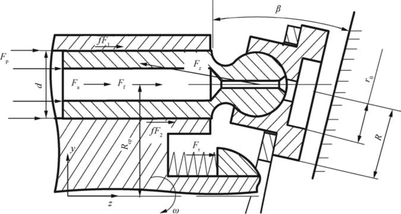
Fig.2 External forces applied on the slipper.
whereFzis thez-axial force,Fpis the hydraulic force,Fris the return spring force,Ffis the friction force caused by the centrifugal force,Fais the axial inertial force,β is the swash plate angle,F1andF2are the acting forces of a piston,andfis the friction coefficient.
The hydraulic force and return spring force can be presented respectively as

wheredis the piston diameter,xis the spring displacement,kis the spring stiffness,φ is the shaft angle,Rcpis the pitch radius,andppis the load pressure.
As shown in Fig.2,when the angle velocity of the shaft(ω)is set at a certain value,the axial inertial force and friction force are proportional to the angle velocity of the shaft.The axial inertial force and friction force can be presented respectively as
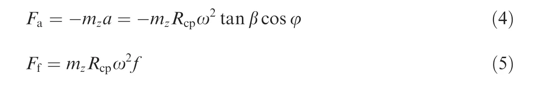
wheremzis the slipper mass,ω is the angle velocity,andais the acceleration.
Therefore,the axial force acting on the slipper can be obtained as

3.2.Film thickness model
In Fig.2,the slipper is mainly held against the swash plate by the completely axial forcesFz,including the piston pressure force,the piston friction force,and the inertia force.Therefore,the external forces mentioned above are in equilibrium with the bearing forces generated by the lubrication oil film between the slipper and the swash plate.In addition,the bearing forces from the fluid film include the hydrostatic bearing force,the thermal wedge bearing force,and the squeezing force.
According to Fig.2,the following equation can calculate the axial force:

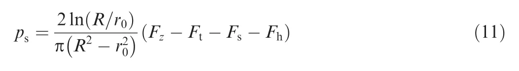
whereRis the slipper outside radius,r0is the slipper inside radius,andpsis the slipper pocket pressure.
The thermal wedge bearing force is written as34

where αpis the pressure coefficient, μ is the oil viscosity,Gis the equivalent power,ωsis the angular velocity of the slipper,ρ is the oil density,cpis the fluid specific heat,gis the acceleration of gravity,δ is the film thickness,andtis the simulation time.
The squeezing force equation at the sealing land of the slipper can be described as34
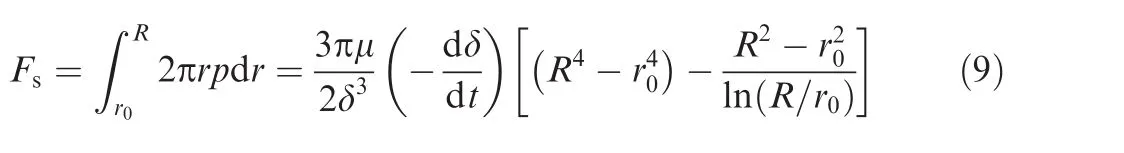

Fig.3 Schematic diagram of the slipper pair.
whereFsis the squeezing force,pis the film pressure,andris the slipper radius.
According to the schematic diagram of the slipper pair shown in Fig.3,the hydrodynamic bearing force is written as34

whereFhis the hydrodynamic bearing force,vis the slipper velocity,Lis the width of the slipper sealing land,andl1is the depth of groove.
Thus,substituting Eqs.(6)–(10)into Eq.(11),the slipper pocket pressure can be expressed as
Because the load-carrying capacity of the oil film in the slipper pair depends on the slipper pocket pressure,to keep a force balance between the load-carrying force and the slipper pocket pressure,an orifice is installed at the inlet of the slipper.Thus,the leakage flow rate of the orifice is written as
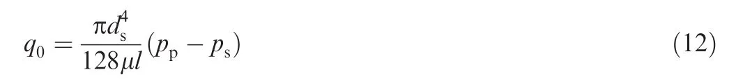
whereq0is the leakage flow rate,lis the orifice length,anddsis the orifice diameter.
Meanwhile,the pressure flow characteristic of the orifice is considered as a case of gap flow in a parallel disk.Thus,the flow rate of fluid film flowing via the clearance between the slipper and the swash plate can be written as

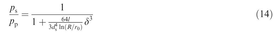
According to the principle of fluid continuity,substituting Eq.(11)into Eq.(12),the ratio of fluid pressure in the slipper pocket can be written as
Substituting Eq.(14)into Eq.(11),the film thickness can be calculated by
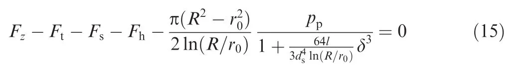
Since the thermal wedge bearing force(Ft),squeezing force(Fs),and hydrodynamic bearing force(Fh)are obtained,the values can be entered into Eq.(15),in which the film thickness is investigated.
3.3.Temperature-dependent viscosity model
The control volume of the fluid film within the slipper pair is subjected to two major heat sources:the heat coming from viscous dissipation associated with the fluid flow in the lubricating interfaces and the heat generated due to the rotations of the slipper and the swash plate in the oil-filled case.Thus,the conservation equation for energy is the basic equation for thermal-hydraulic modeling.For a lumped-parameter model and one-dimensional flow,there is a simplified representation of this equation.The governing equation is the expression of the energy conservation for an open system.The fluid volume is shown in Fig.4.The following equation applies for each control volume:

If the kinetic and potential energies are neglected,the time rate of change of the fluid energy can be expressed as follows:

whereEis the fluid energy,mis the fluid mass,anduis the fluid specific energy.
Since the fluids in this study do not change phase,the specific enthalpy can be expressed as a function of temperatureTand pressureps,that is,H=H(T,ps).Therefore,the enthalpy derivative can be expressed as
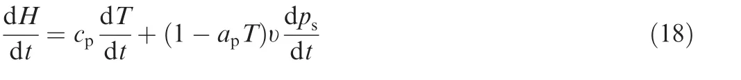
where υ is the specific volume andapis the expansion coefficient of the fluid.
This may be rearranged in terms of enthalpy as

Substituting Eqs.(18)and(19)in Eq.(17),Eq.(17)can be obtained as

whereVis the control volume.
The continuity equation for one-dimensional flow gives
Then the overall oil film temperature on the slipper pair can be calculated by
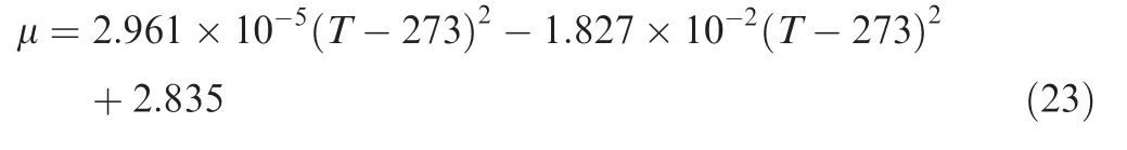
In addition,viscosity is one of the important factors that affect oil drive characteristics.Temperature has a considerable influence on oil viscosity.35,36In practice,energy dissipation in the lubricating film is not evenly distributed.Because of the very small film thickness in those small areas,the convection effect is limited through the limited leakage flow.Thus,the film gap of the slipper pair is simplified as a one-dimensional flow model,and then the oil viscosity is calculated.At present,ISO VG12 aviation hydraulic oil is usually used as the working medium for a pump,whose density is 900 kg/m3,and the dynamic viscosity is 0.018 Pa·s at 40 °C.At the same time,the viscosity-temperature relationship is measured as shown in Table 1.Since the experimental data are discrete temperature points,the temperature-dependent viscosity is written as
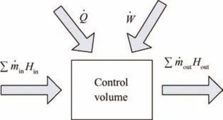
Fig.4 Schematic representation of the mass,heat,and work exchanged by a control volume.
Therefore,substituting Eq.(23)into Eqs.(8)and(9),the thermal wedge bearing force is investigated.
3.4.Heat transfer model
In this section,the heat transfer process between the oil film and the slipper pair in the axial piston pump is described.In order to select an appropriate heat transfer correlation during operation,the heat transfer regime of the slipper pair is specified.According to Fourier’law of heat conduction and Newton’s law of cooling,the heat transfer boundary for a considered oil film zone is described as shown in Fig.5.When fluid flows from the piston chamber into the slipper central chamber,the convective heat exchange between the fluid film and the slipper is written as34
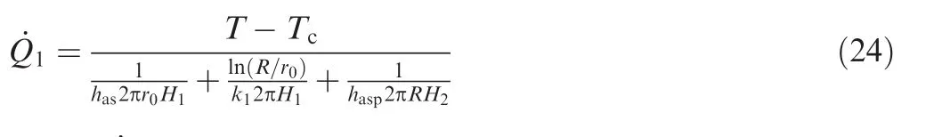
where˙Q1is the heat transfer rate of the slipper,Tcis the case temperature,H1is the slipper’s lug height,H2is the swash plate height,k1is the slipper thermal conductivity,hasis the convective heat transfer coefficient of the slipper,andhaspis the convective heat transfer coefficient of the swash plate.
The convective heat exchange between the fluid film and the swash plate is written as34

The convective heat exchange between the leakage fluid and the case fluid is calculated as follows:

Therefore,the total heat generation within the control volume of the fluid film through the heat transfer mode can be written as


Table 1 Viscosity-temperature relationship data.
Since the total heat generation within the control volume of the fluid film is obtained,the value can be substituted into Eq.(22),in which the oil film temperature is investigated.
3.5.Load-carrying model
When the oil film thickness is obtained from Eq.(15),the support force at the unit of oil film thickness can be calculated.Meanwhile,the support force that acts to resist the external load applied on the slipper,denotes the load-carrying capacity of the slipper pair.Thus,the load-carrying capacity of the slipper pair can be written as follows:
3.6.Numerical method
The schematic flow chart for film thickness and load-carrying capacity computations are described in Fig.6.A shaft revolution in the axial piston pump is simulated,solving in time at discrete intervals and corresponding to a progressively increasing shaft rotational angle and different load conditions.The aforementioned governing equations are simultaneously solved based on a numerical method.The slipper pocket pressure and slipper motion are obtained by the finite difference method for calculating the film thickness and load-carrying capacity.Once the slipper pocket pressure is obtained,the initial action forces applied on the slipper pair can be solved,such as the whole axial piston force applied on the slipper pair,hydraulic force,thermal wedge bearing force,squeezing force,and hydrodynamic bearing force.Oil film temperature and oil viscosity can be calculated based on the convective heat change process between the oil film and the slipper at each simulation step.At each shaft angle,not only the oil film temperature and oil viscosity variations are calculated,but also the initial action forces are changed,resulting in film thickness variation.At the last step,the load-carrying capacity of the slipper pair is predicted since the film thickness is given.The operation procedure continues to calculate the thermal equilibrium clearance over more shaft revolutions until the oil film temperature reaches a stable value.The process repeats until the rotational angle of shaft θ reaches the user defined value of or the simulation is terminated by the user.if the rotational angle of shaft θ is less than the user defined value of θmax,The external forces applied on the slipper pair corresponding to rotational angle of shaft are updated to obtain film thickness at the next step of rotational angle of shaft(θ=θ+Δθ).
4.Results and discussion
In this section,the effects of working conditions and slipper structural parameters on the film thickness and load-carrying capacity of the slipper pair will be studied.Therefore,the structural parameters of the slipper pair are shown in Table 2.The initial operating conditions and lubricant characteristics,such as input parameters,are listed in Table 3.
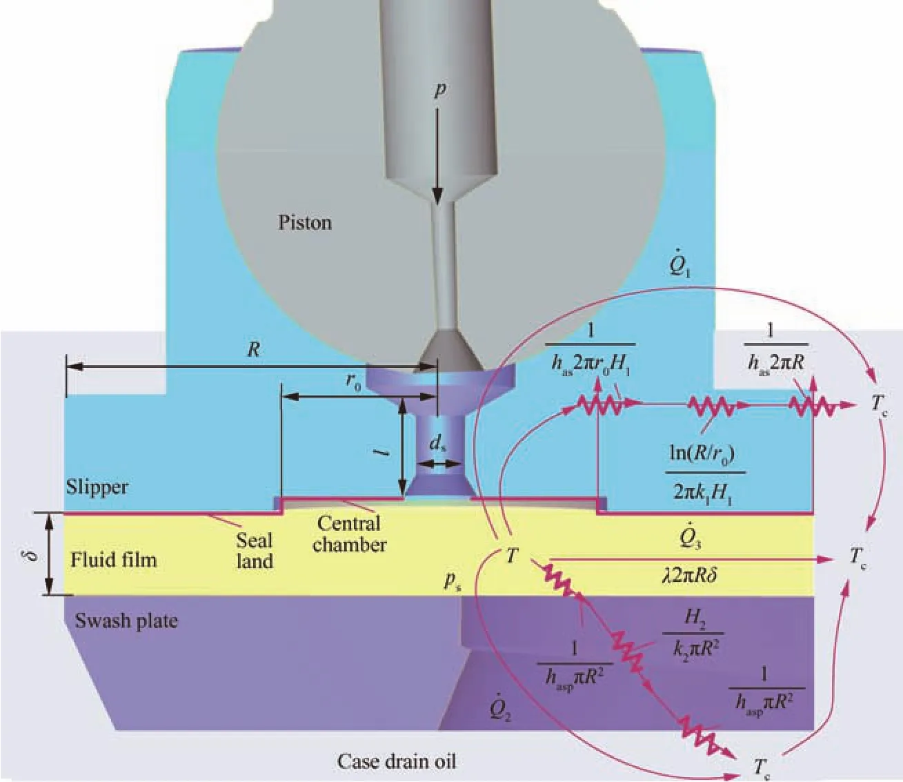
Fig.5 Heat exchange between solid parts and the hydraulic oil in the case.
4.1.Experimental validation
To validate the lubrication model of the slipper pair,an experimental rig was used to measure the film thickness and temperature as shown in Fig.7.A commercially manufactured 28-mL/r swash plate-type variable-displacement aviation axial piston pump was modified to directly measure the fluid film thickness and temperature,as shown in Fig.7(a).There are eight eddy current displacement sensors and four thermocouples,as shown in Fig.7(b).Each pair of sensors is circumferentially positioned at a 45°interval.For measuring the oil film thickness,the sensors were mounted on the swash plate along the motion trajectory of the slipper.The pitch diameter of the sensors’locations on the swash plate is 44.3 mm.To protect the eddy current sensor probes and ensure reliable running of the slipper,the eddy current sensors were mounted on the fixed swash plate with the offset installation method.The offset distance from the sensor probes to the swash plate face is 1 mm.The four thermocouples were inserted at the side wall of the swash plate along the pitch circle.They were circumferentially positioned respectively at 60°and 120°intervals for measuring the film temperature.Accuracy of the eddy current sensors is 0.1 μm,and the sampling frequency is 10 kHz.Accuracy of the thermocouples is±0.3°C,and the measurement range of temperature is 1–150 °C.The data acquisition system used to perform experiments,based on an NI compact DAQ module,is permitted to trigger film thickness and temperature acquisitions based on the signal provided by an FM multichannel transmitter fixed on the swash plate.The measured data were transferred to a data processing system through a telemetry device.In addition,the discrete points of measured film thickness and temperature were processed by the datasmoothing and curve- fitting toolboxes in Matlab.When the slipper runs heavily along the swash plate in high-and lowpressure phases,the film gap between the slipper and the swash plate is obtained from the differences in output signals of the sensors,as shown in Fig.7(c).The axial clearance is plotted as a function of time.The tested output signals of the axial clearance are obtained from sensors 2 and 7.The average values of the axial clearance are respectively 1.004 mm and 1.002 mm.The small amplitude means the actual film thickness between the slipper and the swash plate,and the value is within 0.002–0.004 mm.The tested output signals of temperature are obtained from sensors a2 and a3,as shown in Fig.7(d).Because sensor a2 is located at an angular position of 90°,where the viscous heat and the external clamping force acting on the slipper are relative high,the maximum film temperature is about 47 °C,which is about 3°higher than that measured by sensor a7 at an angular position of 270°.This can be attributed to the fact that the increase in the film temperature is due to the increase in the squeezing force generated in the slipper.Consequently,the pressure difference across the outlet boundary of the slipper increases,which results in a higher film temperature.
Fig.8 shows the variations of the average film thickness with a comparison between the experimental and simulation results.There are some differences between the simulation and experimental results for a particular value of the average film thickness,but the trends of the two curves are the same.The simulation result of the film thickness is always lower than the experimental result.The minimum value of the average fluid film thickness calculated by the theoretical result during a delivery stroke is about 1 μm higher than the measured result,but the maximum value obtained from the theoretical result during a suction stroke is about 4 μm lower than the measured result.The predicted film thickness is lower than the measured result because most of the heat was taken away by heat conduction between the slipper and the oil film.These changes are due to the dissipation of the heat flux generated in the fluid film because of the large volume of the gap.In fact,the mechanical viscous dissipation is a direct consequence of fluid film geometry and fluid flow velocities.As described previously,the heat generated in the fluid film due to viscous dissipation is the most critical boundary to the thermal models of the solid parts.Therefore,a precise calculation of the fluid film boundary’s temperature is a measure of accuracy in the prediction of fluid film thickness and slipper motion during one shaft revolution.Moreover,the experimental result of the average film thickness decreases at first and then increases during a delivery stroke(0°–180°).This phenomenon can be explained by the external clamping force acting on the slipper and the change rate of the film thickness.The practical installation position of each eddy current sensor should be reminded,where a concave trough is formed that is easy to store lubricant fluid.On the other hand,the average film thickness difference reflects the tilting state of the slipper.Furthermore,the tilting angle of the slipper due to a hydrodynamic effect becomes gradually higher than the calculated result during a suction stroke(180°–360°),which leads to increasing the measured film thickness.

Fig.6 Schematic flow chart for computations of the loadcarrying capacity of the slipper pair.
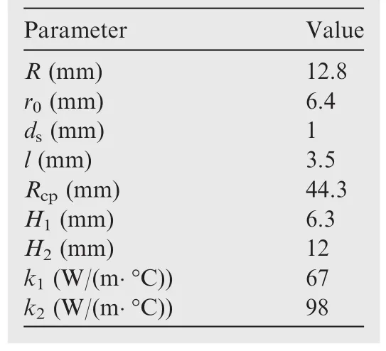
Table 2 Structural parameters of the slipper pair.
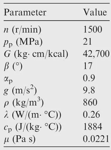
Table 3 Input parameters of the model.
Fig.9 shows the variations of the oil film temperature with a comparison between the measured and simulated results.For the experiment,during a delivery stroke,the film temperature increases from 45 °C to 51 °C,whereas the simulation prediction is increased from 48.5 °C to 50.5 °C during a delivery stroke.The variation in temperature across the oil film is large,which leads to increasing the viscous heat at the film gap between the slipper and the swash plate.The maximum value of fluid film temperature during a delivery stroke is about 1–2°C lower than the measured value.Comparing Figs.8 and 9,the higher film temperature corresponds to the lower average film thickness.During a delivery stroke,the average value of fluid film thickness is lower in this region and the viscous heat is large,generating a localized high-temperature area.The effects of thermal dissipation of the slipper actually worsen the described condition,further reducing the fluid film.This result is due to the fact that severe loads are applied on the slipper during high-pressure operations,so the viscous friction of the slipper pair becomes gradually higher with increasing load pressure,which leads to more heat generation.The average value of oil film thickness becomes thinner due to the squeeze effect during the discharge pressure zone,and viscous heat within the fluid film is more obvious.In addition,the measured and simulated results of film temperature decrease gradually during a suction stroke,because there is almost no pressure difference at the slipper pair,but the hydrodynamic effect is more notable,which leads to decreasing the energy dissipation of the slipper pair,and most of the heat is taken away by the lubricant.

Fig.7 Experimental rig to measure the film thickness and temperature.
4.2.Effect of oil temperature
Fig.10 illustrates the effect of temperature on the average film thickness.During a delivery stroke,the average film thickness is lower than that during a suction stroke.As the oil temperature increases from 50 °C to 90 °C,there is a prominent decrease in the average thickness of the lubricating oil film during a suction stroke.Especially when the oil temperature is 90°C,the oscillation amplitude of the average film thickness becomes smaller in the transition region,which in turn implies the breaking of the oil film.Two factors contribute to this influence,the squeezing force and the thermal wedge bearing force acting on the slipper.The squeezing force increases dramatically as the oil temperature increases from 50 °C to 90 °C.At the same time,the thermal wedge bearing force becomes higher,which leads to increasing the viscous heat generation at the film gap between the slipper and the swash plate.These factors result in generating a high clamping force acting on the slipper that causes the film thickness decrease.For high-oil temperature conditions,the slipper is unable to find equilibrium due to the high thermal wedge bearing force,and the variation of the oil film thickness is not compromised while the slipper is strongly unstable.
Fig.11 shows the effect of temperature on the load-carrying capacity of the slipper pair.The load-carrying capacity of the slipper pair periodically changes with the shaft angle and increases as the film temperature increases.The maximum load-carrying capacity of the slipper pair occurs at angles from 0°to 180°.As the oil temperature increases from 50 °C to 90°C,the average maximum load-carrying capacity of the slipper pair increases from 200 N/μm to 500 N/μm.The physics phenomenon is related to the film stiffness that is defined as the gradient of the load-carrying capacity.This film stiffness changes with different film temperatures.As the film thickness decreases,the load-carrying capacity for high oil temperature increases faster than that for low oil temperature,implying that the film stiffness increases as the temperature increases.There are two factors that affect the load-carrying capacity,which are the film thickness and the oil viscosity.During delivery strokes,the load-carrying capacity increases with a high decline in the film thickness,while decreasing the fluid viscosity increases the load-carrying capacity.As the film thickness drops,the temperature increases rapidly,the oil viscosity drops,and the overall result is a rather high increase in the load-carrying capacity.
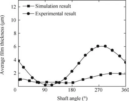
Fig.8 Average film thickness comparison between simulation and experimental results.

Fig.9 Average film temperature comparison between simulation and experimental results.

Fig.10 Effect of the temperature on the average film thickness.
In order to illustrate the influences of external forces on the load-carrying capacity and film thickness of the slipper pair under different temperatures,the external forces acting on the slipper pair during delivery and suction strokes are given in Table 4,such as the thermal wedge bearing force,squeezing force,and hydrodynamic bearing force.The relationships among the film thickness,load-carrying capacity,and external forces are presented.When the fluid temperature increases from 50 °C to 90 °C,the squeezing force decreases from 1350 N to 220 N during delivery strokes(φ=120°),but the film thickness decreases from 0.67 μm to 0.1 μm.It can be found that the film thickness becomes thinner but the loadcarrying capacity increases,while the maximum external force applied on the slipper occurs at delivery strokes.This result can be explained that the squeezing force increases sharply with a high decline in oil viscosity due to high oil temperature during the discharge pressure zone,which leads to decreasing the film thickness.Then,the load-carrying capacity of the slipper pair begins to increase with increasing the clamping force due to the combined action of the squeezing force and the thermal wedge bearing force,as well as the decreasing thickness of the lubricating oil film.In addition,during suction strokes(φ=240°),the load-carrying capacity of the slipper pair decreases as the thickness of the film becomes greater.This can be attributed to the fact that the thermal wedge bearing force and hydrodynamic bearing force are inversely proportional to the thickness of the lubricating oil film.For the low-pressure phase,in which the angular position of the slipper is at 240°,the value of the squeezing force is negative due to the squeezing velocity for the film thickness in a reverse direction.The reason for this may be explained by considering that the squeezing force is proportional to the variation rate of the film gap(-dδ/dt)but inversely proportional to 1/δ3.
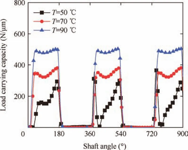
Fig.11 Effect of the temperature on the load-carrying capacity of the slipper pair.

Table 4 Relationships among external forces,load-carrying capacity,and film thickness under different temperatures.
4.3.Effect of load pressure
Fig.12 illustrates the variations of the average film thickness with different load pressures.During the high-pressure phase(0–180°),the average film thickness is lower than that during the low-pressure phase.Moreover,the higher the load pressure is,the lower the average thickness of the film gap becomes during the high-pressure phase.It can be explained that,at a higher load pressure,the average film thickness is slightly lower during both the high-pressure and low-pressure phases,because of the enhanced thermal effect.The thermal effect generation is contributed to the fact that the squeezing force and thermal wedge bearing force are relatively high in the transition region,which leads to decreasing the average film thickness.In addition,the average film thickness is higher and the slipper has to run heavily tilted to enhance the hydrodynamic lift during the low-pressure phase(180°–360°).
Fig.13 illustrates the influence of load pressure on the loadcarrying capacity of the slipper pair.When the load pressure increases form 21 MPa to 28 MPa,the maximum loadcarrying capacity increases from 200 N/μm to 300 N/μm,which occurs at the high-pressure phase.The load-carrying capacity of the slipper pair during a delivery stroke is larger than that during a suction stroke.Referencing to Fig.12,as the minimum film thickness increases,the stiffness for all load pressure is relatively low.As the film thickness increases,the load-carrying capacity for the high-load pressure curve increases faster than that for the low-load pressure curve,implying that any small variation in the load pressure will result in significant variations in the film thickness as well as the film stiffness.Especially,the load-carrying capacity of the slipper pair changes unsteadily due to the thermal effect,and there is load pressure overshoot in the transition region.The reason is that the squeezing force and the thermal wedge force change with respect to the angular position,while the load pressure only increases or decreases in the transition region.As the slipper transits from high pressure to low pressure,the clamping force due to the squeezing force and thermal wedge force is the maximum,and then it leads to increasing the peak value of film stiffness,as well as decreasing the thickness of the oil film.The change rate of the film thickness is positive when the external clamping force increases,and the film thickness starts to decrease,which leads to increasing the loadcarrying capacity.

Fig.12 Effect of the load pressure on the average film thickness.

Fig.13 Influence of the load pressure on the load-carrying capacity of the slipper pair.
In order to illustrate the influences of external forces on the load-carrying capacity and film thickness under different load pressures,the external forces respectively are given at shaft angles of 120°and 240°,such as the thermal wedge bearing force,squeezing force,and hydrodynamic bearing force.As shown in Table 5,the load-carrying capacity increases with increasing load pressure.This increase in the load-carrying capacity with the load pressure is not linear.It can be explained that when the load pressure increases from 21 MPa to 28 MPa,the maximum thermal wedge bearing force of the slipper pair increases from 2600 N to 3340 N,and the squeezing force increases from 1350 N to 1686 N,but the hydrodynamic bearing force remains the same,which leads to decreasing the film thickness during the high-pressure phase.As the load pressure increases,the squeeze bearing force of the oil film may offset part of the clamping force,which leads to decreasing the film thickness.As the oil film thickness decreases,the thermal wedge force increases rapidly due to thermal expansion within the oil film until it reaches a new force balance position of the slipper pair.There are two factors that affect the load-carrying capacity,which are the squeezing force and thermal wedge bearing force.Decreasing the film thickness increases the load-carrying capacity,while increasing the load pressure decreases the film thickness.As mentioned above,at relatively high load pressure,the combined action of the squeezing force and thermal wedge bearing force does help a lot to increase the load-carrying capacity.
4.4.Effect of shaft rotational speed
Fig.14 illustrates the variations of the average film thickness with different shaft rotational speeds.The film thickness as a function of the shaft angle is depicted at the same rotational speed.It shows an oscillatory trend which is emphasized at high rotational speed.When the shaft rotational speed increases from 1500 r/min to 9000 r/min,the ripple amplitude of the film thickness increases from 0.2 μm to 2 μm.This is as much evident as the hydrodynamic effect generated by the slipper’s tilting movement.The hydrodynamic bearing force of the slipper pair increases with increasing shaft rotational speed,which does cause the majority of hydrodynamic lift.For high shaft rotational speed,hydrodynamic lift is more obvious as the hydrodynamic bearing force acting on the slipper increases,resulting in a high ripple amplitude of the average film thickness.In particular,for a shaft rotational speed of 9000 r/min and a load pressure of 21 MPa,as the slipper runs in a suction stroke,the sudden increase in the hydrodynamic pressure is reflected immediately with a sharp increase in the ripple amplitude of the average film thickness.
Fig.15 shows the effect of the shaft rotational speed on the load-carrying capacity of the slipper pair.It is found that as the shaft rotational speed increases from 1500 r/min to 9000 r/min,the load-carrying capacity of the slipper pair decreases from 600 N/μm to 200 N/μm,which occurs in suction strokes.Meanwhile,the higher the ripple amplitude of the average film thickness is,the lower the load-carrying capacity of the slipper pair is.These results are due to the facts that the hydrodynamic bearing force of the slipper pair increases with increasing the shaft rotational speed,which leads to increasing the average film thickness,and finally results in a lower loadcarrying capacity of the slipper pair.Moreover,comparing Figs.14 and 15,the ripple amplitude of the average film thickness is so obvious that it decreases the load-carrying capacity at high-shaft rotational speed conditions.From the analysis above,it is quite clear that the slipper cannot guarantee a good load-carrying capacity when the shaft rotational speed is 9000 r/min.This unstable behavior can result in adhesive wear of the slipper pair occurring on the local contact surface and inadequate efficiency of the axial piston pump.

Fig.14 Effect of the shaft rotational speed on the average film thickness.
In order to examine the effects of external forces on the load-carrying capacity and film thickness under different shaft rotational speeds,the load-carrying capacity and film thickness are listed in Table 6.When the shaft rotational speed increases from 5000 r/min to 9000 r/min,the thickness of the lubricating oil film at a shaft angle of 120°increases from 0.97 μm to 1.76 μm,which is lower than that at a shaft angle of 240°.Moreover,the load-carrying capacity of the slipper pair is inversely proportional to the thickness of the lubricating oil film.This result can be explained by that the hydrodynamic bearing force is proportional to the slipper velocity(v)but inversely proportional to 1/δ2.Especially,with increasing shaft rotational speed,the film thickness is slightly higher during both the high-pressure and low-pressure phases,because of enhanced hydrodynamic lift,and the final result is that the load-carrying capacity decreases sharply in this condition.What’s more,the thermal wedge force is proportional to the slipper velocity(v)but inversely proportional to 1/δ2.As mentioned above,the sum of the thermal wedge force and hydrodynamic force pulls the slipper away from the swash plate,andthen it helps in pushing the slipper against the swash plate in a suction stroke.
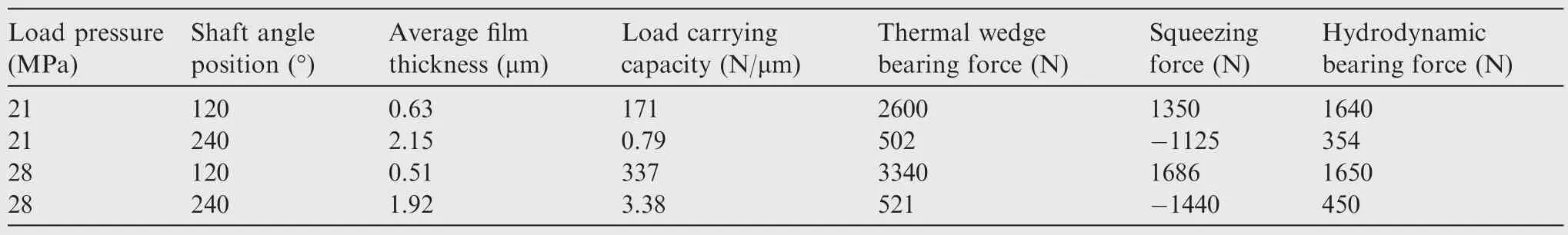
Table 5 Relationships among external forces,load-carrying capacity,and film thickness under different load pressures.
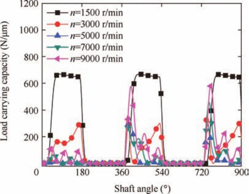
Fig.15 Effect of the shaft rotational speed on the load-carrying capacity of the slipper pair.
4.5.Parameter influence
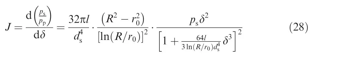
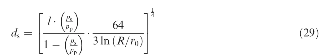
The film thickness and load-carrying capacity of the slipper pair represent the important characteristics of the pump performance;however,they may be affected by different parameters such as the orifice diameterds,the orifice lengthl,the slipper inner radiusr0,and the slipper outer radiusR.In addition,the slipper radius ratio is defined as the ratio of the slipper inner radius to the slipper outer radius,which influences the sealing land area of the slipper.The orifice length diameter ratio is defined as the ratio of the orifice diameter to the orifice length,which influences the slipper pocket pressure.Thus,the influences of these parameters are investigated in this section and the results may help in better designing a slipper like the one shown in Fig.1.To ensure the load-carrying capacity of the slipper pair,the chosen seizure of the orifice diameter needs to be caudated.Therefore,Eq.(14)can be written as
To examine the influence of the slipper radius ratio on the average film thickness and load-carrying capacity,all the structural parameters of the slipper specified in Tables 2 and 3 are kept the same except that the slipper inner radius is changed to 6.3 mm,7 mm,7.8 mm,9 mm,and 10.5 mm.In other words,the slipper radius ratio is changed to 1.2,1.4,1.6,1.8,and 2.0.Fig.16 shows the effect of the slipper radius ratio on the average film thickness and load-carrying capacity.It can be seen that the film thickness decreases rapidly with increasing slipper radius ratio,but the load-carrying capacity becomes larger.This is because as the slipper radius ratio increases,there is less hydrodynamic bearing force on the sealing land area of the slipper but higher squeezing bearing force,resulting in film thickness reduction.With an increase of the squeezing bearing force,the average film thickness becomes thinner,which results in breaking of the lubricating oil film and abrasion wear of the slipper.Thus,although the load-carrying capacity of the slipper pair increases,there is no benefit of making the slipper radius ratio larger than that corresponding to the minimum value of the average film thickness.To take advantage of the hydrodynamic bearing force and squeezing bearing force,the slipper radius ratio should be selected from1.4 to 1.8.
In these numerical simulations,the orifice length is kept the same,and the orifice diameter is changed to 1.75 mm,0.98 mm,0.8 mm,0.6 mm,and 0.4 mm.In other words,five orifice length diameter ratios are tested:2.0,3.56,4.37,5.83,and 8.75.Fig.17 shows the effect of the orifice length diameter ratio on the average film thickness and load-carrying capacity.In Fig.17,it can be found that the average film thickness drops as the orifice length diameter ratio increases,but the loadcarrying capacity increases.Two factors contribute to this influence,the squeezing bearing force and the pressure drop along the orifice.As the orifice length diameter ratio increases,the pressure drop along the orifice increases,which leads to a high squeezing force generation,and results in a film pressure buildup reduction.Thus,the orifice length diameter ratio is very important in determining the load-carrying capacity of the slipper pair.For a low orifice length diameter ratio,the average film thickness increases,but at the same time,the load-carrying capacity will also decrease.For a high orifice length diameter ratio,the average film thickness becomes thinner,but the load-carrying capacity will increase sharply.Considering all the above issues,it may be recommended that the orifice length diameter ratio should be selected from 4 to 5.
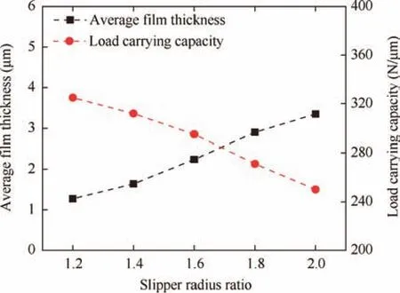
Fig.16 Effect of the slipper radius ratio on the average film thickness and load-carrying capacity.
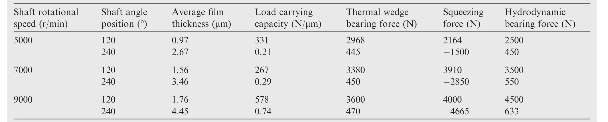
Table 6 Relationships among external forces,load-carrying capacity,and film thickness under different shaft rotational speeds.

Fig.17 Effect of the ori fice length diameter ratio on the average film thickness and load-carrying capacity.
5.Conclusions
This paper presents a thermal hydraulic model to analyze the load-carrying capacity of a slipper pair in an aviation axialpiston pump based on the lumped parameter method in view of temperature,load pressure,and shaft rotational speed.The model is capable of predicting the film temperature,film thickness,and load-carrying capacity of the slipper pair.A parametric study is conducted for the slipper’s structural parameter optimization and its performance evaluation.Both theoretical analysis and experimental results demonstrate the validity of the thermal hydraulic model.From the results presented in this paper,the following conclusions can be drawn:
(1)The film thickness and load-carrying capacity are affected by the oil temperature.As the oil temperature increases,the film thickness decreases,but the loadcarrying capacity will increase dramatically.The squeezing force and thermal wedge bearing force are main factors that affect the film thickness and load-carrying capacity.At high oil temperature,there is high viscous dispassion at the film gap,which leads to increasing the thermal wedge bearing force.Because the combined action of the squeezing force and the thermal wedge bearing force becomes larger,the film thickness decreases with increasing clamping force,but the loadcarrying capacity of the slipper pair will increase.
(2)Higher load pressure may result in thinner film thickness.The reduction in the film thickness is due to the increase in the clamping force generated on the slipper when the load pressure increases.What’s more,as the film thickness decreases,the thermal wedge force increases rapidly due to thermal expansion within the oil film until it reaches a new force balance position of the slipper pair,which leads to increasing the loadcarrying capacity.
(3)An increase of the film thickness is proven to be beneficial under high shaft rotational speed but especially dangerous under high shaft rotational speed as it strongly increases the ripple amplitude of the film thickness,which leads to decreasing the load-carrying capacity.The ripple amplitude of the film thickness is related to the hydrodynamic lift that is caused by the hydrodynamic bearing force.The higher the shaft rotational speed is,the larger the hydrodynamic bearing force along the bottom of the slipper becomes.At high shaft rotational speed,because of enhanced hydrodynamic lift,the final result is that the load-carrying capacity decreases sharply in this condition.
(4)The slipper radius ratio and orifice length diameter ratio have significant influences on the film thickness and load-carrying capacity behaviors.If the slipper radius ratio increases,the film thickness decreases,but the load-carrying capacity will increase sharply.As the slipper radius ratio increases,there is higher squeezing bearing force on the sealing land area of the slipper,resulting in thinner film thickness.Although the load-carrying capacity of the slipper pair increases,there is no benefit of making the slipper radius ratio larger than that corresponding to the thinner film thickness.To take advantage of the squeezing bearing force,the value of the slipper radius ratio should be selected from 1.4 to 1.8.As the orifice length diameter ratio increases,the film thickness decrease due to a higher squeezing bearing force,but at the same time,the load-carrying capacity will also decrease.Considering all the above issues,it may be recommended that the orifice length diameter ratio should be selected from 4 to 5.
Acknowledgements
This paper was co-supported by the National Natural Science Foundation of China(No.51505338 and No.51475332)and the Youths Science Foundation of Zhejiang (No.LQ16E050004 and No.LQ17E050003).
1.Zawistowski T,Michał K.Gap flow simulation methods in high pressure variable displacement axial piston pumps.Arch Comput Methods Eng2016;24(4):1–24.
2.Xu B,Ye SG,Zhang JH.Numerical and experimental studies on housing optimization for noise reduction of an axial piston pump.Appl Acoust2016;110(9):43–52.
3.Xu B,Ye SG,Zhang JH,Zhang CF.Flow ripple reduction of an axial piston pump by a combination of cross-angle and pressure relief grooves:analysis and optimization.J Mech Sci Tech2016;30(6):2531–45.
4.David R,Farshid S,Richard GRJ,Scott R.Experimental and analytical investigation of floating valve plate motion in an axial piston pump.Tribol Trans2016;5(2):1–12.
5.Koc E,Hooke CJ.Investigation into the effects of orifice size,offset and overclamp ratio on the lubrication of slipper bearings.Tribol Int1996;29(4):299–305.
6.Kazama T,Yamaguchi A.Experiment on mixed lubrication of hydrostatic thrust bearings for hydraulic equipment.J Tribol1995;117(3):399–402.
7.Harris RM,Edge KA,Tilley DG.Predicting the behaviour of slipper pads in swash plate–type axial piston pumps.J Dyn Sys Meas Control1996;118(1):41–7.
8.Borghi M,Specchia E,Zardin B.Numerical analysis of the dynamic behaviour of axial piston pumps and motors slipper bearings.SAE Int J Pass Cars-Mech Syst2009;2(1):1285–302.
9.Lu HL,Jian K,Wang GZ,Yang LY.Research on the lubrication characteristics of water hydraulic slipper friction pairs.J Mech Eng Sci2011;220(10):1559–67.
10.Murrenhoff H,Scharf S.Wear and friction of ZRCG-coated pistons of axial piston pumps.Int J Fluid Power2014;7(3):13–20.
11.Deeken M.Simulation of the tribological contacts in an axial piston machine.Proceedings of ASME international mechanical engineering congress and exposition;2004.p.1–5.
12.Canbulut F,Koc E,Sinanoglu C.Design of artificial neural networks for slipper analysis of axial piston pumps.Ind Lubr Tribol2009;61(2):67–77.
13.Manring ND,Wray CL,Dong Z.Experimental studies on the performance of slipper bearings within axial-piston pumps.J Tribol2004;126(3):511–8.
14.Nie SL,Huang GH,Li YP.Tribological study on hydrostatic slipper/swash plate pair with annular orifice damper for water hydraulic axial piston motor.Tribol Int2006;39(2):1342–52.
15.Bergada J,Watton J,Haynes J,Davies D.The hydrostatic/hydrodynamic behavior of an axial piston pump slipper with multiple lands.Meccanica2010;45(4):585–602.
16.Bergada JM,Haynes JM,Watton J.Leakage and groove pressure of an axial piston pump slipper with multiple lands.Tribol Trans2008;51(4):469–82.
17.Kumar S,Bergada JM,Watton J.Axial piston pump grooved slipper analysis by CFD simulation of three-dimensional NVS equation in cylindrical coordinates.Comput Fluids2008;39(6):648–63.
18.Ma JM,Chen J,Li J,Li QL,Ren CY.Wear analysis of swash plate/slipper pair of axis piston hydraulic pump.Tribol Int2015;90(5):467–72.
19.Chen J,Ma JM,Li J,Fu YL.Performance optimization of grooved slippers for aero hydraulic pumps.Chin J Aeronaut2016;29(3):814–23.
20.FaridAyada A,Abdallaa M,AbouEl-Azm AA.Effect of semiopen impeller side clearance on the centrifugal pump performance using CFD.Aerosp Sci Technol2015;47(3):247–55.
21.Lin S,Hu JB.Tribo-dynamic model of slipper bearings.Appl Math Model2015;39(3):548–58.
22.Kazama T.Thermohydrodynamic lubrication model applicable to a slipper of swash plate type axial piston pumps and motors(effects of operating conditions).Tribol Online2010;5(2):250–4.
23.Kazama T,Suzuki M,Suzuki K,Narita Y,Sakurai S.Simultaneous measurement of sliding-part temperature and clearance shape of a slipper used in swash plate type axial piston Motors.Trans Japan Hydraul Pneumat Soc2014;45(1):22–8.
24.Yang ZB,Chen XF,Xie Y,Zuo H,Miao HH,Zhang XW.Wave motion analysis and modeling of membrane structures using the wavelet finite element method.Appl Math Model2016;40(3):2407–20.
25.Zhang X,Zuo H,Liu J,Chen X,Yang Z.Analysis of shallow hyperbolic shell by different kinds of wavelet elements based on B-spline wavelet on the interval.Appl Math Model2016;40(2):1914–28.
26.Ivantysynova M,Huang C.Investigation of the gap flow in displacement machines considering the elastohydrodynamic effect.The fifth JFPS international symposium on fluid power;2002.p.219–29.
27.Schenk A,Ivantysynova M.A transient thermoelastohydrodynamic lubrication model for the slipper/swash plate in axial piston machines.J Tribol2015;137(3):1–10.
28.Shang L,Ivantysynova M.Port and case flow temperature prediction for axial piston machines.Int J Fluid Power2015;16(1):35–51.
29.Hashemi S,Kroker A,Boobach L,Bartel D.Multibody dynamics of pivot slipper pad thrust bearing in axial piston machines incorporating thermal elastohydrodynamics and mixed lubrication model.Tribol Int2016;96(3):57–76.
30.Xu B,Zhang JH,Yang HY.Investigation on structural optimization of anti-overturning slipper of axial piston pump.Sci China Tech Sci2012;55(3):3011–8.
31.Xu B,Wang QN,Zhang JH.Effect of case drain pressure on slipper/swashplate pair within axial piston pump.J Zhejiang Univ-Sci A(Appl Phys&Eng)2015;16(12):1001–14.
32.Tang HS,Yin YB,Zhang Y,Li J.Parametric analysis of thermal effect on hydrostatic slipper bearing capacity of axial piston pump.J Central South Univ2016;23(2):333–43.
33.Tang HS,Yin YB,Li J.Lubrication characteristics analysis of slipper bearing in axial piston pump considering thermal effect.Lubr Sci2016;28(2):107–24.
34.Wen DS.Innovation and development of hydraulic components.Beijing:Aviation Industry Press;2009[Chinese].
35.Yang LJ,Nie SL,Zhang AQ.Non-probabilistic wear reliability analysis of swash-plate/slipper of water hydraulic piston motor based on convex model.Proc IMechE Part C:J Mech Eng Sci2012;227(3):609–19.
36.Kazama T,Suzuki M,Suzuki K.Relation between sliding-part temperature and clearance shape of a slipper in swashplate axial piston motors.The ninth JFPS international symposium on fluid power;2014.p.1–8.
杂志排行

CHINESE JOURNAL OF AERONAUTICS的其它文章
- A self-similar solution of a curved shock wave and its time-dependent force variation for a starting flat plate airfoil in supersonic flow
- Robust Navier-Stokes method for predicting unsteady flowfield and aerodynamic characteristics of helicopter rotor
- Effects of trips on the oscillatory flow of an axisymmetric hypersonic inlet with downstream throttle
- Development of a coupled supersonic inlet-fan Navier–Stokes simulation method
- An equilibrium multi-objective optimum design for non-circular clearance hole of disk with discrete variables
- Shock/shock interactions between bodies and wings