Fault diagnosis of an intelligent hydraulic pump based on a nonlinear unknown input observer
2018-03-21ZhonghaiMAShaopingWANGJianSHITongyangLIXingjianWANG
Zhonghai MA,Shaoping WANG,Jian SHI,Tongyang LI,Xingjian WANG
School of Automation Science and Electrical Engineering,Beihang University,Beijing 100083,China
1.Introduction
A hydraulic pump is the key component in an aircraft hydraulic system,on whose operating performance the quality of the pump has an important impact.In order to meet those requirements of modern aircraft,such as high speed,high mobility,low weight,and high load capacity,the intelligent hydraulic pump system(IHPS)has been paid more and more attention to for improving the efficiency of an aircraft hydraulic system.An aircraft hydraulic system with an IHPS has become an important future development direction,1–3and the requirements for reliability and security also grow significantly,4which implies that an efficient fault diagnosis will improve the reliability of the IHPS significantly.
An IHPS is generally defined as a kind of pump source system whose output can be easily controlled by the virtue of an intelligent controller to meet those requirements of an actual aircraft hydraulic system.To realize feedback control of the output,necessary sensors are installed on an IHPS,including pressure sensors,displacement sensors,and temperature sensors.5Based on an IHPS’s state parameters and its actual operating condition,the controller adjusts the displacement of the pump in accordance with the pressure signal,and then achieves optimal matching with the load.The advantage of an IHPS is that,under the conditions of different aircraft flight statuses and commands from the flight control computer,the output of the IHPS can match the load reasonably.Thereby,an IHPS can reduce the invalid power and heat of an aircraft hydraulic system to improve the aircraft’s work efficiency.6Up to now,a lot of research on the structure design of an IHPS has been done.7–9Ma et al.proposed a new type of axial piston variable displacement pump,7which was an improvement on the basis of an A4V pump and used a servo valve to control the variable mechanism directly.This improved pump can sense the load correctly and timely based on the output pressure command of the intelligent pump controller,and can provide necessary information for monitoring the pump operating condition and fault diagnosis.8However,this intelligent pump is more complex than a traditional hydraulic pump in structure.Comparing to a traditional hydraulic pump,an IHPS installs many additional sensors to attain pump state signals.10Furthermore,an IHPS integrates a servo valve to control the pump variable mechanism,so as to realize servo control.9The complex structure has made the structure design and signal processing of the IHPS a tough job,11,12and the failure probability of the IHPS also increases with a dynamic change of the operating condition.Some previous studies have been mainly focused on the fault diagnosis of a common piston pump.Lu et al.presented a fault diagnosis method of piston pumps using a pump discharge pressure signal.13Wang and Hu proposed a vibration-signals-based fault diagnosis method using the fuzzy technique.14Some artificial neural network(ANN)models have also been widely applied to pump fault diagnosis considering their nonlinearity,adaptability,and robustness.15Lu et al.presented a diagnosis method for hydraulic pumps based on the chaotic parallel radial basis function(RBF)network.16
These above methods have been proven to be effective for piston-pump fault diagnosis to a certain extent.However,many limitations still exist obviously in these methods,which becomes pretty severe especially when we apply these methods to IHPS fault diagnose.Due to structural complexity and flexible operation conditions,the mechanism of IHPS failure is more complicated,and the fault detection and diagnosis for an IHPS is more difficult.Comparing to common variable pumps,the working modes of an IHPS switch more frequently.According to a real aircraft flight profile,an IHPS would switch its operation within four kinds of different working modes,that is,constant pressure mode,constant flow mode,constant power mode,and load sensitive mode.17The outputs of flow and pressure in each mode are totally different,which will obviously increase the fatigue and aging of the reset spring,as well as the wear of the variable cylinder of the pump.In such situations,the swashplate angle cannot be adjusted with a command signal,and a flow regulation of the IHPS cannot be performed.Furthermore,the leakage due to the wear of three friction pairs(swashplate and slipper,valve plate and cylinder block,and piston and cylinder bore)becomes more complex,in which the aging of sealing elements and the failure of the connection between the shaft and the roller bearing should be considered.18When it comes to the two aforementioned common faults of an IHPS,traditional fault diagnosis methods are not feasible for the analysis of intelligent pumps.8,19On one hand,due to long life cycles and actual complex flight conditions,it is difficult to obtain a large quantity of faulty pump samples and fault data.Therefore,the expert knowledge of pump failure is not perfect,and it brings difficulties to an accurate fault diagnosis based on artificial intelligence which needs long-term practical experience and a large quantity of fault information.20–22On the other hand,because of its severe working environment,the slowly varying fault value of leakage and aging may be overwhelmed by environmental noise and cannot be separated from the environmental interference.The dynamic change of various conditions leads to complex fault characteristic signals,which are difficult to analyze with a signal-based diagnosis method using a fixed threshold.23–25Therefore,it is urgent to find an effective fault diagnosis method which is suitable for the complex technical characteristics of an IHPS to ensure its reliable operation.
In this paper,to achieve higher reliability and security and improve the performance of an IHPS,a fault diagnosis method based on a nonlinear unknown input observer(NUIO)is proposed to realize IHPS fault detection.Different from factors of a full-order Luenberger-type unknown input observer presented by Chen et al.and Duan et al.26,27nonlinear factors of the IHPS are considered.By comparing the measured signals of the object to be diagnosed and the prior information of the system expressed by a model,a residual error is generated by utilizing a NUIO,and then the residual error is analyzed and processed to realize fault diagnosis.28Based on analysis of IHPS working mechanism and typical failure modes,an accurate nonlinear mathematical model of the IHPS is established.Then,a dynamic fault diagnosis method based on dynamic characteristics and variability of the signals is proposed.29,30Finally,based on the MATLAB simulation platform,the simulation analysis of two typical failure modes of the IHPS is carried out,and the results verify the validity and accuracy of this fault diagnosis method.
The remaining part of this paper is organized as follows.In Section 2,a mathematical model of an IHPS is established considering the working mechanism and failure modes.Section 3 presents the IHPS NUIO on the basis of output pressure and swashplate angle signals.Section 4 carries out model based fault diagnose based on the NUIO for typical failure modes of the intelligent pump according to detailed parameters.Section 5 gives conclusions.
2.Mechanism analysis of an intelligent pump
2.1.Structure and operational mechanism of an intelligent pump
A conventional axial piston pump,as shown in Fig.1,is widely used to provide constant high-pressure oil to manipulate an outside load,which leads to power dissipation under a smallload demand.Therefore,an intelligent pump appears,which consists of a reciprocating cylinder swashplate,an embedded control circuit,and a servo variable mechanism.The variable displacement pump of the IHPS is controlled by a microcomputer through a feedback signal.The control circuit accepts the command from the flight computer according to the flight profile and controls the angle of the swashplate to get appropriate flow.This kind of design can make the intelligent pump provide a flow dynamically according to the load demand in order to save energy.In addition,the intelligent pump can also give an appropriate failure treatment when a failure happens.The core of the IHPS is a variable displacement pump controlled by a microcomputer,which makes it adaptable to various load requirements,capable of dealing with fault states,and have good transient response ability.This adaptive adjustment of the swashplate overcomes the throttling loss of a traditional axial piston pump under constant pressure,and reduces the invalid power and heat of an aircraft hydraulic system.31In order to figure out the dynamic characteristics of the intelligent pump,it is necessary to establish its mathematical model and analyze its dynamic performance.
The theoretical flow of the intelligent pumpQtis related to the area of a piston,the number of pistons,the swashplate angle,and the speed of the pump as follows:

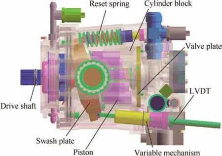
Fig.1 A certain type of intelligent pump.
wheredis the diameter of a piston,Zis the number of pistons,nis the speed of the pump,γ is the angle of the swashplate of the pump,andris the radius of the piston distribution circle.The theoretical flowQtis nonlinear with the angle of the swashplate γ.
Based on Eq.(1),the theoretical angular displacementqt(γ)with respect to the angle of the swashplate γ can be expressed as

In order to adjust the output flow of the intelligent pump dynamically,the variable mechanism controlled by the embedded microcomputer is shown in Fig.2.As shown in Fig.2,the motor provides a torqueMto drive the hydraulic pump,and the output pressure of the systemPsand the load pressure of the systemPLcan be measured by pressure sensors respectively,while the temperatures of the system are also obtained by three temperature sensors.The displacement of the swashplate is measured by a LVDT(linear variable differential transformer)sensor to calculate the swashplate angle γ.The temperatures of the output,return oil,and shell of the pump are measured by temperature sensors.Its detailed modeling and analysis is the basis and precondition of further research on the pump,even the IHPS.
2.1.1.Flow equation of swashplate mechanism
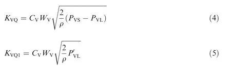
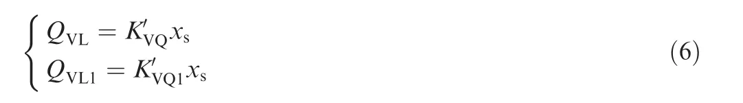
Assuming that the pressure of the pump source with the variable mechanismPVSis a constant,the swashplate variable mechanism could be regarded as an independent hydraulic cylinder system controlled by a load valve.32When the spool displacementxs>0,the flow equation of the servo valve can be described as

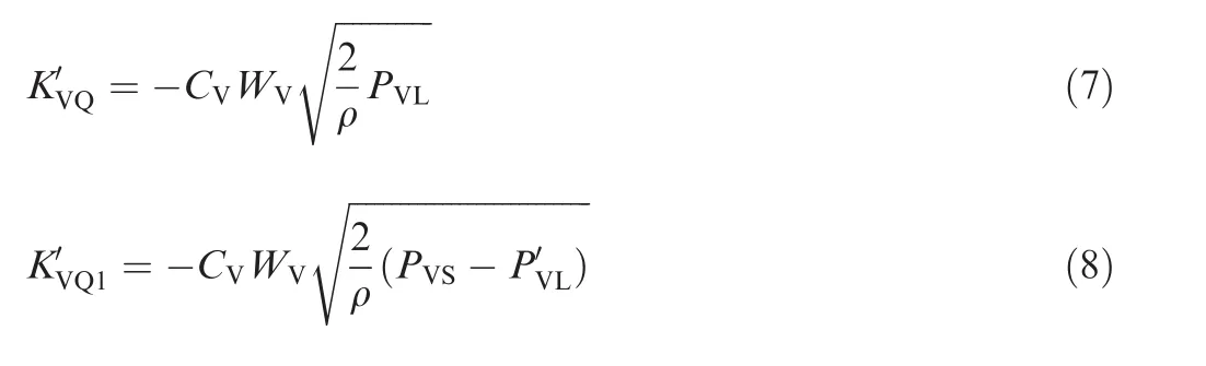
whereQVLis the load flow of the rod cavity within the variable mechanism,andQVL1is the load flow of the non-rod cavity within the variable mechanism.KVQandKVQ1are the flow amplification coefficients in the variable mechanism of the swashplate,which can be described respectively as follows:
When the spool displacementxs<0,the flow equation of the servo valve is shown as
2.1.2.Flow equation of variable cylinder
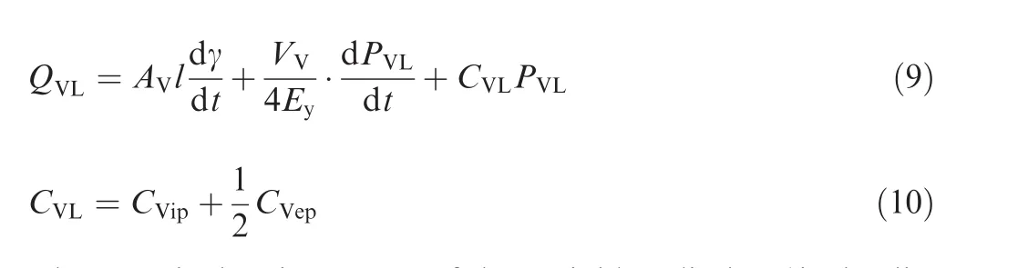
whereAVis the piston area of the variable cylinder,lis the distance between the axis of the cylinder and the rotation center of the swashplate,VVis the total volume of the variable cylinder,Eyis the elastic modulus of the equivalent volume of hydraulic oil,CVLis the total leakage coefficient of the variable cylinder,andCVipandCVepare the internal and external leakage coefficients of the variable cylinder,respectively.
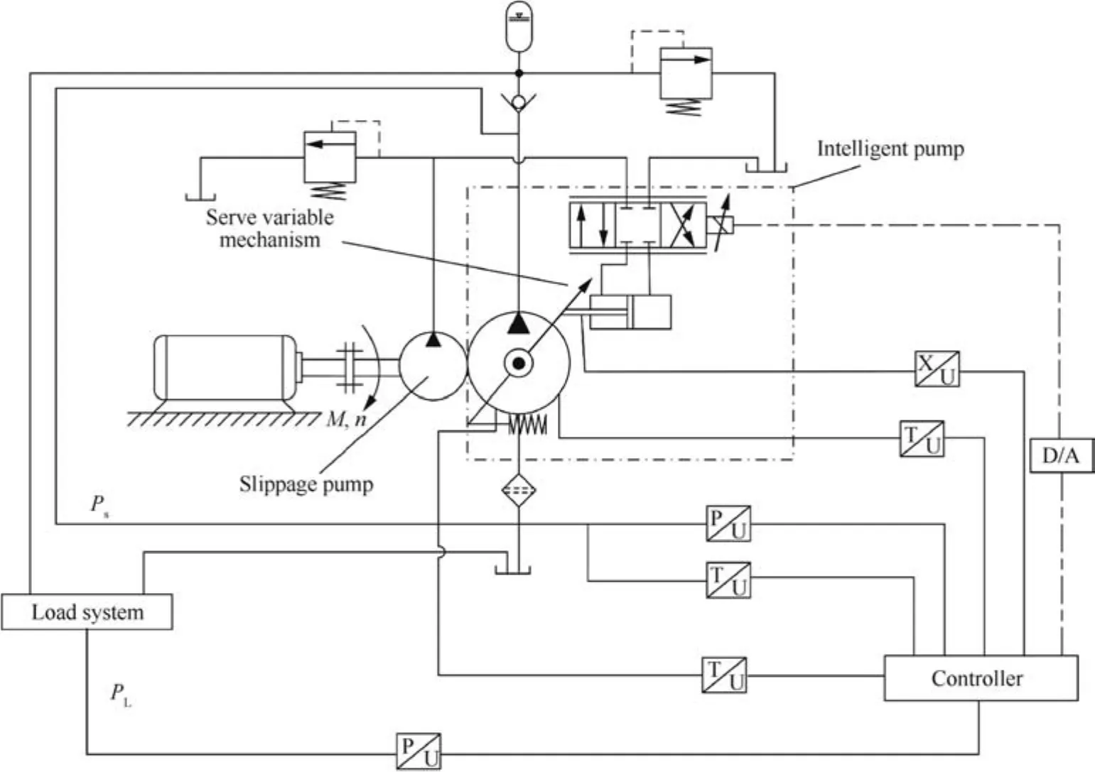
Fig.2 Variable mechanism of intelligent pump.
2.1.3.Torque equation of variable cylinder

whereMLis the output torque of the variable cylinder,MVIis the total inertia torque of the swashplate variable mechanism and the load on the rotary shaft,MVBis the total viscous damping torque of the swashplate variable mechanism,MVKis the elastic torque of the spring,andMLfis the external disturbance torque of the swashplate variable mechanism.Detailed calculations of the above torques can be described as follows:
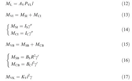
whereMSIandMCIare the inertia torques of the swashplate and the variable cylinder with respect to the rotating shaft of the swashplate,respectively,ISandICare the inertia of the swashplate and the variable cylinder with respect to the rotating shaft of the swashplate,MSBis the viscous damping torque of the swashplate,MCBis the viscous damping torque of the variable cylinder,BSandBCare the viscous damping coefficients of the swashplate and the variable cylinder,respectively,Ris the equivalent radius of the swashplate bearing,andKVis the load elastic stiffness.
Based on the analysis and calculation of each torque,the dynamics of hydraulic servo systems are strongly nonlinear and uncertain,due to fluid compressibility,friction,and aging.Therefore,Eq.(11)can be simplified as follows:
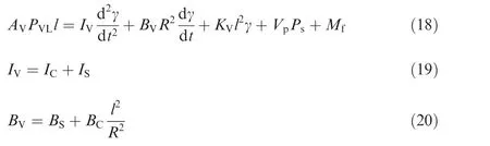
whereIVis the total inertia of the swashplate variable mechanism,BVis the total viscous damping coefficient,Vpis the pressure coefficient of the disturbance torque,andMfis some uncertain torque caused by friction and other disturbances which are nonlinear.
The spool displacementxscan be expressed as follows:

whereKcis the gain of the controller and the sensor,which converts a pressure signal into a displacement signal that can be the output of the servo valve.Puis the control input signal of pressure calculated by the IHPS.
2.1.4.Mathematical model of intelligent pump
The relationship betweenQtand the output pressure of the pumpPscan be shown as

where|QL|is the load flow of the pump,Cplis its total pressure leakage coefficient,andVsis the volume of the output.
According to Eq.(2),(4)and(5),the theoretical flowQtis nonlinear with the angle of the swashplate γ,QVLis nonlinear with the statePVL,which also includes the nonlinear termMfshown in Eq.(18).The nonlinear terms in the system make it more complex,so the traditional transfer function method cannot be used to solve multivariable systems and detect failure situations from inner states.In order to take into account nonlinear factors and observe internal states,the state space method is used to describe the IHPS comprehensively,in which inner states are obtained via an observer.
According to Eqs.(1),(3),(9),(18),and(22),its state space can be expressed as follows:
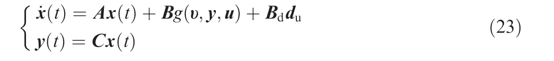
where x(t)∈ R4×1is the state vector,y(t)∈ R2×1is the vector of measurable signals,υ is the vector of measurable signals,u is the control input vector which is assumed to be bounded,and durepresents the unknown input vector.A is the system matrix,B the control matrix,C the output matrix,and Bdthe output matrix,which are matrices with appropriate dimensions.Without losing generality,matrix Bdis assumed to be of full-column rank,whileg(υ,y,u)is the control input function.In the IHPS,the swashplate angle γ and the actual output pressurePscan be obtained by the LVDT and pressure sensors installed on the pump,respectively.An observer can be designed based on the input and signals measured by sensors.
The matrixes with nonlinear parameters,such asg(υ,y,u)andqt(γ),can be obtained as follows:

In order to carry out fault diagnosis of the intelligent pump with a high precision,it is necessary to observe its inner states which are sensitive to typical failures without any knowledge of unknown inputs.
2.2.Main failure modes and influencing factors of IHPS
Previous research has shown that the three main failure modes of an axial piston pump are embodied in leakage,fatigue damage,and aging.18The most important failure mode is the wear of three friction pairs(swashplate and slipper,valve plate and cylinder block,and piston and cylinder bore)33and the bearing and servo of the variable mechanism.When the wear and tear of friction pairs occur time to time,the pump will fail eventually because of leakage.Most of the components in the pump perform rotation and reciprocating motions,and under alternating stress,their fatigue is unnegligible,24such as the fatigue of the spring of the variable mechanism and stress raiser.Aging associated with sealing elements also increases the leakage of the pump.Based on the embedded controller,the failure mode of the IHPS also consists of short circuit,open circuit,and parameter shift.
According to the analysis above,the most important failure effect is the leakage of the intelligent pump.Herein,Cpldenotes the total leakage coefficient of the intelligent pump.The leakage coefficient increases with the failure development of the intelligent pump under cyclic applied loads.KVindicates the elastic stiffness of the variable mechanism of the swashplate,which gradually decreases with an increase of the fault degree of the variable mechanism.
3.Nonlinear unknown input observer(NUIO)design
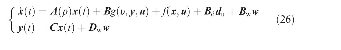
Due to dynamic operational conditions,the signal-based diagnosis method can only be a rough judgment of a failure and some sensors are not sensitive to early failures.The modelbased diagnosis method can be adopted to analyze the change of a dynamic system using deep knowledge.In addition,according to the analysis of the IHPS,nonlinear factors such as the control input functiong(υ,y,u)and the theoretical angular displacementqt(γ)can be obtained through establishing a nonlinear observer.Hence,this paper uses a NUIO to realize the fault diagnosis of the IHPS.Generally,fault diagnosis based on a mathematical model includes two stages:residual error generation and residual error evaluation.There are three methods to estimate a residual error,viz.parameter estimation method,state estimation method,and equivalent space method.A residual error is generated by comparing the measured information of an object to be diagnosed with the prior information of the system expressed by a model.If the residual error is greater than a threshold,the system is considered to be faulty.Since the intelligent pump is very close to an engine,its input or interference might be mixed with unknown factors such as noise and uncertainty.However,the distribution and bound of its input could be specified according to history and prior experience,which leads to the use of the NUIO.Based on the information given by the distribution matrix,the unknown input(interference)can be extracted from the residual error.Because the input and output information required for model-based fault diagnosis is only related to an open-loop system,it is not necessary to consider a controller in the design of a fault diagnosis scheme,which is consistent with the principle of separation of control theory.As long as the input of a regulator is used,it is the same for the fault diagnosis no matter whether the system is in closed or open loop.In order to simplify the model description,the uncertainty of the IHPS is summarized as the additive disturbance term in dynamic nonlinear Eq.(23)in this paper.In order to describe the intelligent pump comprehensively,the mathematical model can be described as follows:

Therefore,the corresponding observer for the IHPS can be designed as


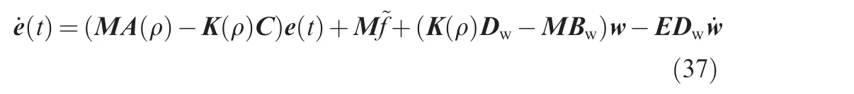
Assuming that the estimation error is e(t)=^x(t)-x(t),its differential equation can be described as
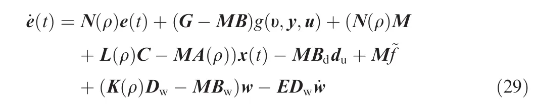

then e(t)goes to zero asymptotically and it is invariant with respect to the unknown input du(t).The notation I indicates the identity matrix.
Eqs.(33)and(34)are equivalent to Eq.(35)as follows:

All possible solutions of Eq.(35)will be

Fig.3 Nonlinear unknown input observer(NUIO)structure.

where Y is an arbitrary compatible matrix and X+= (XTX)-1XT.
The state estimation error will be
If the eigenvalues of Njare stable,then e(t)will approach zero asymptotically,i.e.,^x(t)→ x(t),which means that the observer in Eq.(28)is a NUIO for the IHPS according to the definition of unknown input observer.The design of this NUIO involves solving Eqs.(30)–(34)and guaranteeing that all eigenvalues of the system matrix Njare stable.The necessary and sufficient condition of the existence of a NUIO will be shown as follows26:

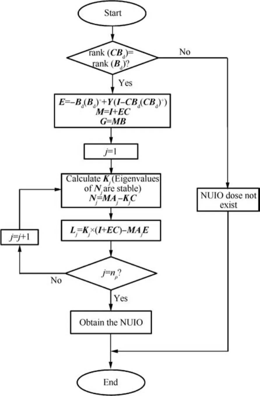
According to the analysis of the NUIO,the key step is to design matrix K(ρ).Once it is available,other parameters of the NUIO can be obtained from Eqs.(30)–(34).The only constraint on K(ρ)is to make the dynamic characteristic matrix N(ρ)stable.Therefore,in the process of calculation,it is necessary to find a suitable value,which leads the state estimation error to zero asymptotically.The flowchart of the process within a specific NUIO is shown in Fig.4.
In the design of a NUIO,the most important part is that,when matrix CBdis full-column rank,matrix N(ρ)could be kept stable by selecting a proper matrix K(ρ).In the IHPS,based on the characteristics of the dynamic system,the poles of matrix N(ρ)are configured to ensure the stability of the observer.
4.Fault diagnosis of IHPS based on NUIO
Based on the NUIO,a simulation model of the IHPS is established by using the Simulink toolbox,and the fault diagnosis system with a residual error is proposed.The simulation parameters of the IHPS are shown in Table 1.
The concrete parameters of the IHPS can be obtained through calculation,and the values of N(ρ),E,L(ρ),and M are as follows:

Fig.4 Flowchart of process of a nonlinear unknown input observer.
where the eigenvalues of each matrix N(ρ)are negative,which satisfies the requirement of the observer system.
Based on the MATLAB platform,a simulation model of the intelligent pump is established,and an observer is designed according to the method in Section 3.Simulation will be carried out for two kinds of typical IHPS faults:one is the leakage of the intelligent pump,and the other is the fatigue damage of the variable mechanism.
When the intelligent pump operates normally,its output pressure varies from 21 MPa to 28 MPa.The input pressure instructions are set according to the pressure requirements under four phases of a flight profile shown in Table 2.The specific output pressure is shown in Fig.5.Obviously,the output pressure of the intelligent pumpPsfollows the command signalPuwell in normal operation.The residual errors of the swashplate angle and the output pressure obtained by the observer are almost equal to zero as shown in Fig.6(a)and(b),which means that the observer can approach a normal intelligent pump.
Suppose that the IHPS is required to track a sine wave signal in the presence of system faults on different severity levels.The tracking trajectories and residual errors of the IHPS,for an input signalPu=(25+sint)×106under a normal condition,are shown in Fig.7.The residual errors of the swashplate angle and output pressure of the IHPS are almost equal to zero,as shown in Fig.8(a)and(b).
In order to verify the fault diagnosis ability of the NUIO,the following failures are injected into the system:
(1)The failure of the variable mechanism(simply expressed as fault I)is injected when the operational time>15 s by adjusting the spring stiffness of the variable mechanism to 50%of its original value.
(2)The leakage failure of the intelligent pump(simply expressed as fault II)is injected when the operational time>15 s through increasing the total leakage coefficientCplto 105%of its original value.
(3)The spring stiffness is adjusted to 50%,25%,10%,or 5%of its original value when the operational time>10 s.
(4)The total leakage coefficient is adjusted to 105%,110%,115%,or 120%of its original value when the operational time>10 s.
The simulation results are shown in Fig.9.
In Fig.9(a)and(b),the residual errors are almost zero before the failure is injected.When the operational time=15 s,fault I is injected and the amplitude of the residual error of the swashplate angle is lower than zero,which means that a decrease of the spring stiffness directly leads to the failure of the variable mechanism.To reach torque balance with the output pressure set by the pressure signals command,the actual swashplate angle should increase with its new spring stiffness,which means that its angle amplitude should be higher than that of the ideal model.Fig.9(b)shows the increase of the residual error of the output pressure in 5 s,which means that the output pressure of the actual intelligent pump is lower than that of the ideal model.The result conforms to the fact that the variable mechanism becomes unable to produce high pressure when a failure happens.It can be said that the residual error is sensitive to fault I and can be used to detect this kind of fault.
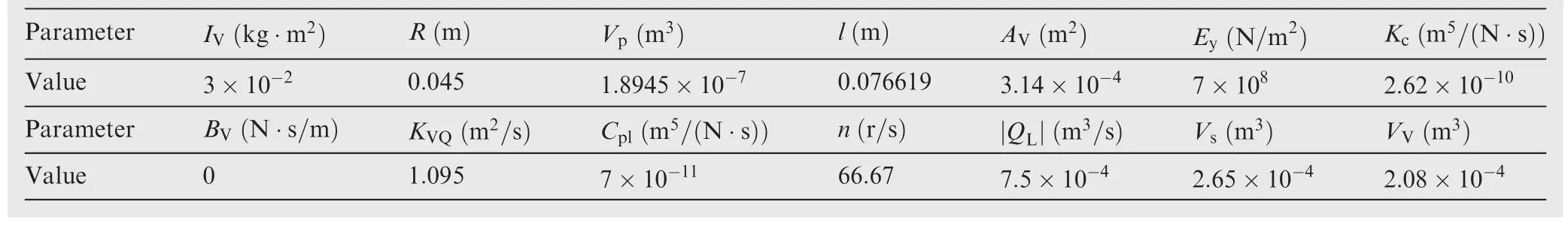
Table 1 Simulation parameters of the IHPS.
In Fig.10(a),when the operational time=15 s,the residual error of the swashplate angle is larger than zero,that is,when fault II occurs,the actual value will be less than the observed one.The reason can be explained that with an increase of leakage in the intelligent pump,the torque used to balance the spring of the variable mechanism decreases.In order to reach a new balance state of torque,the actual value of the swashplate angle will be less than that observed.Meanwhile,as shown in Fig.10(b),the actual value is higher than the observed value,which can be explained as follows:in order to make up for the pressure loss caused by leakage,the actual output pressure should be higher than that calculated by the ideal model.Thus,the residual error of the output pressure is less than zero.As shown in Fig.10(a)and(b),the residual errors can also be used to detect fault II in real time.
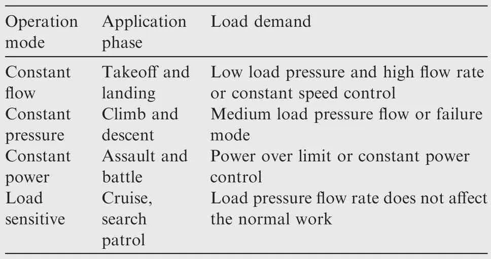
Table 2 Four operation modes of the intelligent pump.

Fig.5 Output pressure Psfollowing the command signal Puin a normal condition.

Fig.6 Residual errors of swashplate angle and output pressure of normal operation.
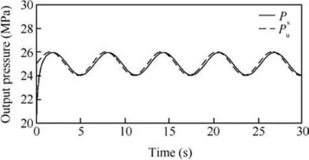
Fig.7 Output pressure Psfollowing the command signal Puin a normal condition(Pu=(25+sin t)×106).
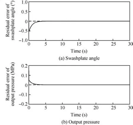
Fig.8 Residual errors of swashplate angle and output pressure of normal operation(Pu=(25+sin t)×106).
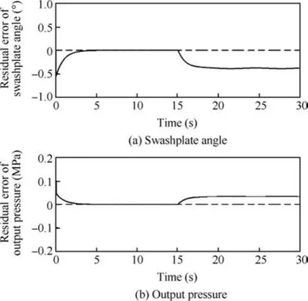
Fig.9 Residual errors of swashplate angle and output pressure of fault I.
This simulation is designed to show the relationship between the severity of fault and the different value of spring stiffness.It is obvious in Fig.11(a)and(b)that the amplitudes of the residual errors of the swashplate angle and output pressure are constantly increasing,which means that,the higher the fault degree is,the greater the values of the residual errors will be.Therefore,the threshold of residual errors can be found via this method.The minimum acceptable level of fault degree can be set according to the simulation results.The threshold can reflect the early failure of the system quickly and its value must be within the range of the sensor’s resolution.The system is considered to be in the state of failure when the residual error exceeds the set threshold.
Similar to the results obtained in simulation(3),as shown in Fig.12(a)and(b),the amplitudes of the residual errors of the swashplate angle and output pressure are constantly increasing respectively,but the directions of the residual errors are different from that of the variable mechanism failure.The more serious leakage failure happens,the greater the residual error values will be in different directions compared to another failure mode.
Therefore,in terms of these two kinds of typical failure mode in the IHPS,the NUIO can accurately detect and isolate a failure.As shown in Fig.13,the failure modes distribute in different regions according to the simulation results,so a simple directional residual error can be used for fault isolation easily.At the same time,the threshold of the residual error can be found through this method.Some strategies can be used to determine the threshold and failure degree with an online method using the NUIO.
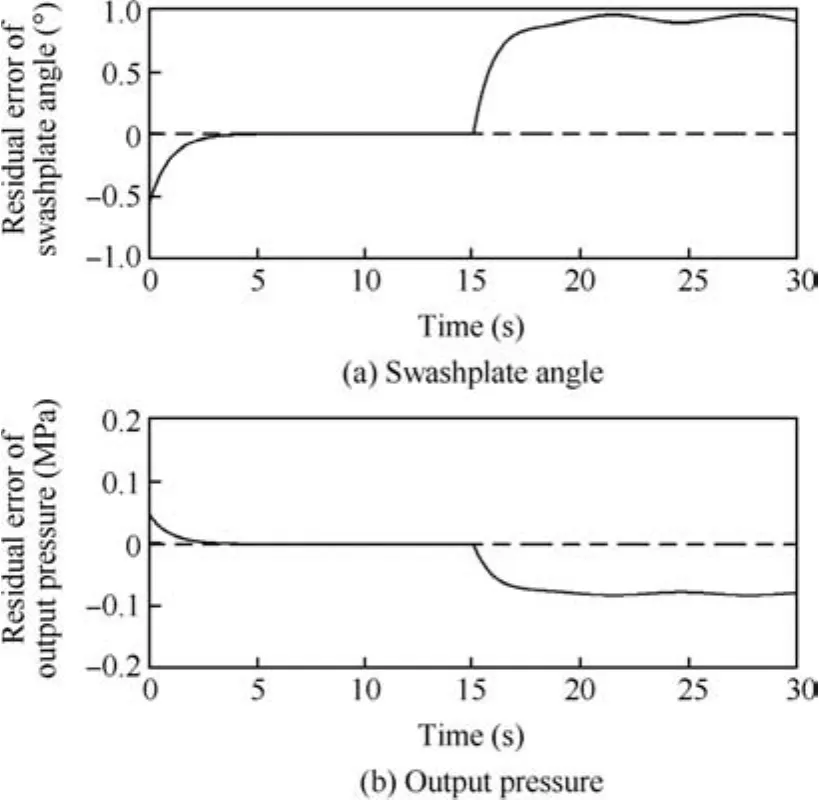
Fig.10 Residual errors of swashplate angle and output pressure in fault II.
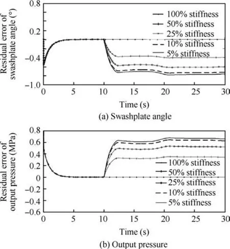
Fig.11 Residual errors of swashplate angle and output pressure in different degrees of fault I.
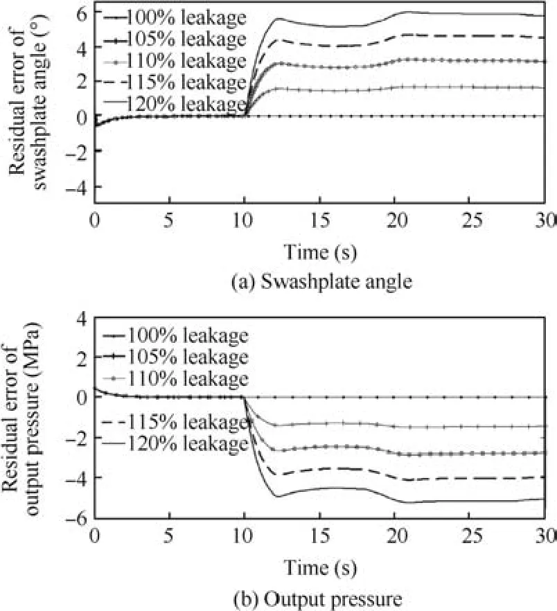
Fig.12 Residual errors of swashplate angle and output pressure in different degree of fault II.

Fig.13 Failure distribution in different degrees of failure.
Through the simulation above,the state observation of the dynamic IHPS is completed with the NUIO.The fault state of the system can be monitored with the residual error signal,and the fault detection of the system can be achieved by setting the threshold of failure in advance.
5.Conclusions
In this paper,model-based fault diagnosis is adopted to diagnose a real-time IHPS.Under an actual flight profile,with the output pressure and swashplate angle signals,the influences of nonlinear factors are taken into account and the dynamic performance is also embodied at the same time.Results show that the residual errors obtained from the NUIO can be used to diagnose the fault within the IHPS.It can be seen that the residual errors of the output pressure and swashplate angle signals could not only diagnose the health status of the IHPS accurately,but also identify the specific type of fault.The method proposed in this paper is an effective fault diagnosis method suitable for real-time systems including the IHPS as well as other hydraulic systems.
Acknowledgements
This study was co-supported by the National Natural Science Foundation of China(Nos.51620105010,51575019 and 51675019),National Basic Research Program of China(No.2014CB046400),and 111 Program of China.
1.Rydberg KE.Energy efficient hydraulic systems and regenerative capabilities,Proceedings of the ninth scandinavian international conference on fluid power;2005 June 1–3;Sweden:Linko¨ping Universitet;2005.
2.Chen B,Wang ZL,Qiu LH.Main developmental trend of aircraft hydraulic systems.Acta Aeronautica et Astronautica Sinica1998;19(7):S1–6[Chinese].
3.Wang ZL,Chen B,Qiu LH.Trends of future aircraft hydraulic system.Hydraul Pnenmatics Seals2000;1:14–8[Chinese].
4.Liu Y,Zuo MJ,Li YF,Huang HZ.Dynamic reliability assessment for multi-state systems utilizing system-level inspection data.IEEE Trans Reliab2015;64(4):1287–99.
5.Wu ZM,Shi QL,Bai PF,Zhong F.Simulation analysis of load sensing system based on amesim.MachToolHydraul2013;44:38–41[Chinese].
6.Mitchell JP.Load sensing hydraulic control system for variable displacement pump.United States patent US 20016216456;2001 Apr 17.
7.Ma JG,Wang SF Wang ZL.Study of intelligent pump scheme.Chin Hydraul Pneumatics2002;11:6–8[Chinese].
8.Zhou RX,Lin TQ,Han JD,Yan DC.Fault diagnosis of airplane hydraulic pump.Proceedings of the 4th world congress on intelligent control and automation.2002 June 10–14;Shanghai,China;2002.
9.Lee JG,Kim OH.Development of a new hydraulic servo cylinder with mechanical feedback.Control Eng Practice1999;7(3):327–34.
10.Wang XJ,Lin SR,Wang SP,He ZM,Zhang C.Remaining useful life prediction based on the wiener process for an aviation axial piston pump.Chin J Aeronaut2016;29(3):779–88.
11.Li YH,Wang ZL.Development of airborne intelligent power supply system.J Beijing Univ Aeronaut Astronaut2004;30(6):493–7[Chinese].
12.Wang SF,Ma JG,Wang ZL.Key technique for the research of airborne intelligent power supply system.Mach Tool Hydraul2003;4:85–7[Chinese].
13.Lu CQ,Wang SP,Zhang C.Fault diagnosis of hydraulic piston pumps based on a two-step emd method and fuzzy c-means clustering.Proc Inst Mech Eng Part C:J Mech Eng Sci2016;230(16):2913–28.
14.Wang JP,Hu HT.Vibration-based fault diagnosis of pump using fuzzy technique.Measurement2006;39(2):176–85.
15.Gao Y,Zhang Q,Kong X.Wavelet–based pressure analysis for hydraulic pump health diagnosis.TransASAE2003;46(4):969–76.
16.Lu C,Ma N,Wang ZP.Fault detection for hydraulic pump based on chaotic parallel rbf network.EURASIP J Adv Signal Process2011;2011(49):1–10.
17.Piao XK.Research about pressure selection of hydraulic system in civil aircraft.Fluid Power Trans Control2011;6:22–4[Chinese].
18.Ma J.Typical failure modes and accelerated lifetime test methods for aircraft hydraulic pump.Chin Hydraul Pneumatics2015;7:1–6[Chinese].
19.Willsky AS.A survey of design methods for failure detection in dynamic systems.Automatica1976;12(6):601–11.
20.Isermann R,Freyermuth B.Process fault diagnosis based on process model knowledge.Adv Inform Process Autom Control1990;31(4):21–34.
21.Isermann R.Fault diagnosis of machines via parameter estimation and knowledge processing—tutorial paper.Automatica1993;29(4):815–35.
22.Liu Y,Lin P,Li YF,Huang HZ.Bayesian reliability and performance assessment for multi-state systems.IEEE Trans Reliab2015;64(1):394–409.
23.Palazzolo JJ,Scheunemann LD,Hartin JR.Leakage fault detection method for axial-piston variable displacement pumps.Proceedings of IEEE aerospace conference;2008 March 1–8;Montana,Big Sky:IEEE;2008.
24.Liu S,Liu X,Han X,Cui X.Fault diagnosis of pump valve spring based on improved singularity analysis.J Vibroeng2014;16(2):704–12.
25.Liu Y,Shi Y,Zhou Q,Xiu R.A sequential sampling strategy to improve the global fidelity of metamodels in multi-level system design.Struct Multidiscip Opt2016;53(6):1–19.
26.Chen J,Patton RJ,Zhang HY.Design of unknown input observers and robust fault detection filters.Int J Control1996;63(1):85–105.
27.Duan GR,Patton RJ.Robust fault detection using luenbergertype unknown input observers-a parametric approach.Int J Syst Sci2001;32(4):533–40.
28.Isermann R,Balle´P.Trends in the application of model-based fault detection and diagnosis of technical processes.Control Eng Practice1997;5(5):709–19.
29.Isermann R.Model base fault detection and diagnosis methods.Proceedings of the american control conference1995 June 21–23;Washington,Seattle:IEEE;2002.
30.Isermann R.Model-based fault-detection and diagnosis–status and applications.Ann Rev Control2005;29(1):71–85.
31.Mileti JA,Lawhead PM.Controlled pressure pumps for more efficient hydraulic systems.SAE technical paper;1986.Report No.:861844.
32.Ma X,Chen B,Gan XH,Sun ZJ.The modeling and simulation of electro-hydraulic proportional valve-controlled cylinder position servo system.Mach Des Manuf2008;4:43–5.
33.Huang XK,Zhang C,Wang SP,Liang XG.An accelerated life test model of hydraulic piston pumps based on dependency analysis:Model development.Proceedings of the 10th industrial electronics and applications(ICIEA)conference;2015 June 15–17;Auckland,New Zealand:IEEE;2015.
杂志排行

CHINESE JOURNAL OF AERONAUTICS的其它文章
- A self-similar solution of a curved shock wave and its time-dependent force variation for a starting flat plate airfoil in supersonic flow
- Robust Navier-Stokes method for predicting unsteady flowfield and aerodynamic characteristics of helicopter rotor
- Effects of trips on the oscillatory flow of an axisymmetric hypersonic inlet with downstream throttle
- Development of a coupled supersonic inlet-fan Navier–Stokes simulation method
- An equilibrium multi-objective optimum design for non-circular clearance hole of disk with discrete variables
- Shock/shock interactions between bodies and wings