Research on vibration suppression of a mistuned blisk by a piezoelectric network
2018-03-21JiuzhouLIULinLIYuFANPengchengDENG
Jiuzhou LIU,Lin LI,Yu FAN,*,Pengcheng DENG
aSchool of Energy and Power Engineering,Beihang University,100083 Beijing,China
bCollaborative Innovation Center for Advanced Aero-Engine,100083 Beijing,China
cBeijing Key Laboratory of Aero-engine Structure and Strength,100083 Beijing,China
dBeijing Institute of Space Launch Technology,100076 Beijing,China
1.Introduction
Bladed disks in aero-engines belong to a class of structures called periodic structures.These structures consist of spatially repetitive substructures which are designed to be identical in ideal situations.1However,in reality,there are always small and random deviations in blade properties,and these are due to factors such as manufacturing tolerance,material inhomogeneity,and in-operation wear.These blade-to-blade discrepancies are called mistuning,which are typically small,but can lead to vibration concentrated in a small region of a structure.This phenomenon is known as vibration response localization.As a result,certain blades can have significantly higher forced response levels than that in an ideally tuned design.For this reason,the phenomenon is also called amplitude magnification.It is considered as one of the major factors inducing High Cycle Fatigue(HCF)of blades.2Therefore,it is important to reduce amplitude magnification induced by mistuning.
Dry-friction damping has been the most common approach in vibration mitigation since a long time ago,while it is not favorable due to the absence of contact interfaces in an integral bladed disk(‘blisk’for short in the rest of the paper)in modern aero-engines.3–6These issues drive researchers to find alternative damping techniques particularly for vibration suppression of a mistuned blisk with low structural damping.In recent decades,piezoelectric materials have received considerable attention because of their properties such as light weight,high bandwidths,efficient energy conversion,and ease of integration.7When embedded in or bonded on fundamental structures,piezoelectric materials can transform mechanical energy to electric energy when they undergo mechanical deformations,and vice versa.Based on this energy conversion capability,various vibration reduction techniques have been developed.Passive piezoelectric damping techniques are initiated by Forward,8who investigated the damping effect of a piezoelectric patch shunted with an inductor.Hagood and Flotow9investigated the possibility of dissipating mechanical energy using piezoelectric shunt circuits containing a resistor and an inductor.They showed that a shunt circuit with a resistor and an inductor performs like a dynamic vibration absorber,especially in cases where the resistor and the inductor are optimally tuned to structural resonance in a manner analogous to a mechanical vibration absorber.The studies of Yun and Kim10and Moheimani11showed that the positions of piezoelectric patches and the reactance of a shunt circuit should be carefully selected to minimize the maximum forced response corresponding to the targeted mode.To overcome the limitation that the value of inductance is too high to be achieved in a low-frequency domain,a synthetic inductance12is used,and an inductance with a value of thousands of Henries has been obtained.13Min et al.14performed a numerical and experimental study for rotating piezoelectric composite subscale fan blades,and they proved that piezoelectric vibration damping could significantly reduce the vibration of composite fan blades in an aero-engine.Zhou et al.15,16proposed a vibration control strategy based on the passive piezoelectric shunt damping technique for a mistuned blisk.Their numerical simulation results indicated that a good performance could be achieved in terms of reducing the vibration of a slowly time-variant mistuned blisk.Then,Mokrani et al.17,18utilized the shape of a targeted mode to organize piezoelectric patches as a modal filter,which decreased the required inductors of a shunted circuit.Their method was firstly validated experimentally on a circular plate,and then applied to a prototype of an industrial bladed drum.
Wang et al.19,20attempted to bond piezoelectric patches on both blades and a disk and then connect them with a network to reduce modal localization of mistuned bladed disks.They showed that the piezoelectric network could create a new electrical energy channel,which could destroy the intrinsic mechanism for vibration localization.Focusing on the vibration suppression of a mistuned bladed disk,Yu and Wang21,22used a negative capacitance to improve the performance of the piezoelectric network.These research efforts offered a start on applying the piezoelectric network to suppress the multiharmonic vibration of a mistuned bladed disk.Liu et al.23considered the non-engine-order excitation from a practical point of view,and the mechanisms of vibration-suppression of a piezoelectric network and a piezoelectric shunt circuit were explained by means of modal analysis and energy analysis.Li et al.24built piezoelectric networks among several identical structures without any mechanical coupling.It was shown through analytical derivation that the response of each component is composed of two parts:one is the response to the excitation acting on that component itself,and the other is the response to the average excitation forces over all the components.Such an additional response can perform as a ‘compensation”to suppress the overall response of a given component.The vibration suppression performances of both Parallel Piezoelectric Networks(PPNs)and Series Piezoelectric Networks(SPNs)have been studied by parameter studies.Results have shown that both PPNs and SPNs can effectively suppress the vibration level,though with different optimal parameters.The best performances for PPNs and SPNs are identical and better than that of passive piezoelectric shunts.The features of PPNs and SPNs were further investigated by considering a more complex yet more realistic situation where the mechanical coupling between adjacent blade sectors was taken into account.25It turned out that the vibration response to nonzero engine-order excitation could be reduced by a PPN,while an SPN only works for zero engine-order excitation.Their analytical and experimental results in their research work26,27indicated that a PPN has an advantage in vibration delocalization of a mistuned periodic structure than a traditional piezoelectric shunt circuit.Meanwhile,only resistors and capacitors have been considered in their research in order to avoid an inductance with a huge value.In these analytical models,piezoelectric patches are all assumed to be located on the surfaces of blades,which would bring an enormous influence to the flow field.Moreover,because the blade surface is usually a complex curved surface,it is difficult to bond or embed a piezoelectric patch on it.It is easier to set piezoelectric patches on the surface of the disk,which,in addition,can minimize the influence to the flow field.When piezoelectric patches are bonded on the disk surface,there will be different dynamic characteristics of the electromechanical system which should be further studied.
When piezoelectric patches are distributed in every sector of a blisk,the electrical period is the same as the mechanical period,and the electromechanical system is a mono-periodic system.Meanwhile,in a case where piezoelectric patches are distributed every few sectors,the electromechanical system becomes a bi-periodic system,which means that the electrical period is different from the mechanical period.This work is meant to contribute to a better understanding of the dynamic characteristics of a blisk with both mono-periodic and biperiodic systems.The aim of the research in the paper is to find an effective alternative damping technique for the mistuned blisks with low structural damping.The content of the paper is organized as follows.First of all,the model of a blisk with a PPN is introduced(Section 2).Then,electromechanical equations are derived based on a lumped parameter model,and a normalizing process is used to make the analytical results more general(Section 3).After the modal analysis of the mono-periodic and bi-periodic electromechanical systems(Section 4),the vibration suppression effect is analyzed,and the impact to the damping effect of the PPN brought by the mechanical coupling between the blades and the disk is investigated(Section 5).Finally,the vibration suppression effect for the mistuned system and the delocalization abilities of the mono-periodic and bi-periodic PPNs are studied using the Monte Carlo analysis(Section 6).
2.Model of a blisk with a PPN
To make better use of the capacity of energy conversion of piezoelectric materials to suppress structural vibration,the most potential and attainable technique may be to embed a piezoelectric patch into a structure or bond it onto the structure surface.In order to minimize the interference to the flow field and make it easy of integration,piezoelectric patches are supposed to be set on the disk or hub surfaces of a blisk in our research as illustrated in Fig.1.In addition,every piezoelectric patch is connected to a shunt circuit which consists of electrical components such as inductors,resistors,and capacitors.Then the shunt circuit is able to dissipate the converted energy into heat,leading to a reduction of vibration.If the shunt circuits in different sectors are connected together,a piezoelectric network is constructed.
A typical lumped parameter model with two Degree of Freedoms(DoFs)in each sector as shown in Fig.2 is used in the research,and this simulated blisk model consists ofNsectors.The parametersmbandkbare the equivalent modal mass and modal stiffness of the blades,respectively.mdandkdare the equivalent modal mass and modal stiffness of the disk sector,respectively.kcdenotes the equivalent modal coupling stiffness which represents the mechanical coupling between adjacent disk sectors.cbandcdrepresent the equivalent modal damping factors of the blades and disk sector,respectively.A piezoelectric patch with a shunt circuit is set on the disk every few sectors,and the voltage difference on a piezoelectric patch is generated by the relative movement in the host structure.For the considered lumped parameter model,the electromechanical coupling effects can be modeled in two ways.One is to add a ‘piezoelectric spring’in parallel with the grounded spring,as in the work of Yu and Wang.22The second idea is to add a ‘piezoelectric spring’in parallel with the coupling spring between adjacent disk DoFs,which can be found in the research works of Zhou et al.15,16Considering the fact that the parameters are given empirically,both ways cannot give an accurate description to a certain blisk,but can only be used as general representations of the blisk.For piezoelectric structures,the featured parameter is the electromechanical coupling factor,so we choose to use the first model and ensure a reasonable coupling factor by setting appropriate model parameters.Connecting all the shunt circuits parallelly as shown in Fig.2,a PPN is constructed.Because the electrical period is different from the mechanical period,the electromechanical system is a bi-periodic system.In this case,the PPN is named as bi-periodic PPN.Assuming that a piezoelectric patch is set everynsectors,we can define the parameterp=N/nas the bi-periodic number,and it should be an integer.Whenn=1(in this condition,p=N),it means that there is a piezoelectric patch in every sector,the electrical period is the same as the mechanical period,and the system is a mono-periodic electromechanical system.In this case,the PPN is named as mono-periodic PPN.
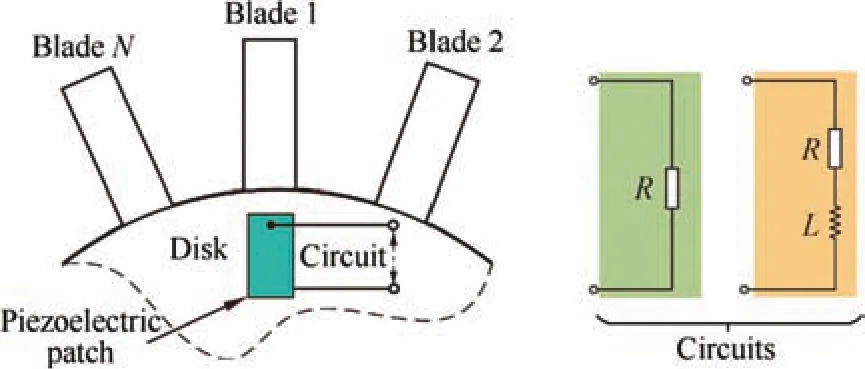
Fig.1 Illustration of a blisk with piezoelectric patches.

Fig.2 Lumped parameter model of a blisk with a Parallel Piezoelectric Network(PPN).
3.Electromechanical equations
When a piezoelectric patch is bonded on the surface of an elastic structure,as illustrated in Fig.3,it works under thed31mode,which is also called the transverse mode.The expansion or contraction of the piezoelectric patch is generated along with the deformation of the supporting structure,and the direction of the expansion or contraction is perpendicular to the electric field.15
The linear piezoelectricity under thed31mode can be represented by the following constitutive equation:

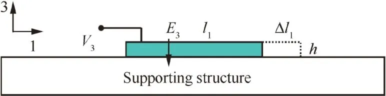
Fig.3 Piezoelectric effect in d31mode.
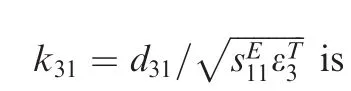
whereD3denotes the electrical displacement(charge/area)in direction 3,E3denotes the electric field in the material(V/m)in direction 3,S1is the material strain in direction 1,andT1is the material stress in direction 1(force/area).εT3represents the permittivity constant measured at constant stress,which relates the electric displacement and the electric field.sE11represents the compliance constant measured in the constant electric field,which relates the strain and stress.d31is the coupling constant,which couples the mechanical and electrical fields through the piezoelectric effect.Both the electric field and the electrical displacement are nearly constant through the thickness direction;therefore,we can introduce a linear relationship for the capacitanceCTpof the piezoelectric patch at a constant stress as follows:


wherexd,jis the displacement of the disk sector with a piezoelectric patch on it,andQjis the electrical charge of sectorj.Combining with the Kirchhoff’s law,we obtain the electromechanical dynamical equations of a single sectorjof the biperiodic electromechanical system as below:

Eq.(2)into Eq.(1),the constitutive equation can be denoted by the charge and electric potential difference as
Assuming that the motion wavelength is much larger than the characteristic dimension of the piezoelectric patch,and the latter is much larger than the thickness of the piezoelectric patch,we can obtain the following relationships:

where Δl1denotes the expansion of the piezoelectric patch in direction 1,ferepresents the force between the piezoelectric patch and the supporting structure in direction 1,andA1is the area of the piezoelectric patch in a sector in direction 1.Substituting Eq.(4)into Eq.(3),the constitutive equation becomes


By substituting Eq.(9)into Eq.(8),we obtain the following non-dimensional equations:
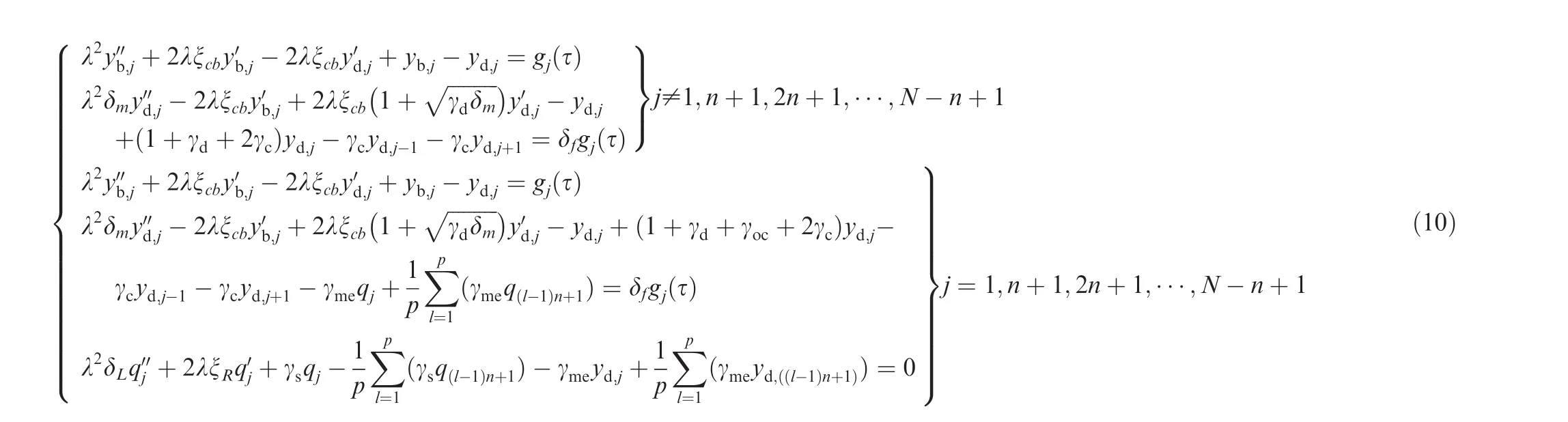
where the prime on a letter means the differentiation with respect to non-dimensional time τ.Hence,we obtain the equation of the blisk withNblades in a matrix form as follows:

in which the vector of the non-dimensional generalized displacement y(τ)has the following forms:

where yj= [yb,j,yd,j]Tis the vector of the non-dimensional generalized displacement of sectorj,and q= [q1,q2,···,qp]Tis the vector of the non-dimensional charge.Matrices M,C,and K are the non-dimensional mass matrix,damping matrix,and stiffness matrix,respectively.
The non-dimensional mass matrix M has the following form:

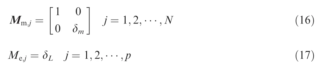
where Mmrepresents the mechanical mass matrix block,and Merepresents the electrical mass matrix block(in the following text,the mechanical matrix block was represented by subscript‘m’,the electrical matrix block by subscript ‘e’,and the electromechanical matric block by subscripts‘me’and ‘em’),which have the following forms:
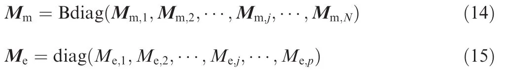
in which Bdiag(·)represents a block diagonal matrix,and diag(·)represents a diagonal matrix.The submatrices have the following forms:
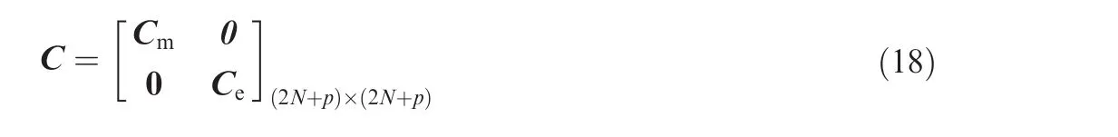
Similar to M,the non-dimensional damping matrix C has the block type of matrices as
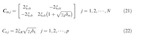
where Cmis the mechanical damping matrix block,and Ceis the electrical damping matrix block.They are denoted by

where the submatrices can be expressed by
The non-dimensional stiffness matrix K has the following forms:
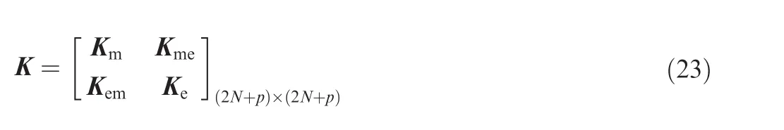
in which Kmis the mechanical stiffness matrix block,and it is denoted by

The submatrices can be expressed by the following formulas:


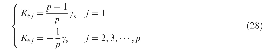
and Kerepresents the electrical stiffness matrix block,which has the following forms:

in which circ(·)represents a circulant matrix,and the elements have the form of
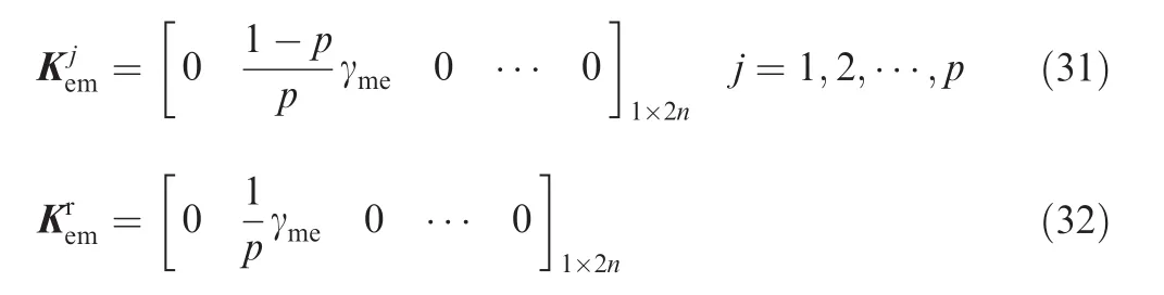
Matrices Kmeand Kemare the electromechanical matrices blocks,and they can be written as
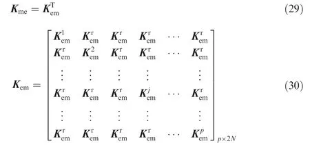
where the submatrices have the following forms:
The non-dimensional force vector has the form of

where gj(τ)= [gb,j(τ),gd,j(τ)]Tis the non-dimensional exciting force vector of sectorj.A rotating blisk in an aero-engine goes through a traveling wave excitation induced by up-stream vanes and the rotation itself.29,30This means that there is a related movement in the circumferential direction between the excitation and the blisk.When observed from a coordinate system fixed on the disk,the excitation is a group of pressure waves traveling in the circumferential direction.Thus,the non-dimensional excitation has the following expression:

where [gb,1(τ),gd,1(τ)]Tis the excitation vector applied to the reference sector.Symbol⊗denotes the Kronecker tensor product,i is the imaginary unit,and θ =2π/Nis the phase difference between adjacent blades.Eq.(34)implies that in each sector,the exciting force has the same magnitude but a different phase.It is usually called engine-order excitation,and parameterEis the excitation order.
4.Modal analysis
The natural modes of the blisk are the homogenous solution of Eq.(11)with damping being neglected as follows:

It leads to an eigenvalue problem as

where Y is the eigenvector,and λ2is the corresponding eigenvalue.In this section,we will discuss the natural characteristics of the blisk with a PPN.
4.1.Blisk with open circuit
The frequency characteristics of the blisk with open circuit is analyzed.In this condition,there is a piezoelectric patch with open circuit in every sector,and a geometry is chosen so that the ratio between parameterkocand the blade stiffness is approximately 5%,16so the calculation is made by taking γoc=0.05γd.The main non-dimensional parameters used are listed in Table 1 unless stated elsewhere.It should be noted that these values are not intended to represent any specific blisk,but to demonstrate the typical characteristics of a common blisk whose blade stiffness and disk stiffness have similar values.
The natural frequencies of the blisk with open circuit are shown as a function of the Nodal Diameter Index(NDI)of blisk modes in Fig.4.Noted that the largest NDI isN/2 if the blade numberNis even,while it is (N-1)/2 ifNis odd.In Fig.4,there are two frequency loci since the lumped parameter model consists of two DoFs per sector.The two loci come close gradually at first and then separate from each other with an increase of the NDI.This phenomenon is known as frequency veering,and the region where the frequency loci are closest is called frequency veering region.The NDI corresponding to the frequency veering region is defined as Veering Nodal Diameter Index(VNDI),and the VNDI is 5 in this model.As explained in Ref.31,the horizontal frequency locus represents blade-dominated modes,while the slope line represents disk-dominated modes.Therefore,before the VNDI,the first-order modal family of the blisk system is disk-dominated,and the second-order modal family is blade-dominated.Meanwhile,it is right the opposite after the VNDI.Therefore,the modal energy of the first-order modal family concentrates on the disk before the VNDI,but that of the second-order modal family concentrates on the blades after the VNDI.This will have a significant impact on the damping effect of the piezo-electric circuit when the piezoelectric patches are set on the disk surface,and it will be discussed in detail in the following section.

Table 1 Values of non-dimensional parameters.
In the investigation on a host structure coupled with a piezoelectric patch connected with a circuit,the generalized electromechanical coupling factor is often used to characterize the coupling level of the system.It is the factor that determines the effect of piezoelectric patches on the structure.The generalized electromechanical coupling factor corresponding to a certain mode can be obtained by32
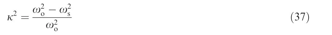
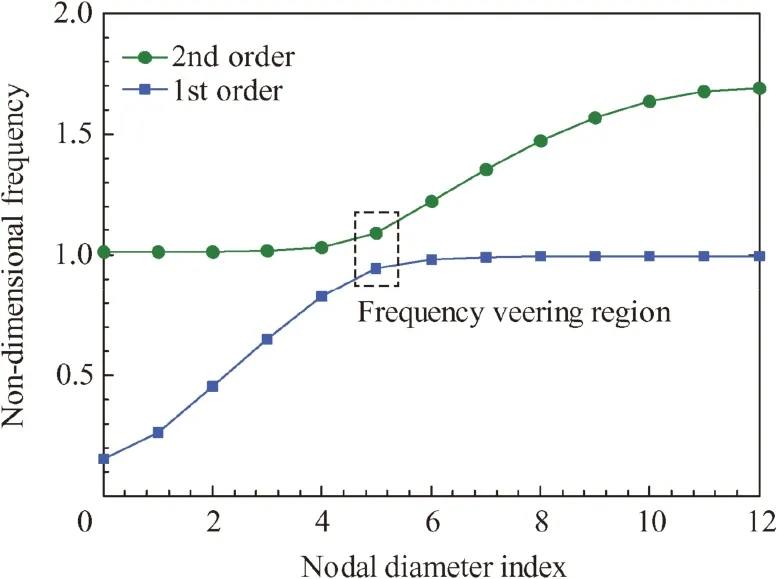
Fig.4 Non-dimensional frequency Nodal Diameter Index(NDI).
where ωois the certain natural frequency of the structure when the circuit is open,and ωsis that when the circuit is short.
In the lumped parameter model used in this study,the parameter that determines the coupling level of the model is γme.In order to obtain a reasonable value of γme,the curve of the relationship between κ2and γmeis drawn corresponding to the first mode of blades when the engine order is 1,in Fig.5.We observe that,with an increase of γme,the generalized electromechanical coupling factor κ2increases.From the curve,the value of γmeis chosen as 0.2 in this study,and the corresponding generalized electromechanical coupling factor is about 0.0114 according to Ref.33.It should be noted that,in this reference,the results are given based on aluminum beams,which may be a significant bias for a blisk.Therefore,the empirical value of the electromechanical coupling factor for the blisk may be obtained by optimizing the geometrical parameters and the distribution of piezoelectric patches based on a high-fidelity finite element model of the blisk.
4.2.Blisk with a PPN
The modes of the mono-periodic electromechanical system are obtained by solving the corresponding eigenvalue problem.The natural frequency distribution of the blisk with an opencircuit shunt and that of the blisk with a mono-periodic PPN are compared in Fig.6.The abscissa is non-dimensional frequency,and the ordinate is a binary notation indicating an existence or no of modal frequencies. ‘1’means ‘Yes’,while‘0’means ‘No’.We observe that for the blisk with an opencircuit shunt,there is a region with a high modal density(region A in Fig.6).This is the region where the frequencies are insensitive to the NDI.Therefore,the modes in this region are blade-dominated modes.For the blisk with a monoperiodic PPN,except for the mechanical natural frequencies,some new circuit frequencies appear and concentrate in region C.The frequencies in region C are the frequencies related to the PPN,and they are insensitive to the NDI.By comparison,it is obtained that the mechanical natural frequencies of the blisk with a mono-periodic PPN are almost the same as those of the blisk with an open-circuit shunt except one in region C,which means that the PPN can affect only the mechanical frequency nearest to the circuit frequency clusters,and the effect is slight(less than 0.5%).
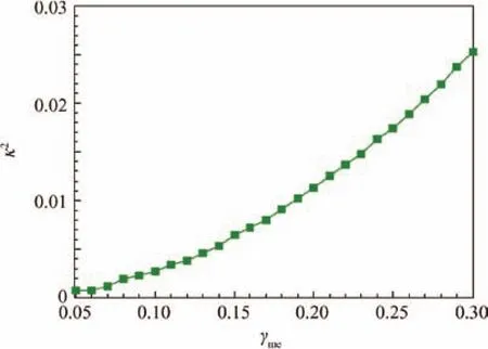
Fig.5 Relationship between γmeand κ2(corresponding to the first mode when E=1).
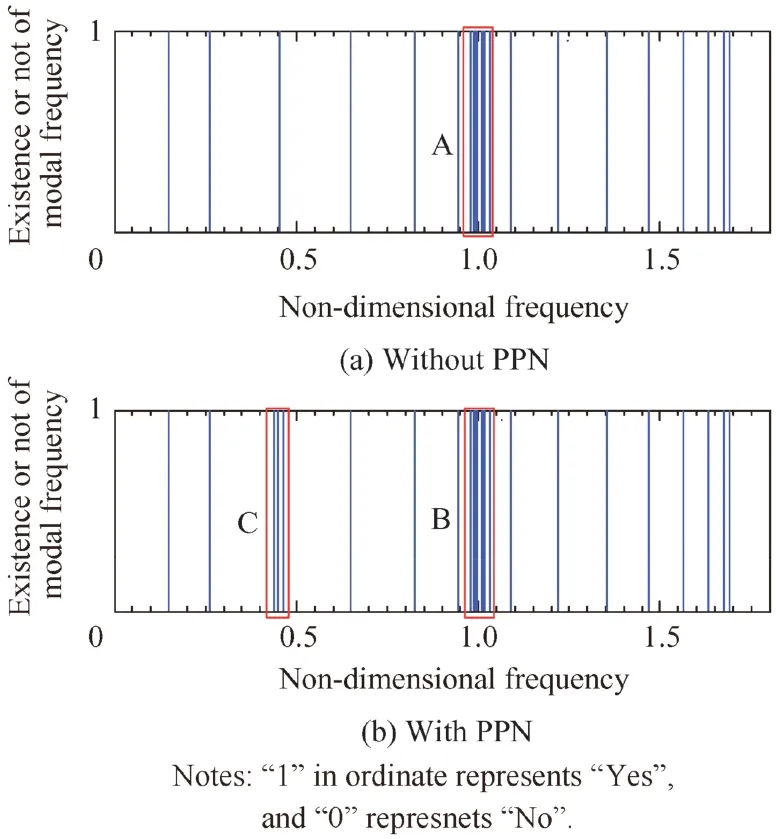
Fig.6 Comparison of natural frequency distribution of mechanical system with and without a PPN.
The nodal diameter spectrum of the mechanical modes of the mono-periodic electromechanical system is shown in Fig.7.We observe that all the mechanical modes of the mono-periodic system contain a single NDI component.The nodal diameter spectra of the bi-periodic systems with different bi-periodic numbers are shown in Fig.8,from which it can be seen that when the mechanical and electrical periods are different,the nodal diameter spectrum of the mechanical modes becomes more complex than that of the mono-periodic system,and it contains more nodal diameter components.The NDI components of the 2nd and 8th modes obtained by the spatial Fourier analysis can be seen in Figs.9(a)and(b),respectively,when the bi-periodic number is 12.From Fig.9,the NDI components of the 2nd mode are 1 and 11,and those of the 8th mode are 4 and 8.Meanwhile,it should be noted that although the nodal diameter spectrum of the mechanical modes becomes more complex,the amplitude corresponding to the new NDI components is much smaller than that of the NDI component corresponding to the mono-periodic system.Moreover,the smaller the bi-periodic number is,the more complicated the nodal diameter spectrum is.The result indicates that although the PPN can only impact the mechanical frequencies slightly,the number of the piezoelectric patches will influence the NDI components of the mechanical modes.

Fig.7 Nodal diameter spectrum of mechanical modes of monoperiodic electromechanical system.
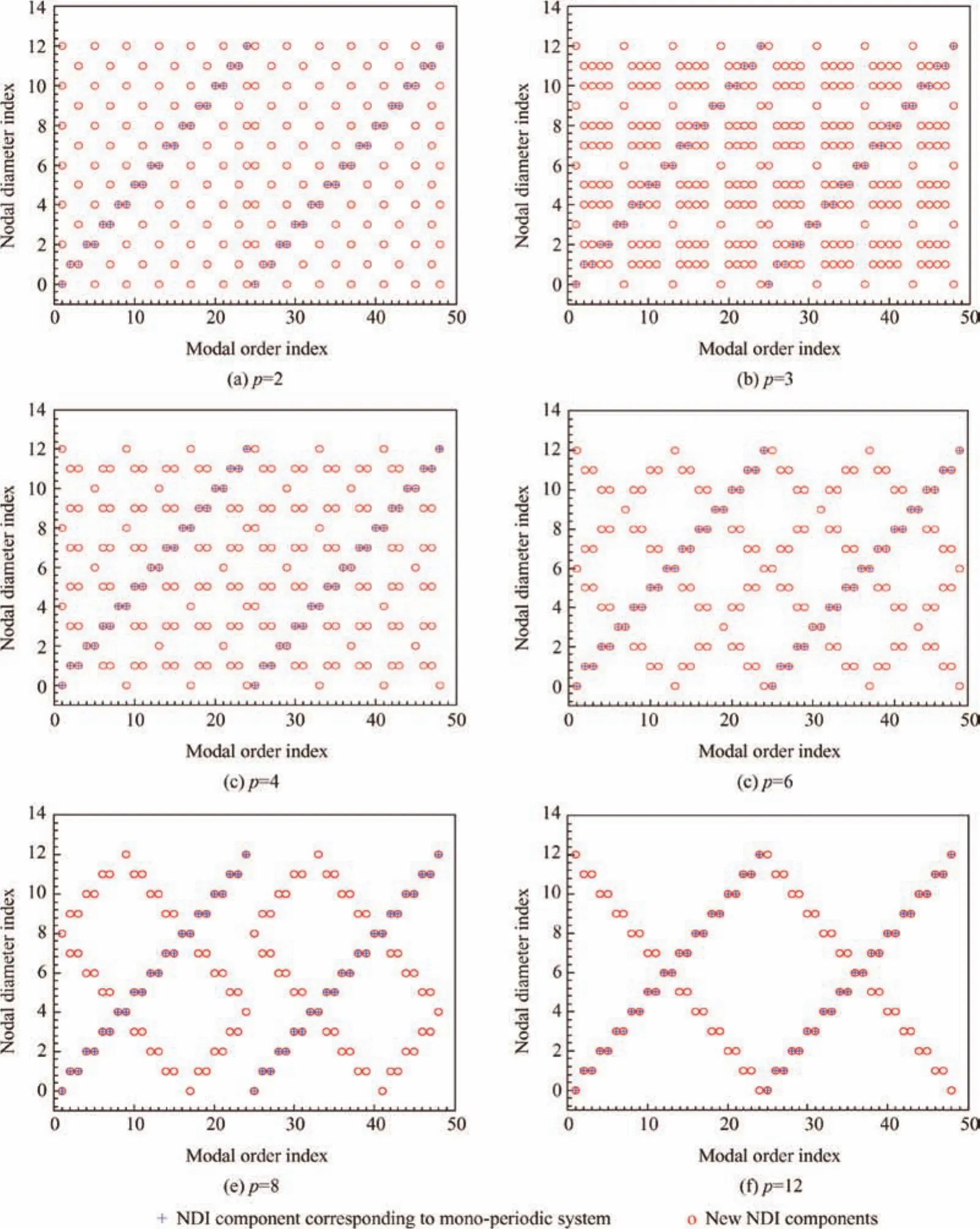
Fig.8 Nodal diameter spectra of mechanical modes of bi-periodic electromechanical systems.
It should be noted that there are some special cases.For example,when the bi-periodic number is 12,the 12th,13th,36th,and 37th modes contain only a single nodal diameter component just as those of the mono-periodic system.This can be explained by analyzing the modal shapes of these modes.The 12th modal shape of the disk is shown in Fig.10(a),in which the disk modal amplitudes of all the sectors with piezoelectric patches are zero.In this case,there is no current in the PPN,and the PPN loses its effect;therefore,it contains a single nodal diameter component.The 13th mode is orthogonal to the 12th mode,and its modal shape is shown in Fig.10(b).The disk modal amplitudes of all the sectors with piezoelectric patches are the same,and there is no current in the PPN either;therefore,it contains a single nodal diameter component.It is the same for the 36th and 37th modes.
5.Forced response analysis and vibration reduction
5.1.Blisk with a mono-periodic PPN
The effect of vibration reduction of the PPN will be investigated in the condition where the electrical parameters in an electric circuit are optimized.Considering the fact that the method of optimization does not influence the result,a numerical method is used here to obtain the optimal electric parameters for the R-PPN and RL-PPN to make sure that all the vibration suppression performances are compared in the optimal condition.One set of the optimal electrical parameters corresponding to an excitation should be calculated specially.For example,whenfb=1,δf=0,and the engine order is 5,the amplitude of the first vibration peak of the blade is shown in Fig.11 by the contour map,where the optimal parameters are obvious and have the following values: δL=1.1175,ξR=0.0125.
The response of the blisk with an R-PPN(there is only one resistor in every sector of the PPN)and that with an RL-PPN(there are both an inductor and a resistor in every sector of the PPN)under different engine-order excitations have been calculated respectively.The ratio of the response to that of the blisk with an open-circuit shunt is taken to evaluate the effect of the PPN.Obviously,the smaller the ratio is,the better the effect of vibration reduction is.The results are shown in Figs.12(a)and(b),respectively,in which the abscissa is the engine-order(from 1 to 12)of the excitation.It can be seen that when the engine order is less than the VNDI(equal to 5 for this analytical model),the suppression effects of both the R-PPN and the RL-PPN to the first resonant response are much better than those to the second resonant response.If the engine-order is larger than the VNDI,the results are inverse.In addition,the RL-PPN has a much better performance than that of the R-PPN in the same condition.The results can be explained through the modal analysis.As mentioned before,the first-order mode family of the considered model is disk-dominated, and the disk has a larger deformation when the engine order is less than the VNDI.Because the piezoelectric patches are set on the disk in the model,the patches have larger deformations and convert more mechanical energy.The result indicates that the mechanical coupling between blades and the disk plays an important role in the damping effect of the piezoelectric circuit when the piezoelectric patches are set on the disk.

Fig.9 NDI components of 2nd and 8th modes.
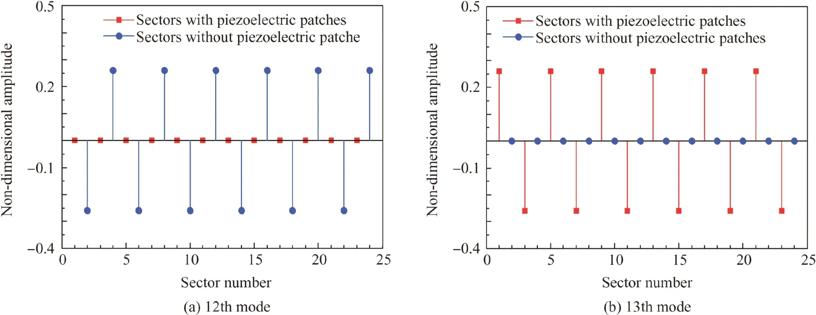
Fig.10 Modal displacement of disk.
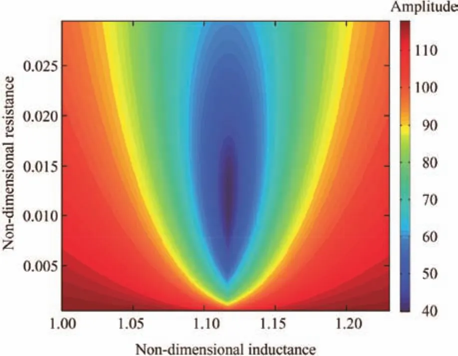
Fig.11 Contour map of forced response of blades to engine order excitation(E=5).
5.2.Blisk with a bi-periodic PPN
When the piezoelectric patches are set only on part of the sectors,the effect of vibration suppression of the system will have a great difference.In Fig.13,the evaluation of the effect of the RL-PPN to the response of blades corresponding to different bi-periodic numbers is shown.From Fig.13,we can see that when the engine order is less than the VNDI(equal to 5 for this considered model),the optimal vibration suppression effect of the RL-PPN to the first resonant response of the blades is effective.It has the best vibration suppression performance when there is a piezoelectric patch in every sector.When there are piezoelectric patches in only part of the sectors,the RLPPN still has a vibration reduction performance,which means that,in reality,we can use an RL-PPN with a small quantity of piezoelectric patches to suppress the vibration of the whole blisk.
Meanwhile,it should be noted that the vibration suppression ability of the PPN is not simply proportional to the piperiodic number((the number of piezoelectric patches).Fig.14 gives the effects of vibration suppression of different bi-periodic electromechanical systems when the engine order is 3.From Fig.14,it can be seen that the PPN with a biperiodic number of 12,8,or 4 has an effective vibration suppression performance to all the blades,but when the biperiodic number is 2,3,or 6,the PPN can only suppress the vibration of the blades effectively in the sectors having piezoelectric patches(indicated by the green squares in Fig.14)or having a π phase difference from the sectors with piezoelectric patches,while in the other sectors,the PPN nearly loses its vibration suppression ability.This phenomenon can be explained through the phase difference between the charges in sectors,which is written as
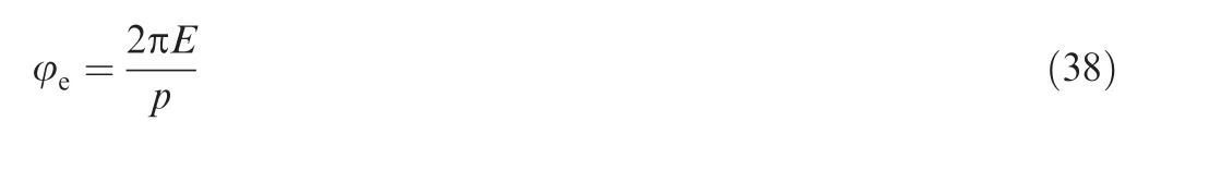

Fig.13 Comparison of vibration suppression effects of biperiodic electromechanical systems.
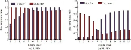
Fig.12 Vibration suppression effect of R-PPN and RL-PPN.

Fig.14 Vibration suppression effect of bi-periodic electromechanical systems under engine-order excitation(E=3).
Obviously,the phase difference φebetween the charges in adjacent electrical sectors is related to the excitation orderEand the bi-periodic numberp.If φeis an integer multiple of π,the charges in different sectors may counterbalance each other,and then the vibration suppression performance of the PPN will decrease significantly.It corresponds to the case where the bi-periodic number is 2,3,or 6 and the corresponding φeis 3π,2π,and π,respectively.Similar cases where the charges counterbalance each other can be found in the following conditions:when the excitation order is 1,the bi-periodic number is 2;when the excitation order is 2,the bi-periodic number is 2 or 4;when the excitation order is 4,the biperiodic number is 2,4,or 8;when the excitation order is 5,the bi-periodic number is 2.In these conditions,the PPN nearly loses its vibration suppression ability as shown in Fig.13.While for a bi-periodic number of 4,8,and 12,the corresponding φeis 3π/2,3π/4,and π/2,respectively.In this condition,although piezoelectric patches are set only in part of sectors of the blisk,the PPN can suppress the vibration of all blades.Therefore,from the analysis above,we can get the conclusion that the vibration suppression performance of the PPN is related to the spatial distribution of the piezoelectric patches on the disk,and the relationship can be illustrated by Eq.(38).Therefore,in practice,we can obtain a good vibra-tion suppression performance of the whole blisk with piezoelectric patches only in part of the sectors by a reasonable design of the spatial distribution of the piezoelectric patches.
6.Mistuned blisk with a PPN
We assume that random mistuning occurs in blades’stiffness,and a non-dimensional mistuning of the blade stiffness is considered.Hence,the non-dimensional dynamic equation of the mistuned blisk with a PPN can be written as

where the mistuning matrix of the blade stiffness ΔK is given as

in which the mechanical mistuning matrix ΔKmhas the following forms:

where the submatrix has the form of
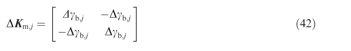
where Δγb,jis the mistuning of blade stiffness in sectorj.
6.1.Mistuned blisk with a mono-periodic PPN
Firstly,the mistuned blisk with a mono-periodic PPN is considered.Plenty of literature has indicated that the vibration amplification due to mistuning is more sensitive near the frequency veering region than elsewhere;therefore,the following research is performed mainly aimed at this region.A random mistuning pattern of the blade stiffness is shown in Fig.15.It follows a normal distribution with a mean value of 0 and a standard deviation of 3%.
The forced response of the system with mistuned blade stiffness distributed as shown in Fig.15 is illustrated in Fig.16 when the system is excited by an engine-order excitation(E=4,fb=1,δf=0).It can be seen that the amplitudes of the forced responses of the blades are different for different sectors,and they are not the same as those in the tuned blisk.Some blades may have significantly larger forced responses than those in the tuned ones,which is known as vibration localization.From Fig.15,both the R-PPN(ξR=0.7410)and the RL-PPN(δL=1.473,ξR=0.023)can reduce the amplitude magnification of the forced response of the mistuned blisk.It should be noted that the electrical parameters used here are the optimal parameters corresponding to the tuned blisk.
However,it seems difficult to draw a conclusion from a single sample of random mistuning.Therefore,for a more meaningful analysis,a Monte Carlo simulation is performed to investigate the statistical characteristics of the mistuned electromechanical system.
The Amplitude Magnification Factor(AMF)is used to measure the amplitude magnification of the mistuned blisk.It is defined as the ratio of the highest vibration amplitude of the blades of a mistuned blisk with an open-circuit shunt or a PPN to that of the corresponding tuned blisk without piezoelectric damping.It can be expressed as
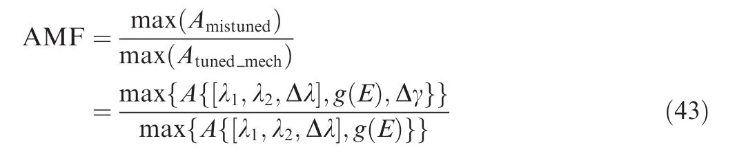

Fig.15 Mistuning pattern of blade stiffness.

Fig.16 Response of mistuned blisk with a PPN.
in which [λ1,λ2]is the sweeping range of the non-dimensional frequency,Δλ is the step size of the non-dimensional frequency which influences the computational precision and speed,andg(E)is a traveling wave excitation.
In the Monte Carlo simulation,the random mistuning follows a normal distribution with a mean value of 0,and its standard deviation is taken from 0%to 20%with an increment of 0.5%.Overall,5000 realizations have been performed corresponding to one standard deviation.
Estimations of the AMF with a 99.9%confidence interval are calculated following a statistical process.The sweeping range is [λ1,λ2]= [0.81,0.84], and the step size is Δλ=0.0005.In Fig.17,the curves of the AMF versus the mistuning strengths of different systems are given.The statistical result of the mistuned blisk with an open-circuit shunt shows that a mistuning of the blisk will lead to an amplitude magnification of the forced response.Fig.18 shows the Probability Density Functions(PDFs)of the AMF(a mistuning strength of 5%)of the system with 3 respective PPNs obtained by 5000 samples.For the mistuned blisk with an open-circuit shunt,the AMF varies from 1.02 to 2.25 with a mean of about 1.43.When the optimal designed mono-periodic R-PPN is introduced into the system,the AMF varies from 0.88 to 2.16 with a mean of about 1.22.Meanwhile,when the mono-periodic RL-PPN is introduced,the AMF varies from 0.11 to 0.35 with a mean of about 0.17.Therefore,from the view of statistical analysis,it can be concluded that both the R-PPN and the RL-PPN with the optimal design parameters can reduce the amplitude magnification of the mistuned blisk,and the RLPPN has a much better performance than that of the RPPN,because it can completely eliminate the amplitude magnification of the forced response of the blisk even in a case with a mistuning of 20%(all AMFs<1).
The distribution of the amplitudes of blades with a mistuning strength of 5%based on 5000 samples is shown in Fig.19(a),from which we can observe the ability of delocalization of the PPN.To illustrate it more clearly,an enlarged image of Fig.19(a)is shown in Fig.19(b)with the abscissa from 2000 to 2200.It can be seen that with the PPN,the amplitudes of blades become more uniform.Especially when the RL-PPN is introduced into the system,the discrepancies of the amplitudes of blades become much less,which means that the PPN can alleviate the vibration localization of the mistuned blisk effectively.
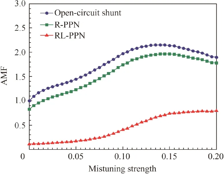
Fig.17 Amplitude Magnification Factor(AMF)vs mistuning strength.
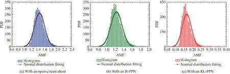
Fig.18 Probability Density Functions(PDFS)of AMF of mistuned blisk.
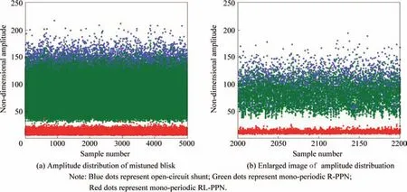
Fig.19 Amplitude distribution of mistuned blisk in Monte Carlo simulation.
The STandard Deviation(STD)of the amplitudes of blades is used to evaluate the ability of delocalization of the PPN,and the smaller the STD is,the better delocalization ability it has.Estimations of the STD of the amplitudes of different blades with a 99.9%confidence interval are calculated following a statistical process with 5000 realizations,and the statistical results with an open-circuit shunt,an R-PPN,and an RLPPN are compared in Fig.20.Synthesizing the results in Figs.16,19 and 20,we can see that both the R-PPN and the RL-PPN have the ability to reduce the discrepancies of the amplitudes of blades in the mistuned blisk,and the RL-PPN can mitigate the vibration localization of the mistuned blisk significantly.
6.2.Mistuned blisk with a bi-periodic PPN
When piezoelectric patches are set only on part of the sectors,the curves of the AMF versus the mistuning strength with different bi-periodic numbers under an engine order excitation(E=4,fb=1,δf=0)are compared in Fig.21.A comparison of the PDF of the AMF with a 5%mistuning strength between different bi-periodic systems is given in Fig.22.From these results,it can be found that when the engine order is 4,the RL-PPN with a bi-periodic number of 12,6,or 3 has an effec- tive ability to reduce the amplification of the response,and when the bi-periodic number is 8,4,or 2,the effect is relatively small.This indicates that when piezoelectric patches are set only on part of the sectors of the blisk,the RL-PPN can still have an effective ability to reduce the amplification of the response(even only 3 patches are used for this model),but the spatial distribution pattern will have large influences to the amplification reduction.

Fig.20 STandard Deviation(STD)of amplitudes of mistuned blisk vs mistuning strength.

Fig.21 AMF vs mistuning strength with different bi-periodic numbers.
7.Conclusions
(1)A PPN can affect only mechanical frequencies near the electrical frequency clusters,and the effect is slight(less than 0.5%for this considered model).In addition,a biperiodic PPN will make the nodal diameter spectrum of the modes more complex,but the amplitude corresponding to the new NDI components is much smaller than that of the NDI component corresponding to the mono-periodic system.
(2)When piezoelectric patches are set on the disk surface,the mechanical coupling between the blades and the disk plays an important role in the damping effect of the PPN,and it should be paid attention to in applications.
(3)The mono-periodic PPN can suppress the amplitude magnification of the forced response induced by the mistuning of a blisk effectively,and it can even eliminate the amplitude magnification even in a case with a mistuning of 20%.Meanwhile,it can mitigate the vibration localization of the mistuned electromechanical system.
(4)If piezoelectric patches are set only on part of the sectors,the bi-periodic PPN still has a vibration suppression ability,but the effect is related to the spatial distribution of the piezoelectric patches on the disk,and the relationship can be represented by Eq.(38)In practice,we can obtain a relatively good vibration suppression performance of the whole blisk by a reasonable design of the spatial distribution of the piezoelectric patches only in part of the sectors.
(5)It should be note that,in reality,a disk is much stiffer than a piezoelectric patch,so geometrical parameters and the distribution of piezoelectric patches should be optimized to insure an acceptable electromechanical coupling factor.Therefore,an important future work is to study the empirical values for the coupling factor based on a high-fidelity finite element model.
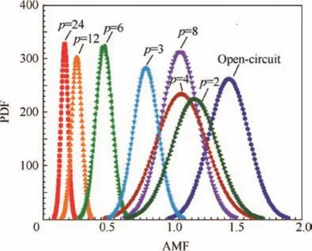
Fig.22 PDF vs AMF of mistuned blisk with different biperiodic numbers.
Acknowledgements
The authors would like to acknowledge the support of the National Natural Science Foundation of China (No.51675022,11702011),and Fan Yu would like to acknowledge the support of China Postdoctoral Science Foundation(No.2017M610741).
1.Castanier MP,Pierre C.Modeling and analysis of mistuned bladed disk vibration:current status and emerging directions.J Propul Power2006;22(2):384–96.
2.Castanier MP,Pierre C.Using intentional mistuning in the design of turbomachinery rotors.AIAA J2002;40(10):2077–86.
3.Grif fin JH.Α review of friction damping of turbine blade vibration.Int J Turbo Jet Eng1990;7(3):297–307.
4.Petrov EP,Ewins DJ.State-of-the-art dynamic analysis for nonlinear gas turbine structures.Proc Inst Mech Eng,Part G:J Aerospace Eng2004;218(3):199–211.
5.Siewert C,Panning L,Wallaschek J.Multiharmonic forced response analysis of a turbine blading coupled by nonlinear contact forces.J Eng Gas Turbines Power2010;132(8):1–9.
6.Herzog A,Krack M,Panning-von SL.Comparison of two widely used frequency-time domain contact models for the vibration simulation of shrouded turbine blades.ASME turbo expo 2014:Turbine technical conference and exposition.2014 Jun 16–20;Dusseldorf,Germany.New York:American Society of Mechanical Engineers;2014:V07BT33A018.
7.Liang J,Liao WH.Piezoelectric energy harvesting and dissipation on structural damping.J Intell Mater Syst Struct2008;20:515–27.
8.Forward RL.Electronic damping of vibrations in optical structures.Appl Opt1979;18(5):690–7.
9.Hagood NW,Flotow AV.Damping of structural vibrations with piezoelectric materials and passive electrical networks.J Sound Vib1991;146(2):243–68.
10.Yun CY,Kim SJ.Optimal design of a piezoelectric passive damper for vibrating plates.Int J Aeronaut Space Sci2006;7(2):42–9.
11.Moheimani SOR.A survey of recent innovations in vibration damping and control using shunted piezoelectric transducers.IEEE Trans Control Syst Technol2003;11(4):482–94.
12.Philbrick Researchers,Inc.Applications manual for computing amplifiers for modeling,measuring,manipulating,and much else.2nd ed.Boston:Inc Nimord Press;1966.p.288–99.
13.Park CH,Inman DJ.Enhanced piezoelectric shunt design.Shock Vib2003;10(2):127–33.
14.Min JB,Duffy KP,Choi BB.Numerical modeling methodology and experimental study for piezoelectric vibration damping control of rotating composite fan blades.Comput Struct2013;128:230–42.
15.Zhou B,Thouverez F,Lenoir D.An adaptive control strategy based on passive piezoelectric shunt techniques applied to mistuned bladed disks.J Comput Appl Math2013;246(1):289–300.
16.Zhou B,Thouverez F,Lenoir D.Vibration reduction of mistuned bladed disks by passive piezoelectric shunt damping techniques.AIAA J2014;52(6):1194–206.
17.Mokrani B,Bastaits R,Horodinca M.Parallel piezoelectric shunt damping of rotationally periodic structures.Adv Mater Sci Eng2015.Available from:https://doi.org/10.1155/2015/162782.
18.Mokrani B.Piezoelectric shunt damping of rotationally periodic structures[dissertation].Brussels:University of Brussels;2015.p.104–18.
19.Tang J,Wang KW.Vibration delocalization of nearly periodic structures using coupled piezoelectric networks.J Vib Acoust2003;125(1):95–108.
20.Yu H,Wang KW,Zhang J.Piezoelectric networking with enhanced electromechanical coupling for vibration delocalization of mistuned periodic structures—Theory and experiment.J Sound Vib2006;295(1):246–65.
21.Yu H,Wang KW.Piezoelectric networks for vibration suppression of mistuned bladed disks.J Vib Acoust2007;129(5):559–66.22.Yu H,Wang KW.Vibration suppression of mistuned coupled blade-disk systems using piezoelectric circuitry network.J Vib Acoust2009;131(2):1–12.
23.Liu J,Li L,Deng P,Li C.A comparative study on the dynamic characteristics of bladed disks with piezoelectric network and piezoelectric shunt circuit.ASME turbo expo 2016:Turbomachinery technical conference and exposition.2016 Jun 13–17;Seoul,Republic of Korea.New York:American Society of Mechanical Engineers;2016:V07AT32A012.
24.Fan Y,Li L.Vibration dissipation characteristics of symmetrical piezoelectric networks with passive branches.ASME turbo expo 2012:Turbine technical conference and exposition.2012 Jun 11–15;Copenhagen,Denmark.New York:American Society of Mechanical Engineers;2012.p.1263–73.
25.Li L,Deng P,Fan Y.Dynamic characteristics of a cyclic-periodic structure with a piezoelectric network.Chin J Aeronaut2015;28(5):1426–37.
26.Deng P,Li L,Li C.Study on vibration of mistuned bladed disk with bi-periodic piezoelectric network.Proc Inst Mech Eng,Part G:J Aerospace Eng2016;231(1):350–63.
27.Li L,Deng P,Liu J.Theoretical study of the vibration suppression on a mistuned bladed disk using a bi-periodic piezoelectric network.Int J Turbo&Jet-Eng2016;https://doi.org/10.1515/tjj-2016-0028.
28.Fan Y.Multi-scale approaches for the vibration and energy flow through piezoelectric waveguides:simulation strategies,control mechanisms and circuits optimization[dissertation].Lyon:Ecole Centrale de Lyon;2016.p.20–2.
29.Figaschewsky F,Giersch T,Kuhhorn A.Forced response prediction of an axial turbine rotor with regard to aerodynamically mistuned excitation.ASME turbo expo 2014:Turbine technical conference and exposition.2014 Jun 16–20;Dusseldorf,Germany.New York:American Society of Mechanical Engineers;2014:V07BT35A013.
30.Martel C,Corral R.Asymptotic description of maximum mistuning amplification of bladed disk forced response.J Eng Gas Turbines Power2009;131(2):1–10.
31.Kenyon JA,Grif fin JH,Kim NE.Sensitivity of tuned bladed disk response to frequency veering.J Eng Gas Turbines Power2005;127(4):835–42.
32.Preumont A.Dynamics of electromechanical and piezoelectric systems.Netherlands:Springer;2006.p.99–105.
33.Ducarne J,Thomas O,DeuJF.Placement and dimension optimization of shunted piezoelectric patches for vibration reduction.J Sound Vib2012;331(14):3286–303.
杂志排行

CHINESE JOURNAL OF AERONAUTICS的其它文章
- A self-similar solution of a curved shock wave and its time-dependent force variation for a starting flat plate airfoil in supersonic flow
- Robust Navier-Stokes method for predicting unsteady flowfield and aerodynamic characteristics of helicopter rotor
- Effects of trips on the oscillatory flow of an axisymmetric hypersonic inlet with downstream throttle
- Development of a coupled supersonic inlet-fan Navier–Stokes simulation method
- An equilibrium multi-objective optimum design for non-circular clearance hole of disk with discrete variables
- Shock/shock interactions between bodies and wings