Bionic Quadruped Robot Dynamic Gait Control Strategy Based on Twenty Degrees of Freedom
2018-01-26DaweiGongPengWangShuangyuZhaoLiDuandYuDuan
DaweiGong,Peng Wang,Shuangyu Zhao,Li Du,and Yu Duan
I.INTRODUCTION
M ORE and more researchers have been giving great attention to the robot research[1].Quadruped robot which can be used to simulate the common animals becomes a hot topic in recent time[2].It has higher carrying capacity and stability compared with single-legged and biped robot.And it also reduces redundancy in structure design compared to hexapod and more legs robot.So the quadruped robot has been studied widely and developed rapidly in the recent years.Quadruped robot is inspired by four-legged animals not only in structure but also in the ways of moving.The common gaits include craw l,trot,pace,bound and so on.In which,craw l is static gait,and others are dynamic gaits.Static gait is the most stable gait in quadruped movement.But dynamicgait has more advantages on speed and efficiency that makes it become a hot topic for research[3].
Nowadays,scholars have obtained some achievements in quadruped robot research.In 2004,Hornbyet al.realized pace gait and trot gait in a straight line on Sony’s two small quadruped robot ERS-110 and OPEN-R using evolutionary algorithm.Both of them have three degrees of freedom in leg,two in hip and one in knee[4].In 2011,Wanget al.realized bound gait in a simple quadruped robot which has four passive legs and a spine connecting front and rear body[5].Each hip is equipped with only one drive.Quadruped robot models used in the above researches are simplified in leg structure and degrees of freedom compared to tetrapods.Due to this reason,this model-based control algorithms have few limitations to complex road.In 2008,Maet al.proved that quadruped robot is able to achieve bound gait under the initial condition of a fixed point by numerical calculation[6].However,this conclusion has not been realized in simulation platform.
In summary,the paper presents a complex quadruped robot model with 20 degrees of freedom which could contain all the above models.Each leg in the model has 5 degrees of freedom,a yaw and a pitching freedom of hip,a pitching freedom of knee and ankle.And each leg also has an elastic component simulating leg tendon in motion as a passive degree of freedom.The model retains basic motion characteristics of quadruped leg movement that can simulate four-legged animals movement very well.Finally,we realize a better pace gait and bound gait in the ADAMS-MATLAB simulation platform that is proving the feasibility of technical route.Although the technical route making pace gait and bound gait is an example,it also applies to dynamic gait such as trot gait.The research of trot gait is so mature that it is not being focused on in this paper.
In the current research,scholars focus more on flexible contact and gait control of single-legged robot.But,it lacks attention of the effect on high speed contact,with feet and ground,in quadruped robot dynamic gait.And we also ignore how to achieve stabilizing control.Due to this reason,we build a relatively complete 3D model for quadruped robot based on SLIP model,analyze the inverse kinematics of the model,plan the trajectory of the dynamic gait with 0 velocity and acceleration when touch the ground and analyze the hydraulic drive.At last,we achieve a better simulation of pace gait and bound gait.The paper is focusing on the dynamic gaits control in such a complex situation for the first time.This can provide reference for quadruped robot design.
II.SLIPMODEL
Spring loaded inverted pendulum(SLIP)is a very common model in research of biological running and jumping,with few degrees of freedom,simple structure,less coupling and simple control,as shown in Fig.1[7].The motion of planar SLIP model can be decomposed into the forward direction(Xdirection)and the vertical direction(Ydirection).Its motion has the standing and vacating phase.Running or jumping could be considered as alternation between two states.The 3D-SLIP model also has speed in lateral direction(Ydirection)except in forward direction(Xdirection)and vertical direction(Zdirection).Compared to the planar SLIP model,it is a more appropriate choice for bionic robot research.
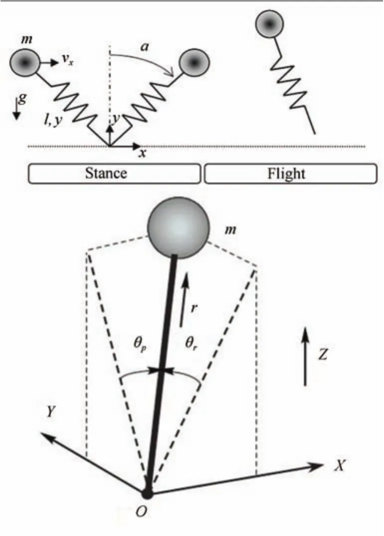
Fig.1.Planar SLIP model and 3D-SLIP model.
A.SLIP-based Single-leg Robot Control Algorithm
Single-legged robot control algorithm is the basis of legged robot control which includes forward speed,body attitude and jumping height control[8]−[10].
B.Quadruped Robot Modeling
Quadruped robot model from this paper is based on 3DSLIP.The 3D-model is provided by the Harbin Institute of Technology,as shown in Fig.2.
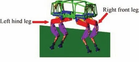
Fig.2.Quadruped robot’s 3D model.
III.PATH PLANNING FOR QUADRUPED ROBOT DYNAM IC GAIT
A.Gait Description
The gait is a coordinative relationship of animals limb between time and space.It includes regularly repeating sequence and method of moving legs.
Quadruped robot gait can be divided into static and dynamic gait.Static gait means projection of robot gravity on the ground is always located within the supporting triangle.It has the slowest speed and the best stability.Crawl is a kind of static gait.Common dynamic gait includes trot,pace,bound and gallop,in which,gallop is a symmetric gait with time difference of any two legs movement.The other three are symmetrical gaits.
Trot gait means that the two legs on diagonal have consistently movement.And they are as standing and vacating legs by turns.
Pace gait means same-side feet having synchronous motion.The body during exercise has significantly tumbling motion which causes less stability.But it avoids the mutual interference between front and rear legs like trot.So,it is more suitable for camels,giraffes and other long leg quadrupeds.
Bound gait means front and rear legs are paired respectively.It suits for smaller flexible quadruped with poor walking ability.The body has an obvious pitching during motion.
In this paper,we focus on control strategy of symmetrical gait based on pace and bound gait.
B.Virtual Leg
Virtual leg is an important tool in research of multi-legged robot,proposed by Sutherland in 1989.The virtual leg means one virtual leg could instead of two real legs when the two real legs are exerting equal force on the ground,producing same horizontal displacement and equal torque on the hips.Different quadruped robot gaits can be equivalent to the corresponding biped robot gait by the principle of virtual leg,as shown in Fig.3.

Fig.3.Application of the virtual leg in quadruped robot.
And biped robot motion can be seen as two single-leg robots movement whose each leg could as standing and vacating leg by turns.So,we can establish connections between quadruped robot and single-leg robot by virtual leg to extend of control strategy from single-leg robot to quadruped robot.
C.Foot Trajectory Settings
During the forward movement,the trajectory of the swing foot needs to satisfy some conditions.
1)Leg lifting must be enough high to prevent collision with ground and obstacles.
2)Velocity and acceleration of the swing foot are set to 0 to reduce the impact of collision with ground when starting and hitting the ground.
Using the simple curve(such as sine curve,elliptic curves)as the swinging foot trajectory curve,the foot will have an additional acceleration at the moment it touching ground.So we consider using composite cycloid instead of simple curve in this paper.
First,consider the robot forward foot trajectory.
According to the condition 2),the acceleration is set to 0 when getting off and hitting the ground.The acceleration curve can be set to a sine curve.

The velocity is also 0when leaving and touching the ground.Integral the formula att=0 ort=T,˙x=0.The following equation will be obtained:

By the velocity curve,we can obtain foot trajectory curve as follows:

Boundary conditions are as follows:

Substitute this into(3),we have:

Therefore,we can obtain:

Sis the robot step length.
Then,focus on the robot foot trajectory in the vertical direction.
Swinging leg movement in the vertical direction is symmetric about the highest point.So only consider the case 0≤t≤T/2.
The velocity and acceleration of swinging leg in the vertical direction are both 0 at start of movement in every cycle and at the highest point.So,we can describe vertical foot trajectory as sine curve learning from forward acceleration curve.We have:

When,we can obtain:

Boundary conditions are as follows:

The foot trajectory curve in the vertical direction is as follows:

His the height of the swing leg lift in the vertical direction.
It is easy to validate the foot trajectory curve in the vertical direction also satisfying the formula in the second half of the cycle.
If we setT=0.7 s,step lengthS=450mm and foot left heightH=100mm.
Fig.4 shows the swinging foot trajectory based on composite cycloid planning.Thex-axis represents the forward direction.Andz-axis represents the vertical direction.And Figs.5 and 6 are displacement time series plots of forward and vertical direction.The first and second derivatives of the curve are both 0 at the start and the end that matches the foot trajectory condition correctly.
D.Inverse Kinematic Analysis of Quadruped Robot Leg
Kinematic analysis is the basis for robot path planning.We establish the relationship between the trajectory of foot and the joint angle through it.And we could implement the expected foot motion by controlling the joint angle[11],[12].
Structure of the single leg is shown in Fig.7,where ΣNis global coordinate system;ΣBis moving coordinate system at the center of the body.H,M,K,E,Frepresent yaw motion,pitching motion of hip joint,knee,ankle and foot,respectively.The lengths of the leg between joints are,in order,l0,l1,l2,l3.θ1represents Yaw angle of hip.Angles of leg areθi=(θi1,θi2,θi3).Yaw,Pitch,Roll are namedα,β,γ.
The rotation matrix from ΣBto ΣNis

Assume the position ofBandFare known as(xb,yb,zb)and(xf,yf,zf).In theXB-YBplane,the angle between foot andXBisϕ.It is not difficult to get the conclusion according to mechanism sketch

Substituting each vector into the equation,inverse kinematics solution can be obtained as follows:

Fig.4.The foot trajectory curve.
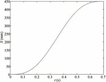
Fig.5.Displacement time series plots in forward direction.

Fig.6.Displacement time series plots in vertical direction.
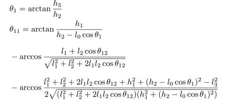

Fig.7.Model of frame and structure of the single leg.

where

dandware the length and width of the body.
In the same way,we can obtain inverse kinematics solution of other 3 legs.In the case of foot trajectory is known,corresponding joint angles can be calculated by inverse kinematics.
E.Analysis the Hydraulic Drive System
Quadruped robot model used in this paper is driven by hydraulic cylinders.We can control the hydraulic position to achieve the control of robot leg joints[13].
Each leg has four hydraulic cylinders for driving in this model.The first one drives yawing motion of the hip.The second one drives pitching motion of the hip.The third one drives knee pitching movement.And the fourth one drives ankle pitching motion.
First,calculate the first hydraulic cylinder elongation.We intends to use cosine law to calculate the corresponding angle which hydraulic cylinder in.It can be calculated by cosine law through calculating the corresponding angle in the triangle which includes hydraulic cylinder.
According to Fig.8,it is easy to obtain:

According to the relation between each angle in graph,we have:

So


Fig.8.Hydraulic cylinder of the first joint.
This is the extended length of first hydraulic cylinder.Minusing original length,we can get hydraulic cylinder’s elongation.
Fig.9 shows hydraulic cylinder of the second,third and fourth joints.From Fig.9,it is easy to obtain:

According to the cosine law,we have:


Fig.9.Hydraulic cylinder of the second,third and fourth joints.
This is the extended length of second,third and fourth hydraulic cylinder.Their elongations are respectively equal to the result of extended length minus original length.
F.Planning of State Variables
The above analysis can fully describe the motion of the robot’s single leg.The quadruped robot gait can be planned based on it.The implementation process of quadruped robot gait is actually the coordination process of four legs movement along established path.In the control process,it is often useful to define the movement in one stage as a state variable.By controlling the state variable,the robot could move along the established path.
In the example of pace and bound gait,we define the state variable for every process of paired legs rise and fall.It can be expressed as Fig.10.
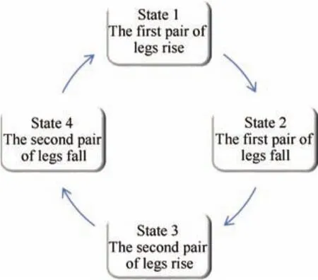
Fig.10. Transition between the state variables.
In this paper,the left front leg and left hind leg are the first pair of legs in pace gait.The right front leg and right hind leg are the second pair.In bound gait,the left front leg and right front leg are the first pair of legs.And the right hind leg and left hind leg are for the second pair.Four-leg support state is the initial state of every cycle.Cycles of four states form the forward gait.
IV.SIMULATION RESULTS AND ANALYSIS OF GAIT
According to the above method,joint angles of each leg can be figured out by foot trajectory.Then,the hydraulic cylinder elongation as driving function can be obtained.Attitude angles(yaw,pitch,roll)are adjusted by PID control based on SLIP.Import the 3D-model of quadruped robot into Adams and establish control variables and constraints.Adopting the ADAMS and MATLAB joint simulation method,we can obtain simulation graphics and parameters of robot motion in ADAMS post-processing module.
A.Result of Pace Gait
As shown in Fig.9,we begin from the state of four leg on land.Then robot first raises left front leg and left hind leg simultaneously.Then,the left front and left hind legs touch the ground,and raise right front leg and right hind leg up.It fits in with the characteristics of pace,reciprocating cycle.(Fig.11 is in right view.The actual forward direction in simulation of the robot is in left in Fig.11.So that the right front and right hind leg in this right view is actually left front and left hind leg of the robot,and vice versa).
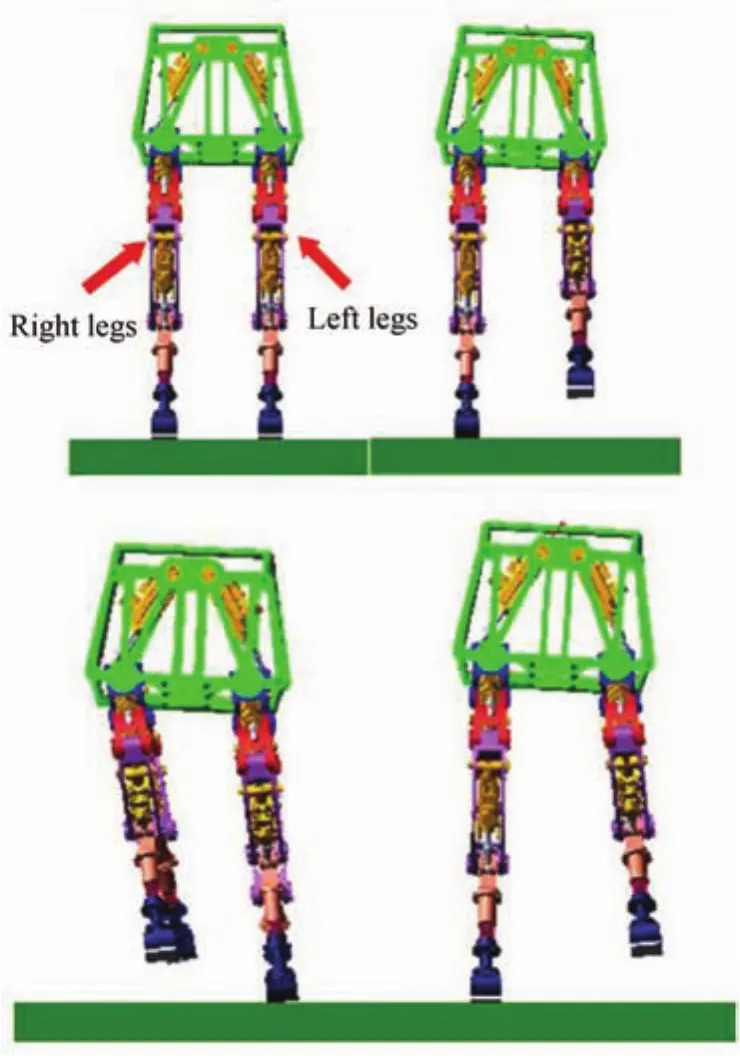
Fig.11. Four-leg state of pace gait.
As Fig.12 shows,at the beginning of the movement,the body’s pitch,roll and yaw have greater volatility.And then the movement becomes smooth.

Fig.12. Curve of attitude angle in pace gait.
B.Result of Bound Gait
Similar as Fig.11,Bound Gait can be seen in Fig.13.As seen in Fig.14,the body pitch and roll is better in convergence.However,due to control error,the yaw fluctuated slightly with periodical change as same as the single-leg robot movement.
V.CONCLUSION
1)Using composite cycloid to plan the swing foot trajectory curve makes the velocity and acceleration to be 0 which can reduce the impact of collision with ground and energy loss.
2)After setting the swing foot trajectory curve,we can get relationship between trajectory and joint angle by inverse kinematic analysis for single leg model of quadruped robot.This is the foundation of control for single leg motion.
3)Establishing the relationship between the joint angle and the hydraulic cylinder elongation by analysing of hydraulic cylinder strobe,then we can adjust the joint angle through control of hydraulic cylinder elongation.
4)By combining with the pace and bound gait characteristics,we can plan state variables and achieve two gaits cyclical motion.
5)Based on the above analysis,we realize a better pace and bound gait of quadruped robot in simulation platform proving the feasibility of technical route.

Fig.13. Four-leg state of bound gait.
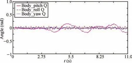
Fig.14. Curve of attitude angle in bound gait.
[1]W.He,Y.T.Dong,and C.Y.Sun,“Adaptive neural impedance control of a robotic manipulator with input saturation,”IEEE Trans.Syst.Man Cybern.Syst.,vol.46,no.3,pp.334−344,Mar.2016.
[2]Z.Y.Liu,D.D.Liu,and T.L.Shi,“Gait planning and movement simulation of biped robots,”J.Wuyi Univ.(Nat.Sci.Ed.),vol.30,no.1,pp.29−33,Mar.2016.
[3]Z.W.Chen,B.Jin,S.Q.Zhu,H.L.Huang,and G.Chen,“Design and experiment of single leg of hydraulically actuated bionic multi-legged robot,”Trans.Chinese Soc.Agric.Eng.,vol.32,no.5,pp.36−42,Mar.2016.
[4]G.S.Hornby,S.Takamura,T.Yamamoto,and M.Fujita,“Autonomous evolution of dynamic gaits with two quadruped robots,”IEEE Trans.Robot.,vol.21,no.3,pp.402−410,Jun.2005.
[5]X.Wang,M.T.Li,P.F.Wang,and L.N.Sun,“Running and turning control of a quadruped robot with compliant legs in bounding gait,”inProc.2011 IEEE Int.Conf.Robotics and Automation,Shanghai,China,2011,pp.511−518.
[6]S.P.Ma,G.H.Miao,and L.Q.Yu,“Research on the leaping gait of four feet robot with articulated legs,”J.Machine Des.,vol.25,no.8,pp.32−36,Oct.2008.
[7]B.B.Xu,Y.J.Li,and Z.Wang,“Control method of spring loaded inverted pendulum model for legged robots,”Mech.Eng.Automat.,no.4,pp.141−143,Aug.2014.
[8]M.T.Li,Z.Y.Jiang,W.Guo,and L.M.Sun,“Leg prototype of a bioinspired quadruped robot,”Robot,vol.36,no.1,pp.21−28,Jan.2014.
[9]M.Raibert,M.Chepponis,and H.Brown,“Running on four legs as though they were one,”IEEE J.Robot.Automat.,vol.2,no.2,pp.70−82,Jun.1986.
[10]M.H.Raibert,H.B.Brown Jr,and C.Michael,“Experiments in balance with a3D one-legged hopping machine,”Int.J.Robot.Res.,vol.3,no.2,pp.75−92,Jun.1984.
[11]G.B.Xu and L.Z.Zeng,“Robot and it’s simulation,”Comput.Simulat.,vol.33,no.2,pp.1−16,May2016.
[12]J.H.Zheng,J.C.Niu,M.S.Jiang,M.Li,and X.W.Rong,“Dynamic analysis and simulation of spring legs in quadruped robot based on trot gait,”J.Cent.South Univ.(Sci.Technol.),vol.46,no.8,pp.2877−2883,Aug.2015.
[13]M.Zhuang,Z.W.Yu,D.P.Gong,M.L.Xu,and Z.D.Dai,“Gait planning and simulation of quadruped robot with hydraulic drive based on ADAMS,”Mach.Des.Manufact.,no.7,pp.100−102,Jul.2012.
杂志排行
IEEE/CAA Journal of Automatica Sinica的其它文章
- Encoding-Decoding-Based Control and Filtering of Networked Systems:Insights,Developments and Opportunities
- Internet of Vehicles in Big Data Era
- Residential Energy Scheduling for Variable Weather Solar Energy Based on AdaptiveDynamic Programming
- From Mind to Products:Towards Social Manufacturing and Service
- Analysis of Autopilot Disengagements Occurring During Autonomous Vehicle Testing
- A Methodology for Reliability of WSN Based on Software De fined Network in Adaptive Industrial Environment
