A Novel Robust Attitude Control for Quadrotor Aircraft Subject to Actuator Faults and Wind Gusts
2018-01-26YuyingGuoBinJiangandYouminZhang
Yuying Guo,Bin Jiang,and Youm in Zhang,
I.INTRODUCTION
RECENT scientific innovations and improvements have boosted the utilization of unmanned aerial vehicles(UAVs)in a large and expanding number of applications such as law enforcement[1],marine operations[2],battle damage assessment[3],agriculture services[4],mapping and photographing[5],wild fire surveillance[6],[7],inspection of buildings and bridges[8],surveillance over nuclear reactors[9]and power lines[10].Due to the requirements of autonomous flight under different flight conditions without a pilot onboard,control of UAV flight is much more challenging compared with manned aerial vehicles since all operations have to be carried out by the automated guidance,navigation and control(GNC)algorithms embedded on the onboard flight microcomputer/microcontroller or with limited interference by a ground pilot if needed.Moreover,during all these missions,the precise attitude control combined with w ind gusts attenuation capabilities and the enhanced reliability and safety of complex and autonomous systems due to occurrence of faults are necessarily required.So,an effective yet easy to implement controller,which has the capability of ensuring its effectiveness even in the presence of actuator faults and strong disturbances,is required.
For the quadrotor helicopter,as an example of UAV systems,which is relatively a simple,affordable and easy to fly system,the accurate attitude control of it in harsh environmental conditions due to w ind disturbances is an open challenge.Particularly,robustness issues can be critical for the rotorcrafts due to the complicated aerodynamic effects(which make it difficult to obtain an accurate dynamic model),such as the errors from sensors(like measurement noises)and external disturbances(like winds).Many researches have addressed the design of proper attitude control strategies for quadrotor.Nevertheless,only a few studies about robust control of aircraft in the presence of wind can be found in the literature.In[11],a back stepping-based controller with input saturations for the hovering flight of a UAV was introduced and it was applied(in simulation)to an airship UAV in face of w ind disturbances.The problem of UAV path planning with w ind disturbances is discussed in[12],[13].In[14],a novel nonlinear feedback control law is developed to compensate for modeling errors which can perform robustly against external perturbations such as wind gusts.Reference[15]and[16]account for wind gust disturbances,but only as linear perturbations.The quadrotor is a 6 degree-of-freedom(DOF)device with only four actuators,which makes it an under-actuated vehicle with unstable dynamics and highly coupled states.Moreover,due to load limitations,there is no hardware redundancy,so the enhanced reliability and safety of a quadrotor in the presence of faults is critical.Then,the development of an autonomous fault diagnosis[17]and recovery system[18]−[21]that can cope with these faults is necessarily needed.In[22],an adaptive PID controller is proposed for fault tolerant control of a quadrotor helicopter system in the presence of actuator faults,and a fuzzy logic controller is used to tune PID gains online where the tracking error and the change of the tracking error are used to determine control parameters.However,PID controllers are reliable with certain level of robustness to model uncertainties and disturbances.Moreover,when the control input is a step signal,the output of system cannot be step due to the inertia of the system,and there will be large initial error.Model predictive control(MPC)is a promising tool for fault tolerant control applications[23]due to its prominent capabilities such as constraint handling,flexibility to changes in the process dynamics and applicability to nonlinear dynamics.However,MPC needs an almost explicit model of the system to calculate a stabilizing control signal,meanwhile,the abrupt changes in the model parameters,due to failure,cannot be predicted beforehand and an online data-driven parameter estimation methodology is required.Sliding mode control(SMC)and back stepping techniques have also been used in[24]and[25],and in these works the convergence of the quadrotor internal states is guaranteed;however,the computations required are relatively excessive.
Given that the quadrotor is an under-actuated system,the possible set of available solutions for control and fault recovery is rather limited.Moreover,in realworld applications there are always measurement noises and w ind gusts.Also,to the best of authors’know ledge,there are no fault recovery methods based on active disturbance rejection control(ADRC)presented for a quadrotor aircraft in literature,therefore,the main objective of this paper is to develop fault tolerant control methods that are effective,simple to implement and robust to model uncertainties and external disturbances for quadrotor control system in the presence of actuator faults,w ind gusts and measurement noises by ADRC initiated by Han[26].In contrast to previous methods,the developed fault tolerant control method is a remarkable control strategy for four reasons:1)it is a robust control strategy,where the model of quadrotor is extended with a new state variable,which includes all unknown dynamics and disturbances that are left unnoticed in the normal plant description and is online estimated using a state observer called extended state observer(ESO);2)the online estimation of the new state is used to separate the system and the gentle disturbances,which in turn indirectly simplifies the model to a large extent,and the real time compensation of the uncertainty also reduces the trouble in its modelling;3)discrepancies in modelling will not affect the control mechanism,as this technique involves inclusion of all uncertainties as the extended state variable;4)robustness and uncertainty reduction ability of this method makes it an interesting solution in scenarios where the full know ledge of the system is not available.
The construction of this paper is organized as follows:In Section II,a nonlinear dynamic model with actuator faults and w ind gusts is derived.The fault tolerant method based on ADRC is developed in Section III.To analyze the performance of the developed fault tolerant controller,several simulations are carried out and presented in Section IV.Conclusions and future work are finally discussed in Section V.
II.QUADROTOR’S MATHEMATICAL MODEL SUBJECT TO ACTUATOR FAULTS AND W IND GUSTS
A.Preliminaries
A quadrotor aircraft is actuated by four rotors.The coordinate systems and free body diagram for the quadrotor are shown in Fig.1.There are two reference frames subjected to the quadrotor:The earth-fixed frameE=(OE,xE,yE,zE)and the body-fixed frameB=(OB,xB,yB,zB).It is assumed that the body-fixed frame and the center of gravity of the quadrotor must coincide.A cross formed by two arms holds the four rotors,two rotors at the two ends of one arm rotate in the clockwise direction,while the other pair of rotors rotates in the opposite direction to cancel the yawing moment.To describe the behavior of the quadrotor,its absolute position vector is denoted asξ=[x,y,z]T∈Eand attitudinal vector is denoted as Euler anglesη=[φ,θ,ψ]T∈E.Euler angles are respectively roll angleφ,pitch angleθ,and yaw angleψwith the assumption ofThe linear motions along withx,y,zaxes and rotating motion around thez-axis are accomplished by changing the speed of rotors properly.Control forces and moments are generated by varying the speed of the rotors(Ω1,Ω2,Ω3,Ω4)as shown in Table I.In Table I,a(+)symbol indicates that increasing the corresponding rotor speed generates a positive force/moment,while a(−)symbol indicates that decreasing the corresponding rotor speed generates a positive force/moment.To get fromEtoB,we first rotate aboutzEaxis by the yaw angle,ψ,then rotate about the intermediateyEaxis by the pitch angle,θ,and finally rotate about thexEaxis by the roll angle,φ.The rotation matrix for transform ing the coordinates fromEtoBis given by
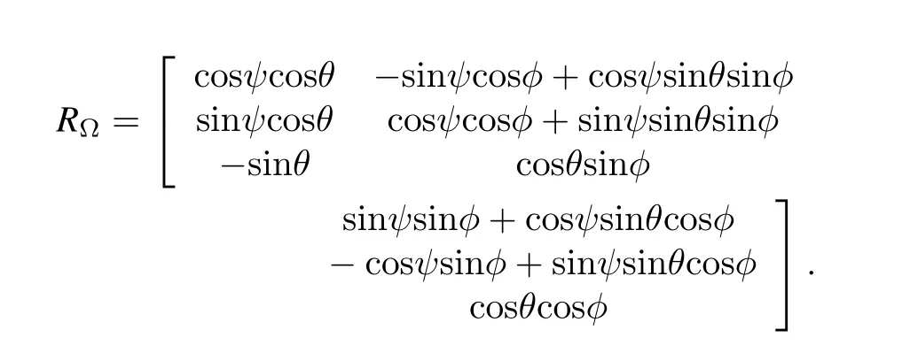
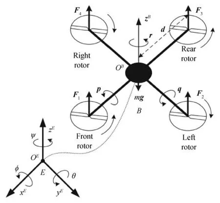
Fig.1.Quadrotor model.
By using the New ton-Euler approach,the general mathematical model describing the dynamics of an aircraft evolving in a three-dimensional space is expressed in(1)[27],

TABLE I VARIATION OF ROTOR SPEEDS TO GENERATE CONTROL FORCES AND MOMENTS

whereνis the generalized velocity vector with respect toE-frame and Ω is the angular velocity expressed inB-frame,ˆΩ denotes the anti-symmetric matrix of Ω,mis the mass of the rigid body,Jdenotes the constant inertia matrix around the center of mass,F∈R3is non-conservative forces expressed in an inertia frameE,andτ∈R3is torques applied to its center of mass and specified with respect to the body frameB.Ω×[0 0JrΩr]denotes the gyroscopic effects produced by the propeller rotation,Jris the total rotational moment of inertia around the propeller axis and Ωris the overall propellers’speed which is defined in(2),

B.Wind Gusts Modeling
In realworld applications,a quadrotor is generally exposed to crosswind.A crosswind is defined as thew ind which occurs perpendicular to the vehicle but parallel to the ground,i.e.,the quadrotor is disturbed by lateral w ind.If an aircraft is experiencing a crosswind,it will be pushed over or yawed away from the w ind.Consequently,this leads to additional forces,fWi,acting over each rotor(see Fig.2).These forces are due to the airflow generated by the lateral wind.It means that the magnitude of these forces is a function of the incoming later alairflow coming from thew ind.Under the crosswind,the total thrust,can be expressed as follows[28]:

whereρis the air density andAis the propeller area,fMi=is the translational force produced by rotori,andbis the thrust coefficient.Vpis the induced w ind speed in the main propeller andis the total induced w ind speed by the rotor and lateral windVw,and this is given by

whereαis the angle between the rotor axis and the lateral w ind axis,and when the w ind is coming from the right in thex-axis,α=90o.It is important to notice that,without lateral w ind,Vw=0,then this givesˆV=Vp,fWi=0 andfTi=fM i.
Moreover,the motor torque is opposed by an aerodynamic drag,τdrag.For definition,the aerodynamic drag is given byThus,the aerodynamic drag could be considered likewherekdrag>0 is a constant depending on the density of air,the radius,shape of the blade and other factors.When the quadrotor is perturbed by the crosswind,the induced forcesfWiin each rotor produce aerodynamical wind torques in the rotorcraft,and these moments could be expressed byis the distance between the center of the quadrotor and the centre of a propeller.
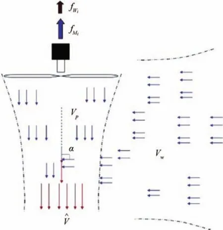
Fig.2.Analysis of the main and lateral thrusts.
On the other hand,the gravitational force applied to the vehicle is,wheredenotes the unit vector codirectional with thezE-axis,andgrefers to the gravity acceleration.Therefore,one has

withand
Consequently,(1)is rewritten as follows:

Thus,developing(5)and(6),it follows that

whereis the perturbed vector induced by w ind,and it is defined as follows:
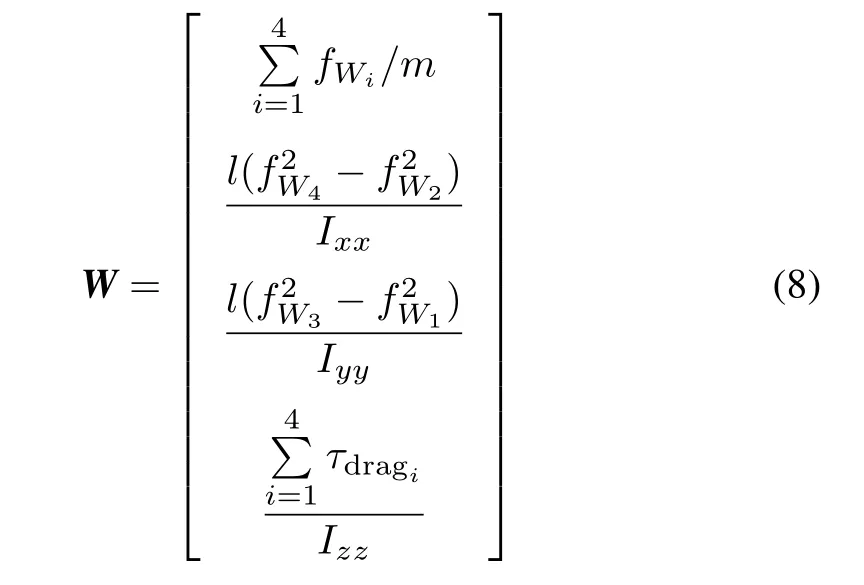
whereIxx,IyyandIzzdenote the inertia moments in the body fixed frame,and the propellers’speed inputs are given through(9),

wherebanddare the thrust and the drag factors,respectively.U1denotes the normalized total lift force,andU2,U3andU4correspond to the control inputs of the roll,the pitch and the yaw moments,respectively.Then,rearranging the(9)in a matrix form

whereU=[U1U2U3U4]Tis the movement vector andFM=[fM1fM2fM3fM4]Tis the thrust vector withfMi=bΩ2i,i=1,2,3,4.The constant matrixLis defined according to

C.Actuator Dynamic Model With Loss of Effectiveness(LOE)Fault
The rotors are driven by DC motors,and with the assumption that the thrust dynamics for all the actuators are identical,and from,one has

The nonlinear and linearized dynamic equations of the propeller angular speed Ωiand the thrustFMaround an operating pointF0are provided in[19]and[29],and interested readers can refer to the two references for details.So,for the sake of brevity,the paper presents the linearized dynamic equation of the input voltageuto the thrustFMin(13)

whereA,BandCare constant matrices andu=[u1u2u3u4]Tis defined as the vector of the input voltages to the propellers.
Considering(10)and(13),the following equation is obtained

where[1 1 1 1]T,and the parametersA t,BtandCtare the linearized coefficients.
The LOE fault is characterized by a decrease in the actuator gain from its nominal value.In case of a LOE fault,the speed of the quadrotor deviates from the commanded output that is desired by the controller.In other words,one instead has

where Ωirefers to the actual output from theith actuator and Ωciis the commanded output by the controller andkairepresents the LOE fault gain.Therefore,the resulting thrust force from this actuator changes according to the(16)

Then,one has

Therefore the dynamics ofFMdefined in(13)would also change due to the LOE fault,so(14)can be rewritten as follows:

whereandare coefficient matrices.
Remark 1:In this paper,it is assumed that the only coefficients subject to change due to a fault areA0,B0,while the coefficientC0would remain unaffected.If the actuators have the same parameters,in other words,A ti=AtandBti=Btfori=1,2,3,4,then the system is healthy,otherwise an actuator fault occurs.
Remark 2:It should be noted that if the actuators do not have the same characteristics,it is necessary to derive the dynamic equations of the movement vector,then the thrust dynamics for all the actuators are not identical since the dynamic equations of the movement vectorUchange.
III.ROBUST NONLINEAR RECOVERY CONTROLLER DESIGN
Although ADRC inherits from proportional–integral–derivative(PID)control,it has unique qualities that makes it such a success.These unique qualities are:the error-driven,rather than model-based,control law;it offers the best state observer;it embraces the power of nonlinear feedback and puts it to full use;it is a useful digital control technology developed out of an experimental platform rooted in computer simulations.The normal ADRC consists of a tracking differentiator(TD),an extended state observer(ESO)and a nonlinear state error feedback(NLSEF).However,in the realworld,there are always measurement noises in control systems.Motivated by this fact,an improved ADRC control strategy is developed in this section.That is,using nonlinear function fal(·)given in(24)to filter out the measurement noises.The improved ESO can not only estimate states of plant and overall disturbances,but also efficiently filter out measurement noises in systems.
Equation(7)is recalled and rewritten as follows:

wherefi(·)andW idenote the internal dynamics disturbance(such as modeling errors)and the external disturbance(i.e.,w ind gust),i=1,2,3,4,respectively.2=1/Ixx,b3=1/Iyy,b4=1/Izz.
The control strategy design,for example the roll control,is developed as follows.For the roll control,considering the second order system as follows:

whereor simply denoted asf,represents both the internal dynamics and the external disturbance,vydenotes measurement noises,xis system state,and for the roll control,one has

whereφdis desired values.
A.Tracking-differentiator(TD)
In the transition design,both the transition signalv1and its derivativev2are simultaneously given.A nonlinear TD was constructed based on the fact that the numerical integration provides more stable and accurate results than numerical differentiation in the presence of noises.
Considering the roll control for the design,a second-order TD can be designed as follows:

wherev=φdis the expected output,v1is the tracking ofv,andv2is the derivative ofv1.Tis the sampling period,andrandhare adjusted accordingly as filter coefficients.The function fst(·)is defined as follows:

with

B.Improved extended-state-observer(ESO)with fal(·)filter
To suppress the measurement noises,an improved ESO with fal(·)filter is designed as follows:

wherez1is the estimated state,andz2is the derivative ofz1,z3is the overall estimated uncertainties of the plant which will serve as a compensating term for the input.α1=0.5,α2=0.25.β1,β2,β3andδare positive scalars.y0are filtered outputs of system.kf,afandδfare filtering parameters,andε1are errors of estimation.The nonlinear function fal(·)[26]is given in(24).
C.Nonlinear state error feedback(NLSEF)

with

wherek1andk2are positive scalars,α1=0.75 or 0.5 andα2=1.25 or 1.5.δis positive scalar.fal(·)is a nonlinear function,and whenα<1,it has the advantages of small error,large gain and large error,small gain.
IV.SIMULATION RESULTS
In order to validate the fault recovery and disturbance rejection capabilities of the proposed control strategy for stabilizing the quadrotor at hovering,the following two simulation conditions are considered with the parameters of the quadrotor referred from[30].
1)Lateral wind gusts are applied with w ind velocityVW=9m/sat a specific time window ΔT=[5,7]seconds.The sampling period is set toT=0.01s.The initial values are:φ0=15°,θ0=10°,ψ0=30°.The white Gaussian noise with zero mean value and variance of 0.01 is applied to describe measurement noises.While at hovering,the desired values are:zd=1m,φd=0°,θd=0°andψd=0°.The simulation results are shown in Figs.3−10.From Fig.3,one can see that ADRC-based control has no overshoot as compared to nonlinear PID-based control with filter.Figs.5,7 and 9 show that ADRC-based control can compensate the perturbations resulted from w ind gusts through the estimations provided by ESO,therefore,ADRC-based control can effectively stabilize and achieve accurate attitude control even though there are forceful w ind gusts at time window ΔT=[5,7]seconds.Figs.4,6 and 8 illustrate that improved ESO can efficiently estimate system states and the amplitude of the w ind disturbances.

Fig.3.Outputs of vertical position z:ADRC-based control(solid line);nonlinear PID-based control(dashed line).

Fig.4.Outputs of ESO for z:z1-the estimated states of system(dotted line);z2-the differential of z1(dash-dot line);z3-the estimated overall disturbances(solid line).

Fig.5.Outputsof pitch angleθ:ADRC-based control(solid line);nonlinear PID-based control(dashed line).
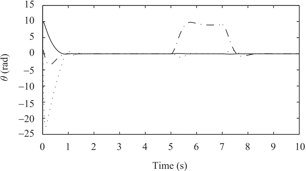
Fig.6.Outputs of ESO forθ:z1-the estimated states of system(solid line);z2-the differential of z1(dashed line);z3-the estimated overall disturbances(dash-dot line).
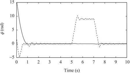
Fig.7.Outputs of roll angleφ:ADRC-based control(solid line);nonlinear PID-based control(dashed line).

Fig.8.Outputs of ESO forφ:z1-the estimated states of system(solid line);z2-the differential of z1(dashed line);z3-the estimated overall disturbances(dash-dot line).
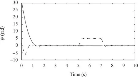
Fig.9.Outputs of yaw angleψ:ADRC-based control(solid line);nonlinear PID-based control(dashed line).

Fig.10. Outputs of ESO forψ:z1-the estimated states of system(solid line);z2-the differential of z1(dashed line);z3-the estimated overall disturbances(dash-dot line).
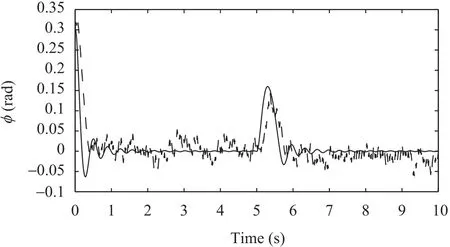
Fig.11. Outputs of roll angleφafter fault recovery:ADRC based fault tolerant control(solid line);nonlinear PID based fault tolerant control(dashed line).
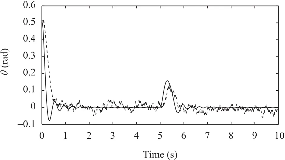
Fig.12. Outputs of pitch angleθafter fault recovery:ADRC based fault tolerant control(solid line);nonlinear PID based fault tolerant control(dashed line).
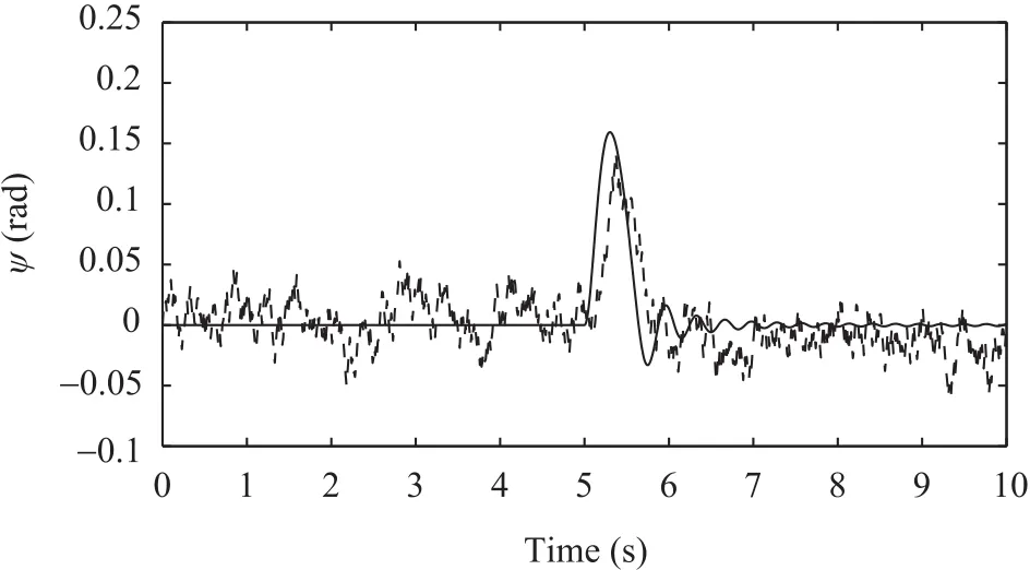
Fig.13.Outputs of yaw angleψ(rad)after fault recovery:ADRC based fault tolerant control(solid line);nonlinear PID based fault tolerant control(dashed line).

Fig.14. Outputs of vertical position z after fault recovery:ADRC based fault tolerant control(solid line);nonlinear PID based fault tolerant control(dashed line).

Fig.15. Outputs of vertical position z after fault recovery with ADRC fault tolerant control but without filtering.
2)The fault considered here assumes a 25%LOE in the first actuator att=5sec.While at hovering,the desired values are:zd=3m,φd=0°,θd=0°andψd=0°.The white Gaussian noise with zero mean value and variance of 0.01 is applied to describe measurement noises.Figs.11−15 show the outputs of quadrotor helicopter with measurement noises and actuator fault.From these figures,one can see that when actuator fault occurs,ADRC-based fault tolerant controller can still accurately control the attitude angles,since it can remarkably deal with the completely unknown uncertainties that come from both the internal and external,and it regards actuator fault as unknown uncertainties,then through compensating the uncertainties induced by the actuator faults to recover the performance of faulty system.However,comparing with ADRC-based fault tolerant control,nonlinear PID-based fault tolerant control(without filter)has larger delay,and meanwhile,it is affected seriously by measurement noises.Moreover,the attitudes are not stabilized well by nonlinear PID-based fault tolerant controller.From Figs.14(solid line)and 15,it is clear that measurement noises are well rejected by improved ESO with nonlinear function filter.
V.CONCLUSION
In this paper,a novel robust fault tolerant control strategy based on ADRC is successfully applied to stabilize an unmanned quadrotor aircraft subjecting to actuator faults and w ind gusts.An improved ESO is designed to estimate the plant dynamics and disturbances,while a nonlinear feedback control law is developed to actively suppress disturbances and accommodate actuator faults.With the accurate estimation of the plant dynamics and disturbances by ESO,the developed controller can successfully drive the outputs of quadrotor aircraft to the desired values.The proposed algorithms are validated through simulation,and the results obtained from simulation demonstrated the effectiveness of the developed control algorithm dealing with the completely unknown uncertainties that come from both internal faults and external disturbances.However,there are so many parameters of ADRC which should be carefully tuned,so ADRC with parameter adaption will be one of the focuses of our future work,also,experiments need to be carried out for fault recovery in presence of real w ind(outdoor).
[1]D.W.Murphy and J.Cycon,“Applications for mini VTOL UAV for law enforcement,”inProc.SPIE 3577,Sensors,C3I,Information,and Training Technologies for Law Enforcement,Boston,MA,USA,1999.
[2]Committee on Autonomous Vehicles in Support of Naval Operations,National Research Council,Autonomous Vehicles in Support of Naval Operations.Washington DC:The National Academies Press,2005.
[3]G.Slater,“Cooperation between UAVs in a search and destroy mission,”inAIAA Guidance,Navigation,and Control Conf.and Exhibit,Austin,Texas,USA,2003.
[4]S.R.Herwitz,L.F.Johnson,S.E.Dunagan,R.G.Higgins,D.V.Sullivan,J.Zheng,B.M.Lobitz,J.G.Leung,B.A.Gallmeyer,M.Aoyagi,R.E.Slye,and J.A.Brass,“Imaging from an unmanned aerial vehicle:Agricultural surveillance and decision support,”Comput.Electron.Agric.,vol.44,no.1,pp.49−61,Jul.2004.
[5]J.H.Kim and S.Sukkarieh,“Airborne simultaneous localisation and map building,”inProc.IEEE Int.Conf.Robotics and Automation,Taipei,Taiwan,China,2003,vol.1,pp.406−411.
[6]K.A lexis,G.Nikolakopoulos,A.Tzes,and L.Dritsas,“Coordination of helicopter UAVs for aerial forest-fire surveillance,”inApplications of Intelligent Control to Engineering Systems,K.P.Valavanis,Ed.Netherlands:Springer,2009,pp.169−193.
[7]C.Yuan,Y.M.Zhang,and Z.X.Liu,“A survey on technologies for automatic forest fire monitoring,detection,and fighting using unmanned aerial vehicles and remote sensing techniques,”Can.J.For.Res.,vol.45,no.7,pp.783−792,Mar.2015.
[8]N.Metniand T.Hamel,“A UAV for bridge inspection:Visual servoing control law with orientation limits,”Automat.Construct.,vol.17,no.1,pp.3−10,Nov.2007.
[9]Z.Sarris, “Survey of UAV applications in civilmarkets,”inProc.the 9th Mediterranean Conf.Control and Automation,Dubrovnik,Croatia,2001.
[10]X.Wang and Y.M.Zhang,“A survey on remote sensing and computer vision technologies for automatic power line inspection using unmanned aerial vehicles,”inProc.the 12th Int.Conf.Intelligent Unmanned System,Xi’an,China,2016.
[11]J.R.Azinheira and A.Moutinho,“Hover control of an UAV with back stepping design including input saturations,”IEEE Trans.Control Syst.Technol.,vol.16,no.3,pp.517−526,Apr.2008.
[12]S.Jackson,J.Tisdale,M.Kamgarpour,B.Basso,and J.K.Hedrick,“Tracking controllers for small UAVs with w ind disturbances:Theory and flight results,”inProc.the 47th IEEE Conf.Decision and Control,Cancun,Mexico,2008,pp.564−569.
[13]A.L.Jennings,R.Ordonez,and N.Ceccarelli,“An ant colony optimization using training data applied to UAV way point path planning in wind,”inProc.IEEE Swarm Intelligence Symp.,St.Louis,MO,USA,2008,pp.1−8.
[14]M.D.Hua,T.Hamel,P.Morin,and C.Samson,“A control approach for thrust-propelled under actuated vehicles and its application to VTOL drones,”IEEE Trans.Automat.Control,vol.54,no.8,pp.1837−1853,Aug.2009.
[15]K.Alexis,G.Nikolakopoulos,and A.Tzes,“Experimental model predictive attitude tracking control of a quadrotor helicopter subject to windgusts,”inProc.the 18th Mediterranean Conf.Control&Automation,Marrakech,Morocco,2010,pp.1461−1466.
[16]K.Alexis,G.Nikolakopoulos,and A.Tzes,“Constrained-control of a quadrotor helicopter for trajectory tracking under w ind-gust disturbances,”inPrco.2010 the 15th IEEE Mediterranean Electrotechnical Conf.MELECON,Valletta,Malta,2010,1411−1416.
[17]D.H.Zhou,Y.Liu,and X.He,“Review on fault diagnosis techniques for closed-loop systems,”Acta Automat.Sin.,vol.39,no.11,pp.1933−1943,Nov.2013.
[18]Y.Y.Guo and B.Jiang,“Multiple model-based adaptive reconfiguration control for actuator fault,”Acta Automat.Sin.,vol.35,no.11,pp.1452−1458,Nov.2009.
[19]M.Ranjbaran and K.Khorasani,“Generalized fault recovery of an under-actuated quadrotor aerial vehicle,”inProc.2012 American Control Conf.,Montreal,Canada,2012,2515−2520.
[20]M.Y.Zhong,S.X.Ding,and D.H.Zhou,“A new scheme of fault detection for linear discrete time-varying systems,”IEEE Trans.Automat.Control,vol.61,no.9,pp.2597−2602,Sep.2014.
[21]Y.Y.Guo,Y.M.Zhang,and B.Jiang,“Set-membership estimation based adaptive reconfiguration scheme for linear systems with disturbances,”Int.J.Adapt.Control Signal Process.,vol.30,no.2,pp.359−374,Aug.2016.
[22]M.H.Amoozgar,A.Chamseddine,and Y.M.Zhang,“Fault-tolerant fuzzy gain-scheduled PID for a quadrotor helicopter testbed in the presence of actuator faults,”IFAC Proc.Volumes,vol.45,no.3,pp.282−287,2012.
[23]J.M.Maciejowski and C.N.Jones,“MPC fault-tolerant flight control case study:flight 1862,”inProc.the 5th Symp.Fault Detection,Supervision and Safety for Technical Processes,Washington D.C.,USA,2003.
[24]T.Li,Y.M.Zhang,and B.Gordon,“Fault tolerant control applied to a quadrotor unmanned helicopter,”inProc.ASME/IEEE International Conference on Mechatronic and Embedded Systems and Applications,Washington D.C.,USA,2011.
[25]H.Bouadi,M.Bouchoucha,and M.Tadjine,“Sliding mode control based on back stepping approach for an UAV type quadrotor,”Int.J.Appl.Math.Comput.Sci.,vol.4,no.1,pp.12−17,2007.
[26]J.Q.Han,“From PID technique to active disturbances rejection control technique,”Control Eng.China,vol.9,no.3,pp.13−18,May2002.
[27]L.E.Munõz,P.Castillo,G.Sanahuja,and O.Santos,“Embedded robust nonlinear control for a four-rotor rotorcraft:validation in real-time with wind disturbances,”inProc.2011 IEEE/RSJ Int.Conf.Intelligent Robots and Systems,San Francisco,CA,USA,2011,2682−2687.
[28]S.Salazar,H.Romero,R.Lozano,and P.Castillo,“Modeling and realtime stabilization of an aircraft having eight rotors,”J.Intell.Robot.Syst.,vol.54,no.1−3,pp.455−470,Mar.2009.
[29]T.Bresciani,“Modelling,identification and control of a quadrotor helicopter,”M.S.thesis,Dept.Automat.Control,Lund Univ.,Lund,2008,22−27.
[30]Y.L.He,Y.M.Chen,and M.F.Zhou,“Modeling and control of a quadrotor helicopter under impact of w ind disturbance,”J.Chin.Inert.Technol.,vol.21,no.5,pp.624−630,Oct.2013.
杂志排行
IEEE/CAA Journal of Automatica Sinica的其它文章
- Encoding-Decoding-Based Control and Filtering of Networked Systems:Insights,Developments and Opportunities
- Internet of Vehicles in Big Data Era
- Residential Energy Scheduling for Variable Weather Solar Energy Based on AdaptiveDynamic Programming
- From Mind to Products:Towards Social Manufacturing and Service
- Analysis of Autopilot Disengagements Occurring During Autonomous Vehicle Testing
- A Methodology for Reliability of WSN Based on Software De fined Network in Adaptive Industrial Environment
