Effect of the Diameter of Carbon Nanotubes Supporting Platinum Nanoparticles on the Electrocatalytic Oxygen Reduction
2018-01-11YUJingHuaLIWenWenZHUHong
YU Jing-Hua LI Wen-Wen ZHU Hong
Effect of the Diameter of Carbon Nanotubes Supporting Platinum Nanoparticles on the Electrocatalytic Oxygen Reduction
YU Jing-Hua LI Wen-Wen ZHU Hong*
()
A series of nanocatalysts consisting of acid treated carbon nanotubes (CNTs) with different diameters (8–15, 20–30, 30–50, >50 nm) supporting platinum (Pt) nanoparticles (Pt/CNTs) were synthesizeda microwave-assisted ethylene glycol method. The as-synthesized catalysts were characterized by X-ray photoelectron spectroscopy (XPS), X-ray diffraction (XRD), thermogravimetric analysis (TGA), and transmission electron microscopy (TEM). Their catalytic performances in the oxygen reduction reaction (ORR) were evaluated by cyclic voltammetry (CV) and linear sweep voltammetry (LSV). The experimental results showed that the diameter of the CNTs influences the particle size, loading, and dispersion of Pt NPs. Furthermore, the Pt/CNTs having different CNT diameters displayed different catalytic activities in the ORR. The catalyst Pt/CNT8, which was prepared by using CNTs with diameters ranging between 8−15 nm as the support, exhibited the highest Pt loading, catalytic activity, and stability in the ORR. The mass activity of Pt/CNT8was determined to be 0.188 A∙mg−1at 0.9 V, which is folds higher than that of the commercially available JM Pt/C catalyst. After testing the stability for 5000 potential cycles, the negative shift (~7 mV) of the half-wave potential for Pt/CNT8was found to be significantly lesser than that for the JM Pt/C catalyst (~32 mV), indicating superior catalytic stability.
Microwave-assistance; Platinum; Carbon nanotubes; Diameter effect; Stability
1 Introduction
The fossil fuel reduction and increasingly serious environmental pollution have made it urgent to search for new impetus to cars. Proton exchange membrane fuel cell (PEMFC), a new focus of the material industry, has attracted growing attention owing to its high energy conversion efficiency and low pollution emission. Years of basic research and development suggest that substantial progress has been made in research on PEMFC as a vehicle power. It is considered as one major energy technology in the 21st century and as the future of traffic power1–3. Because the catalyst is critical in the fuel cell, its carrier plays an extremely important role in the catalyst and its electrochemical reaction. The physical properties and surface chemical properties of the carrier significantly affect the catalytic activity and performance of the whole battery4.Therefore, selecting a catalyst carrier is particularly important. An appropriate carrier of PEMFC anode catalysts should satisfy two conditions: (i) large specific surface area and high electrical conductivity, and (ii) stability in the harsh working environment of PEMFC5,6. Various carbon-based materials can be used as carriers, such as carbon black7–9, activated carbon fibers10, mesoporous carbon11–13, carbon paper14,15, and carbon nanotubes (CNTs)16–18.
CNTs have received extensive attention as a new catalyst carrier in recent years19–27. CNTs can fill in and adsorb particles because of their tubular structure, singular conductivity and very large specific surface area, and they are highly stable in many conditions, which make CNTs a very promising catalyst carrier28,29. Therefore, CNT-supported catalysts have special appeal in electron transport of catalytic process30.With CNTs as a support, however, the major concern is the deposition method that generates highly-dispersed metal particles on the surfaces of CNTs. Pt deposits onto CNTs through complication between the Pt2+precursor and the C=C fragments atop the support. Because the number of reactive C=C fragments at the nanotube surfaces is limited, the deposition of metal precursors per unit surface area is hindered31,32. The most advanced strategy to increase the number of available anchoring sites is to functionalize the nanotube surfaces through chemical or physical treatments33. For this issue, many efforts have been devoted to the roles of oxygen-containing surface groups, which anchor nanoparticles and thereby promote the deposition of metallic nanoparticles onto carbon surfaces34. Although the presence of oxygen-bearing groups may not promote Pt incorporation, it stabilizes the catalysts by increasing the interaction strength between the Pt particles and the support35–38. Additionally, the presence of surface functional groups increases the hydrophilicity of the catalysts, favoring the diffusion of the reactants toward the active sites39. In addition, CNTs are composed of thickness-varying graphite curls, and the carbon atoms in the graphite layers aresphybrid. Each carbon atom has an unpaired electron located in thetrack perpendicular to the layer40. Due to the quantum confinement effect, electrons can only move in the axial direction of the tubes in the graphite sheet. Thus, the electrical properties are affected by the tube diameter/length, the spiral structure of the winding, and other factors.
In this paper, the modified CNTs supported Pt nanoparticles (NPs) were synthesized through a microwave-assisted homogeneous deposition strategy, in which ethylene glycol was used as the solvent and reducing agent of Pt precursor. This fast and easy-to-operate process ensured uniform heating and low-cost; besides, it can effectively increase the dispersion as well as loading of Pt NPs on the CNTs. Moreover, the Pt/CNT catalysts were compared to the commercially available VC supported Pt (20% (, mass fraction)) catalyst from Johnson Matthey.
2 Experimental
2.1 Functionalization of CNTs and synthesis of electrocatalysts
Four batches of multi-walled CNTs with purity >95% were obtained from Nanjing XFNANO Materials Tech Co., Ltd. (China) with mean diameters of 8–15 nm (CNT8), 20–30 nm (CNT20), 30–50 nm (CNT30), and >50 nm (CNT50), respectively. The CNTs were treated in acid to eliminate impurities and create surface oxygen groups. Then each gram of CNTs was dispersed in 270 mL of a sulfonitric mixture (concentrated sulfuric acid and nitric acid in the volume ratio of 1 : 3), refluxed at room temperature for 1 h, and then transferred to an oil bath at 100°C under backflow mixing for 4 h. Afterward, the reaction vessel was cooled down to room temperature and filled with distilled water (ca. 2 L). The solids were recovered by filtration, washed thoroughly with distilled water until the filtrate was about pH 7.0, and dried overnight at 60°C.
The functionalized CNTs were used as the support for 20% () Pt in the catalysts. Each time, about 80 mg of the functionalized CNTs was dispersed in 40 mL of ethylene glycol (EG) and ultrasonicated for 30 min. Then 2.7 mL of a solution of H2PtCl6×6H2O in EG (0.02 g×mL−1) was added dropwise to a CNTs suspension under vigorous stirring for 40 min at room temperature. Then the solution was adjusted to about pH 10 by using a KOH/EG solution, removed to the microwave reactor and heated at 170°C for 30 min. EG was used as both the reducing agent and the solvent here. Afterward, the Pt/CNT were washed with deionized water and dried at 60°C overnight.
2.2 Structural and compositional characterization
The prepared catalysts were analyzed on an X-ray diffractometer (XRD) (Shimazdou, XD-3A) within the Bragg’s angles (2) from 5° to 90° at a speed of 7 (°)·min−1. The crystal phases with the corresponding diffraction lines were implemented by comparison with powder diffraction files (PDF) from International Centre for Diffraction Data (ICDD). The average crystallite sizewas estimated from the diffraction peak of Pt (220) by using the Debye-Scherrer equation (Eq.(1))41:
= 0.9λ1/(cosmax) (1)
whereλ1is the X-ray wavelength,maxis the maximum angle of the (220) peak, andis the full-width at half-maximum in radians. The loss curves of Pt/CNT catalysts were measuredthermogravimetric analysis (TGA). Usually, 20–30 mg of a catalyst was heated from 298 to 1098 K at 7 K·min−1and air atmosphere. The morphology of the catalyst was observed on a transmission electron microscope (TEM, JEOL JEM-3010HR, Japan). Raman spectra of the CNTs and after treatment CNTs were recorded using a 1000 spectrometer equipped with a 100 mW laser with emission at 532 nm equipped with a thermoelectrically cooled CCD detector. X-ray photoelectron spectroscopy (XPS) measurements were performed with a VG Scientific ESCALAB 250 electron spectrometer using Al KR radiation under a vacuum of 2´10−8Pa.
2.3 Electrochemical characterization
The electrochemical tests were performed on a three-electrode work station (Zahner, Germany), with a platinum wire used as the counter electrode and a saturated calomel electrode as the reference electrode. The reported potential was relative to the reversible hydrogen electrode potential (RHE). The catalysts were dropped onto the surfaces of the glassy carbon (GC) electrode (5 mm diameter) with an ink42. The GC was already polished (50 nm alumina) to a mirror finish and ultrasonically cleaned with deionized water. Theoretically, 20.4mg∙cm−2of Pt was deposited onto the working electrode. Each time a 2 mg of the catalyst was dispersed in 3 mL of deionized water, 7 mL of isopropanol, and 40mL of Nafion by sonication. Subsequently, 20mL of the ink was dropped onto the GC surfaces until the catalyst was totally dried at room temperature. The catalysts were treated by 50 cyclic scans from 0.05 to 1.1 V at 50 mV∙s−1. Before the electrochemical tests, the working electrode was electrochemically cleaned and stabilized by 20 cycles between 0.05 and 1.1 V at 100 mV∙s−1. The ORR performance of each catalyst was studied with a conventional rotating disk electrode (RDE). The catalysts (deposited onto the GC electrode) were immersed in an O2-saturated 0.1 mol∙L−1HClO4electrolyte at the cyclic potential between 1.1 and 0.05 V at 20 mV∙s−1and 1600 r∙min−1until the current was stable. The accelerated stability of the catalyst was studied at a scan rate of 50 mV∙s−1at 0.60 and 1.00 V (. RHE) repeated scanning for 5000 cycles in N2-protected 0.1 mol∙L−1HClO4. Before any stability test, the catalyst supported on the electrode was cycled between 0.05 and 1.10 V at a scan rate of 100 mV∙s−150 cycles.
3 Results and discussion
3.1 Physicochemical characterization
Raman spectra of the initial and functionalized CNTs are both presented in Fig.1. The most prominent features in all Raman spectra are a set of bands at about 1350 and 1580 cm−1that are usually referred to as theandbands, respectively. Theband andband account for the complete structure of the graphite layer and the defect structure of nanotube walls, respectively. The increase of theI/Iratio suggests the improvement of defect degree. The evolution of theI/Iratios in Fig.1 indicates that the chemical treatment moderately increases the amount of defects in the CNTs. Therefore, theI/Iratio of CNT8after acid treatment is the highest relative to other CNTs, which suggests the presence of more defects in CNT8. Due to the larger specific surface area, the smaller-diameter CNTs contain more surface defects that are beneficial to the loading of Pt metal.
The crystalline structures of the Pt/CNT catalysts analyzed by powder XRD are showed in Fig.2. Specifically, the four major peaks at 2= 39.7°, 46.2°, 67.5°, 81.4° are attributed to the (111), (200), (220) and (211) peaks of Pt, respectively (JCPDS 04-0802)43. The peaks at around 40°, 46°, 67° and 81° can be attributed to the diffraction from CNTs. These results indicate the successful preparation of Pt/CNT catalysts. The Pt crystallite sizes of Pt/CNT8, Pt/CNT20, Pt/CNT30and Pt/CNT50calculated by Eq.(1) are 4.32, 4.73, 4.94 and 5.02 nm, respectively, which indicates the deposition of Pt nanocrystals can be affected by the tube diameter.
Fig.3 displays the TEM graphs of the Pt/CNT catalysts and the corresponding particle size distributions plotted by counting at least 150 particles on each catalyst. The TEM graphs confirm that the nanotube diameters change in the order of CNT50> CNT30> CNT20> CNT8. Moreover, the Pt particles in Pt/CNT8have a mean diameter of about 3.58 nm and a narrow particle size distribution. The averages sizes of Pt particles in Pt/CNT20, Pt/CNT30and Pt/CNT50are 4.46, 4.71 and 5.34 nm, respectively, which agree with the crystallite sizes calculated by XRD and confirm that the Pt particle size increases with the tube diameter. The possible reason is the surface area of CNTs. Due to the smaller specific surface area of the larger-diameter CNTs, the limited surface sites lead to the formation of relatively large-size particles. Clearly, the appropriate surface area of CNTs also plays an important role in the size and dispersion of the Pt nanoparticles.

Fig.1 Raman spectra of the initial (red line), functionalized (back line) CNTs.
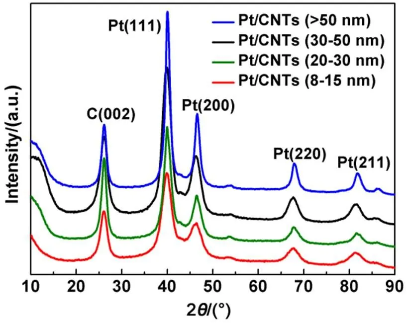
Fig.2 XRD patterns of Pt/CNT catalysts with different tube diameters.
The TG profiles of the Pt/CNT catalysts are displayed in Fig.4. The loads of Pt on the diameter-varying CNTs are significantly different. The most relevant difference in the TG profiles is the beginning temperature of weight loss which shifts from ca. 450°C in Pt/CNT8, Pt/CNT20and Pt/CNT30to ca. 520°C in Pt/CNT50. CNT50also has a higher onset temperature. This is because the thermal stability of CNTs changes with the tube diameters and is improved at the nanotube diameters above 50 nm. The CNTs incorporation of Pt seems to enhance the differences. The Pt loads of the Pt/CNT change in the order of Pt/CNT8(19.6% ()) > Pt/CNT20(17.2% ()) > Pt/CNT30(16.7% ()) > Pt/CNT50(16.5% ()).
X-ray photoelectron spectroscopy (XPS) spectra characterizing the chemical state information of the Pt 4of the Pt/CNT catalysts are shown in Fig.5. The Pt 4region shows doublet peaks at 71.2 and 74.3 eV, which are attributed to Pt047/2and Pt045/2, respectively. The two pairs of peaks from the spin-orbital split of the 47/2and 45/2regions were due to Pt(II) and Pt(IV) valence states, respectively. The atomic compositions of different Pt species calculated based on the Pt 4spectra of Pt/CNT catalysts are shown in Table 1. The catalysts show different ratios of metallic Pt to oxide species. This composition suggests a basically complete reduction of the adsorbed Pt(IV) complex species by the EG, implying that the microwave-assisted ethylene glycol strategy is highly efficient for preparation of high Pt-load catalysts with the support of CNTs. Therefore, the Pt load was the highest in the case of 8–15 nm CNTs, which improves the efficiency of the catalysts.

Fig.3 TEM patterns for (a) Pt/CNT8, (b) Pt/CNT20, (c) Pt/CNT30, and (d) Pt/CNT50 and the corresponding histograms of particle sizes distribution.
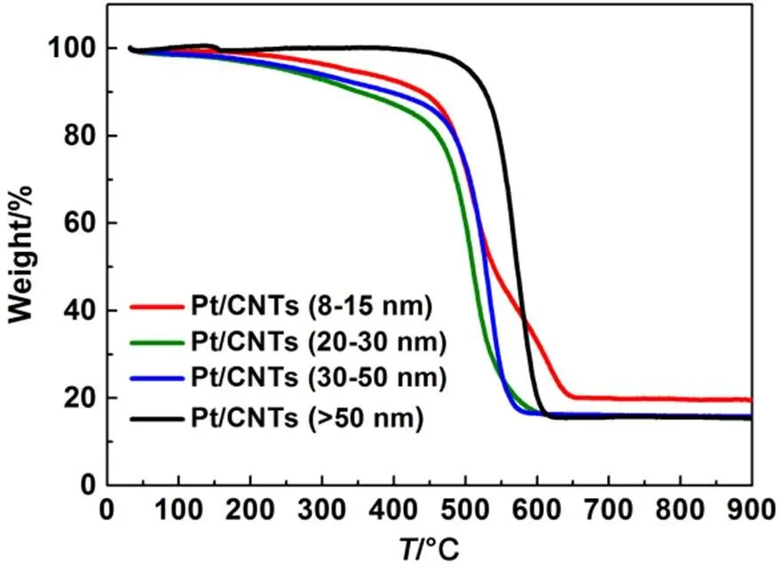
Fig.4 TG profiles recorded in air of Pt/CNT catalysts with different diameters of CNTs.

Fig.5 XPS spectra of (a) Pt/CNT8, (b) Pt/CNT20, (c) Pt/CNT30, (d) Pt/CNT50.

Table 1 The atomic ratio (x) of Pt(0)/Pt(II)/Pt(IV) of Pt/CNT catal1ysts.
3.2 Electrocatalytic performance of catalysts
The CVs of the Pt/CNT catalysts are shown in Fig.6. The catalysts show significant differences in the hydrogen absorption peak at 0.05–0.4 V and the oxygen reduction peak at 0.7–0.9 V. The electrochemical surface area (ESA) was calculated by integrating the hydrogen desorption area in the range of 0.075 to 0.35 V as follows:
ESAPt= {H/[0.21 ×pt×g]} × 10 (2)
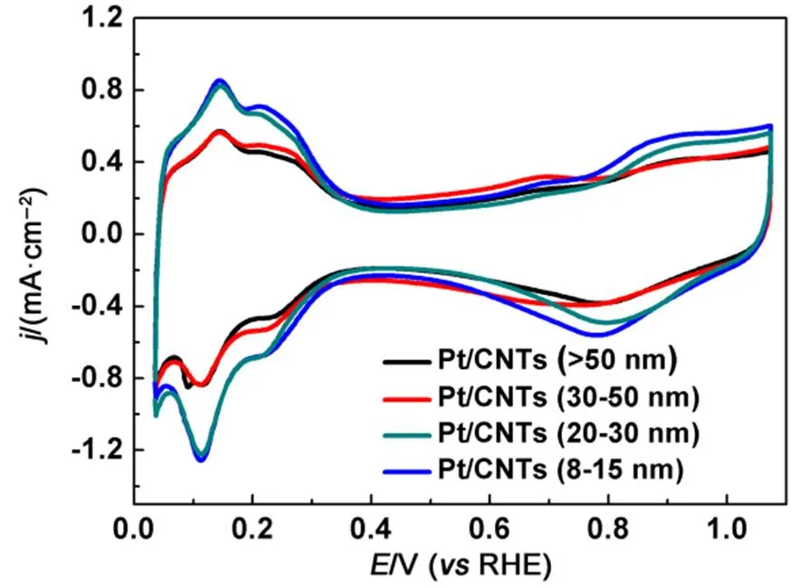
Fig.6 CV curves for Pt/CNT catalysts with different diameters of CNTs.
All measurements were made in N2-purged 0.1 mol∙L−1HClO4at room temperature. Sweep rate: 50 mV s−1.
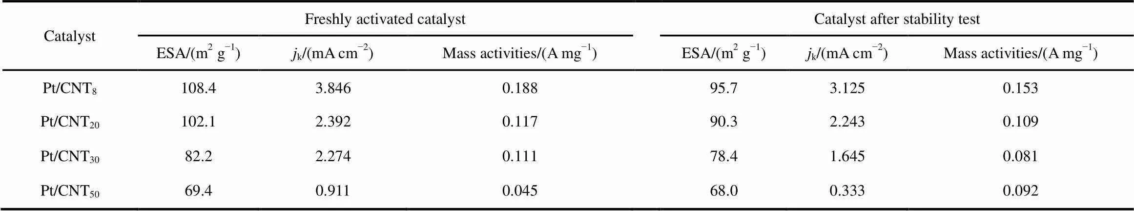
Table 2 Electrochemical properties of the Pt/CNTbefore and after stability test.
whereH(mC) is the charge required during hydrogen adsorption on the Pt surface,Pt(mg∙cm−2) is the of Pt loading on the working electrode, andg(cm2) is the surface area of the GC electrode (i.e., 0.196 cm2)44. The ESAPt(m2∙g−1) of JM Pt/C, Pt/CNT8, Pt/CNT20, Pt/CNT30and Pt/CNT50calculated by Eq.(2)is 53.52, 108.4, 102.1, 82.2 and 69.4 m2∙g−1, respectively. As for the differences, the possible reason is that CNTs with smaller tube diameter and larger specific surface area contain more functional groups, so more Pt (0) is loaded and the particles are smaller, leading to larger electrochemical active area of the catalysts. Interestingly, the onset potential of the oxide formation region shifts to lower positive level as the Pt particle size decreases, indicating that the catalysts become more oxophilic with the decrease of particle size.
The RDE was operated at 1600 r∙min−1to measure the mass activities of the catalysts. The polarization curves of the Pt/CNT catalysts are shown in Fig.7(a), with the JM Pt/C catalyst for comparison. Moreover, the mass activities of the catalysts were compared by calculating the kinetic current densitykas follows45:

Fig.7 (a) Polarization curves and (b) mass activities for Pt/CNT catalysts with different diameters of CNTs and JM Pt/C.
Measurements were made in O2-saturated 0.1 mol∙L−1HClO4at a rotation rate of 1600 r∙min−1.
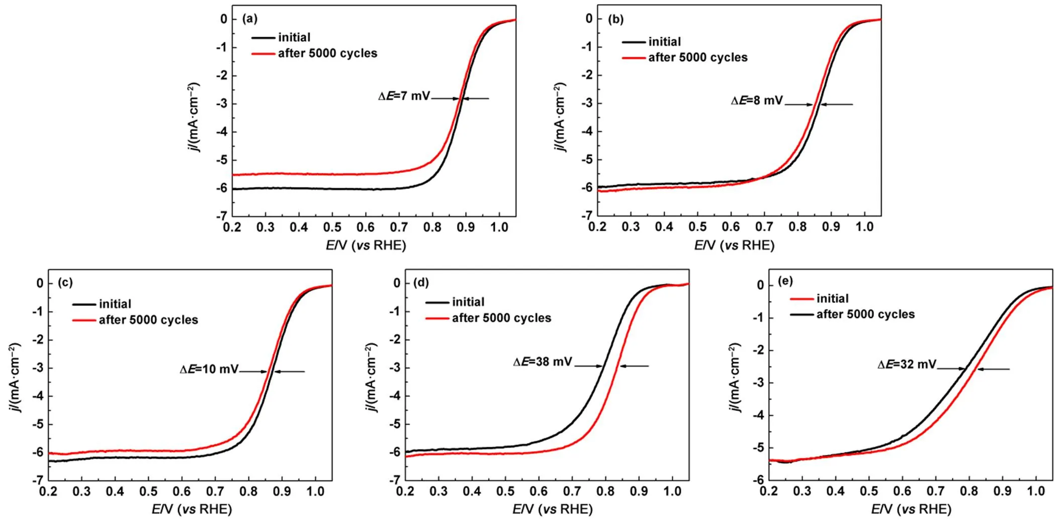
Fig.8 Electrochemical durability for (a) Pt/CNT8, (b) Pt/CNT20, (c) Pt/CNT30, (d) Pt/CNT50, and JM Pt/C.
k= (lim×)/(lim−) (3)
wherelimis the current density at= 0.4 V, andis the current density at= 0.9 V. The mass activity of Pt was estimated by calculation ofk. The Pt mass activities of JM Pt/C, Pt/CNT8, Pt/CNT20, Pt/CNT30and Pt/CNT50at 0.9 V are 0.071, 0.188, 0.117, 0.092, and 0.045 A∙mg−1, respectively, indicating the highest activity of the Pt/CNT8catalysts is over 2 times higher than JM Pt/C (Fig.7(b)). The catalytic activities follow the order of Pt/CNT8> Pt/CNT20> Pt/CNT30> JM Pt/C > Pt/CNT50. Therefore, the ORR activities were linear dependence with diameter of CNTs support.
Accelerated durability tests were conducted under cycling potential sweeps at 50 mV∙s−1between 0.6 and 1.1 V. RHE and by measuring the electrochemical property changes (Fig.8 and Table 2). After 5000 cycles, the negative shifts of Pt/CNT8, Pt/CNT20, Pt/CNT30and Pt/CNT50at half-wave potential are 7, 8, 10 and 38 mV, respectively. Their retained Pt mass activities are 81%, 80%, 72% and 35%, respectively. Pt/CNT8shows a significant durability compared with other catalysts, because the support of CNTs could reduce Pt degradation and loss. Meanwhile, the current densityis thelargest in the case of the smallest-diameter CNTs. Therefore, the ESA of each Pt/CNT catalyst before andafter the durability tests were also measured. It was found the losses of ESA in Pt/CNT8, Pt/CNT20, Pt/CNT30and Pt/CNT50were 4.6%, 11%, 14.9% and 2.0%, respectively. These results indicate the ESA of catalysts are stable when the CNTs are used as a catalyst carrier.
4 Conclusions
We demonstrated the synthesis of a series of CNTs supported Pt NPs catalysts with different diameters of CNTs through a microwave-assisted homogeneous deposition strategy, followed by reduction using ethylene glycol as the precursor of a reducing agent, and the modified CNTs were used to support. XPS, XRD, TG, and TEM measurements show that this method allows us to deposit high-loading Pt nanoparticles monodisper sed on CNTs, and the diameter of CNTs affects the loading and particle size of the Pt deposited onto CNTs. The Pt loading increases with decreased of tube diameter. At a nanotube diameter of 8−15 nm, the Pt loaded on the CNTs is homogeneous with small particle size (~3.5 nm), which account for both the larger specific surface area of the smaller-diameter nanotubes and the larger number of oxygen-containing surface groups after chemical treatment. Consequently, the catalytic ORR performance is affected by the nanotube diameter. In comparison, Pt/CNT8has the highest ORR activity. Pt/CNT8, Pt/CNT20and Pt/CNT30all have much higher electrochemical activity than JM Pt/C. The stability of a Pt/CNT catalyst is increased when Pt is supported on smaller-diameter CNT8because the larger Pt particles and numerous oxygen groups on CNT8promote the interaction between the Pt particles and the support.
(1) Frederick, T. W.; Balasubramanian, L.; Mark, F. M.2010,, 2204. doi: 10.1021/jz100553m
(2) Debe, M. K.2012,, 43. doi: 10.1038/nature11115
(3) Yi, B. L. Fuel Cells—Principle technologies and applications. Chemical Industry Press: Beijing, 2003. [衣宝廉. 燃料电池: 原理·技术·应用. 北京: 化学工业出版社, 2003. ]
(4) Li, W. Z.; Liang, C. H.; Zhou, W. J.2003,, 6292. doi: 10.1021/jp022505c
(5) Stoyanova, A.; Naldenov, V.; Petrov, K.; Nikolov, I.; Vitanov, T.; Budevski, E.1999,, 1197. doi: 10.1023/A:1003482613323
(6) Aricò, A.S.; Stassi, A.; Modica, E.; Ornelas, R.; Gatto, I.; Passalacqua, E.; Antonucci, V.2008,, 525. doi: 10.1016/j. jpowsour.2007.1 0.005
(7) Wang, J. J.; Yin, G. P.; Shao, Y. Y.; Zhang, S.; Wang, Z. B.; Gao, Y. Z.2007,, 331. doi: 10.1016/j.jpowsour.2007.06.084
(8) Zhang, C. L.; Wang, S. Y.; Peng, Z. M.2014,, 19778. doi: 10.1039/C4TA04728A
(9) Stamenkovic, V. R.; Mun, B. S.; Arenz, M.; Mayrhofer, K. J.; Lucas, C. A.; Wang, G.; Ross, P. N.; Markovic, N. M.2007,, 241. doi: 10.1038/nmat1840
(10) Huang, H. X.; Chen, S. X.; Yuan, C.2008,, 166. doi: 10.1016/j.jpowsour.2007..107
(11) Sun, Z. P.; Zhang, X. G.; Liang, Y. Y.; Tong, H.; Xue, R. L.; Yang, S. D.; Li, H. L.2009,, 1. doi: 10.1016/j.jelechem.2009.04.013
(12) Ahn, S. H.; Kwon, O. J.; Kim, S. K.; Choi, I.; Kim, J. J.2010,, 13309. doi: 10.1016/j.ijhydene.2010.09.035
(13) Wan, K.; Long, G.; Liu, M.; Du, L.; Liang, Z.; Tsiakaras, P.2015,, 566. doi: 10.1016/j.apcatb.2014.10.054
(14) Viva, F. A.; Bruno, M. M.; Franceschini, E. A.; Thomas, Y. R. J.; Ramos S. G.; Solorza-Feria, O.; Corti, H. R.2014,, 8821. doi: 10.1016/j.ijhydene.2013.12.027
(15) Madhu, S. S.; Mohammad, N. B.; Zhang, Y.; Li, R. Y.; Sun X. L.; Cai, M.; Frederick, T. W.2009,, 330. doi: 10.1016/j.jpowsour.200 9.02.087
(16) Tong, H.; Li, H. L.; Zhang, X. G.2007,, 2424. doi:10.1016/j.carbon.2007.06.028
(17) Walid, M. D.; Toyoko, I.2015,, 392. doi: 10.1080/17458080.2013.838703
(18) Zhang, Y.; Hu, J. S.; Wei, Z. D.; Wan L. J.2015,, 2903.10.1021/acscatal.5b00117
(19) Guo, L.; Chen, S. G.; Wei, Z. D.2014,, 387. doi: org/10.1016/j.jpowsour.2014.01.040
(20) Gong, K.; Du, F.; Xia, Z.; Durstock, M.; Dai, L.2009,, 760. doi: 10.1126/science.1168049
(21) Guo, L.; Chen, S. G.; Li, L.; Wei, Z. D.2014,, 360. doi: org/10.1016/j.jpowsour.2013.08.102
(22) Wang, X.; Li, W. Z.; Chen, Z. W.; Wa, J. M.; Yan, Y. S.2006,, 154. doi: 10.1016/j.jpowsour.2005.09.039
(23) Wu, G.; Xu, B. Q.;.2007,, 148. doi:10.1016/j.jpowsour. 2007. 08.024
(24) Zhao, Y. C.; Lan, H. X.; Deng, B. B.; Tian, J. N.; Yang, X. L.; Wang, F. Y.. 2010,, 2255. [赵彦春, 兰黄鲜, 邓彬彬, 田建袅, 杨秀林, 王凤阳. 物理化学学报, 2010,, 2255.] doi: 10.3866/PKU.WHXB20100829
(25) Chen, Y.; Tang, Y. W.; Kong L. Y.; LIU, C. P.; XING, W.; LU, T. H.. 2006,, 119. [陈 煜, 唐亚文, 孔令涌, 刘长鹏, 邢 巍, 陆天虹. 物理化学学报, 2006,, 119.] doi: 10.3866/PKU.WHXB20060124
(26) Hsieh, C. T.; Gu, J. L.; Tzou, D. Y.; Chu, Y. C.; Chen, Y. C.2013,, 10345. doi: 10.1016/j.ijhydene.2013.05.146
(27) He, D. P.; Zeng, C.; Xu, C.; Cheng N. C.; Li, H. G.; Mu, S. C.; Pan, M.2011,, 5582. doi: 10.1021/la2003589
(28) Li, X. G.; Hsing, I.2006,, 5250. doi: 10.1016/j.electacta.20 06.01.046
(29) Tao, L.; Dou, S.; Ma, Z. L; Wang, S. Y.2015,, 46. doi: 10.1016/j.electacta.2015.01.054
(30) Fang, B. Z.; Kim, M. S.; Kim, J. H.; Song, M. Y.; Wang Y. J.; Wang, H. J.; Wilkinson, D. P.; Yu J. S.2011,, 8066 doi: 10.1039/C1JM10847F
(31) Kong, B. S.; Jung, D. H.; Oh, S. K.; Han, C. S.; Jung, H. T...2007,, 8377. doi: 10.1021/jp071297r
(32) Nie, Y.; Li, L.; Wei, Z. D.... 2015,, 2168. doi: 10.1039/C4CS00484A
(33) Yu, R. Q; Chen, L. W.; Liu Q. Q.; Lin J. Y.; Tan, K. Lee.; Siu, C. N.; Chan, H. S. O.; Xu G. Q.; Hor, T. S. A..1998,, 718. doi: 10.1021/cm970364z
(34) Star, A.; Liu, Y.; Grant, K.;Ridvan, L.; Stoddart, J. F.; Steuerman, D. W.; Diehl, M. R.; Boukai, A.; Heath, J. R.2003,, 553. doi: 10.1021/ma021417n
(35) Soin, N.; Roy, S. S.; Karlsson, L.; McLaughlin, J. A. Diamond Relat Mater 2010,, 595. doi: 10.1016/j.diamond.2009.10.029
(36) He, D. P.; Mu, S. C; Pan, M.2011,, 82. doi: 10.1016/j. carbon.2010.0 8.045
(37) Mu, Y.; Liang, H.; Hu, J.; Jiang, L.; Wan, L. J...2005,, 22212. doi: 10.1021/jp0555448
(38) Liu, Z. L.; Lin, X. H.; Lee, J. Y.; Zhang, W.; Han, M.; Gan, L. M.2002,, 4054. doi: 10.1021/la0116903
(39) Kongkanand, A.; Kuwabata, S.; Girishkumar, G.; Kamat, P.2006,, 2392. doi: 10.1021/la052753a
(40) Liu, J. B.; Yuan, Y.; Bashir, S.2013,, 6476. doi: 10.3390/en6126476
(41) Zhao, Y. C.; Yang, X. L.; Tian, J. N.2009,, 7114. doi: 10.1016/j.electacta.2009.07.021
(42) Yu, H.; Zeng, K.; Fu, X. B.; Zhang, Yan.; Peng, F.; Wang, H. J.; Yang, J.2008,, 11875. doi: 10.1021/jp804003g
(43) Hussain, S.; Pal, A. K.2008,, 1874. doi: 10.1016/j.matlet.2007.10.021
(44) Luo, M. C.; Wei, L. L.; Wang, F. W.; Han, K. F.; Zhu, H.2014,, 34. doi: 10.1016/j.jpowsour.2014.07.102
(45) Zhu, H.; Luo, M. C.; Zhang, S.; Wei, L. L.; Wang, F. W.; Wang, Z. G.; Wei, Y. S.; Han, K. F.2013,,3323. doi: 10.1016/j.ijhydene.2012.12.12
管径对碳纳米管负载铂催化剂氧还原的影响
于景华 李文文 朱 红*
(北京化工大学理学院,化工资源有效利用国家重点实验室,北京 100029)
采用微波辅助乙二醇法制备了一系列酸处理后的不同管径(8–15,20–30,30–50,>50 nm)的碳纳米管(CNT)负载铂(Pt)催化剂(Pt/CNT)。通过X射线光电子能谱(XPS)、X射线衍射(XRD)、热重分析仪(TGA)、透射电子显微镜(TEM)对所制得催化剂进行结构表征;采用循环伏安法(CV)和线性扫描伏安法(LSV)对其催化性能进行测试。结果表明,不同管径的碳纳米管对Pt的粒径、载量和分散性有一定程度影响;然而,不同CNT管径的催化剂表现出明显不同的催化氧还原反应(ORR)活性。采用管径为8–15 nm的CNT作为载体制备的催化剂(Pt/CNT8)的Pt载量最高,表现出有很好的催化活性和稳定性。Pt/CNT8在0.9 V时Pt的质量活性为0.188 A∙mg−1,是商业催化剂(JM Pt/C)的2倍。经扫描5000圈稳定性测试之后,Pt/CNT8的半波电位负移(~7 mV)远远小于商业JM Pt/C半波电位的负移(~32 mV),表现出优越的催化ORR稳定性。
微波辅助;铂;碳纳米管;管径效应;稳定性
O646
10.3866/PKU.WHXB201705052
March 23, 2017;
April 24, 2017;
May 5, 2017.
. Email: zhuho128@126.com; Tel: +86-10-64444919.
The project was supported by the Beijing Municipal Science and Technology Program, China (Z171100000917019), the National Key Research and Development Program of China (2016YFB0101203), the National Natural Science Foundation of China (21376022, 21476020), International S&T Cooperation Program of China (2013DFA51860), and Fundamental Research Funds for the Central Universities, China (JC1504).
北京市科技计划(Z171100000917019), 国家重点基础研究发展计划(2016YFB0101203), 国家自然科学基金(21376022, 21476020), 国际科技合作项目(2013DFA51860)和中央高校基本科研业务费(JC1504)资助
猜你喜欢
杂志排行
物理化学学报的其它文章
- 重元素多重金属-金属键的新发现:U≡Fe三重键
- 卤化钙钛矿太阳能电池材料理论研究进展
- Development and Validation of a Reduced Chemical Kinetic Mechanism for HCCI Engine of Biodiesel Surrogate
- 非离子表面活性剂Triton X-100溶液在不同生长期小麦叶片表面的润湿行为
- Efficient Synthesis of Sulfur and Nitrogen Co-Doped Porous Carbon by Microwave-Assisted Pyrolysis of Ionic Liquid
- First-Principles Study: the Structural Stability and Sulfur Anion Redox of Li1−xNiO2−ySy