First-Principles Study: the Structural Stability and Sulfur Anion Redox of Li1−xNiO2−ySy
2018-01-10YANHuiJunLIBiaoJIANGNingXIADingGuo
YAN Hui-Jun LI Biao JIANG Ning XIA Ding-Guo
First-Principles Study: the Structural Stability and Sulfur Anion Redox of Li1−xNiO2−yS
YAN Hui-Jun LI Biao JIANG Ning XIA Ding-Guo*
()
Ni-rich layered oxides are the preferred cathode materials for high-energy-density lithium-ion batteries currently used in electric vehicles. In this paper, we present a systematic first-principles evaluation of the deintercalation process in the Li1−NiO2−yS. The partial density of states (PDOS) characters of the electrons near the Fermi level, redox behaviors, and thermal stability have been investigated within the GGA +scheme. The results show that the introduction of sulfur alleviates the lattice distortion during charging, suppresses nickel migration, and enhances the stability of oxygen according to the contribution of sulfur anion redox to the charge compensation for the overcharged Li1−NiO2−S. This study provides a new insight on improving the stability of Ni-rich cathode materials by tuning of the electrochemical behaviors based on sulfur anion redox.
Anion doping; Sulfur redox; Structural stability; Thermal stability; Transition metal migration
1 Introduction
Ni-rich layered oxides with high energy density and low cost are the preferred cathode material for the high energy density lithium-ion batteries used in electric vehicle1,2. For instance, lithium-ion batteries with LiNi0.8Co0.15Al0.05O2have been successfully applied in Tesla. However, Ni-rich layered cathodes suffer from the serious safety concern, related to the structural instability and oxygen release in their overcharged states3,4. Numerous works were done to improve the electrochemical performance of the layered Ni-rich cathodes. Cation doping is a good strategy to enhance the safety of layered Ni-rich oxides and have been extensively verified by experiments5−7. Most cation doping improves structural stability and safety of Ni-rich cathodes through the increased bonding strength of TM―O bond and the decreased oxygen evolution8. Anion doping also attracts researchers' attention9,10. The cycling stability of layered Ni-rich oxides was enhanced by fluorine substitution, which protected the electrode from HF-acid attack11. Park.12suggested that sulfur doping in LiNiO2enhanced the capacity retention by improving the structural stability. Kongstudied the conflicting roles of anion doping (F, Cl and S) in LiNiO2by the first-principles calculations13. However, these works were done by assuming that the electrochemical behaviors of this conventional layered oxide are mainly from the contribution of cation redox during charge-discharge process. By contrast, the abnormally high capacities delivered by lithium-rich oxide cathodes are a result of contributions from both cationic and anionic redox processes14−16. This phenomenon has invoked us to design high capacity cathode materials with help of anionic redox. Previous research based on Li2FeS2indicated that anion sulfur participated in redox reaction in charge and discharge process17. Sulfur redox may present higher reversibility than oxygen redox since S22−is commonly adopted in some familiar sulfides, such as FeS2and CoS2. On the other hand, Li1−NiO2, the basis system of a series of Ni-rich layered oxides, undergoes phase transitions accompanied by oxygen evolution3,4. And the extent of oxygen release increases with more lithium extracted18. The irreversible phase transitions with oxygen loss are responsible for the capacity fading and safety concerns of batteries3.
Therefore, in present work, we investigated the delithiation process of LiNiO2doped by sulfur anions. We first found that anion sulfur participated the redox process prior to oxygen during the delithiation process. The introduction of sulfur favors the structural and thermal stability of delithiated Li1−NiO2−Sby alleviating the lattice distortion, suppressing nickel migration and mitigating oxygen release.
2 Computational details
All the structures are optimized using the ViennaSimulation Package (VASP)19with a 520 eV energy cutoff. The generalized gradient approximation Perdew-Burke- Ernzerhof (GGA-PBE) exchange and correlation functional are selected for all the calculations20. We use the GGA +method to localize the Ni-3electrons21. The value of Hubbard U is set to be 6.3 eV for Ni-3electrons according to previous work22,23. Besides, the spin polarization is also considered. The structure optimization is carried out with convergence of 10−4eV for the total energy and 0.5 eV·nm−1for the forces acting on each atom. A supercell that contains 108 atoms is used and the 2 × 2 × 1-points in the Brillouin zone are applied24.

The LiNiO2supercell contains 27 Ni atoms, 27 Li atoms and 54 O atoms. As the anion sulfur doping was very dilute in previous reported experiments12,13, the sulfur redox maybe difficult to be observed. In order to explore the anion sulfur redox in LiNiO2-yS, a larger doping concentration is applied in our calculated model, as exemplified by LiNiO1.89S0.11(Li27Ni27O51S3).
3 Results and discussion
3.1 Rational choice of the doping concentration
In order to rationalized the sulfur doping concentration for DFT prediction, LiNiO2−ySsystems with= 0.11, 0.22, 0.33 and 0.55 were calculated and discussed. For all the simulations, sulfur dopants are uniformly distributed in the systems. The lowest energy structures of the systems with different sulfur concentration are shown in Fig.1. It is shown that LiNiO2−ySwith= 0.11, 0.22, and 0.33 all present well organized layered structure as LiNiO2(Fig.1(a−c)). However, the structure with= 0.55 (Fig.1d) is distorted due to the formation of S―S bonding, which denotes a unstable structure with large sulfur doping concentration that can exist only with S―S bonds forming to lower the total energy. Therefore, the doping concentration larger than 0.55 will not be considered any more in the following. Table 1 compares the theoretical capacity, the average delithiated voltage and the reaction enthalpy of the LiNiO2−ySsystems. The reaction enthalpy is calculated according to the reaction:

LiNiO2 + y/8 S8→ LiNiO2−ySy + y/2 O2(1)
(a)= 0.11, (b)= 0.22, (c)= 0.33, (d)= 0.55. The structure of LiNiO1.45S0.55is distorted due to the formation of S―S bonding.
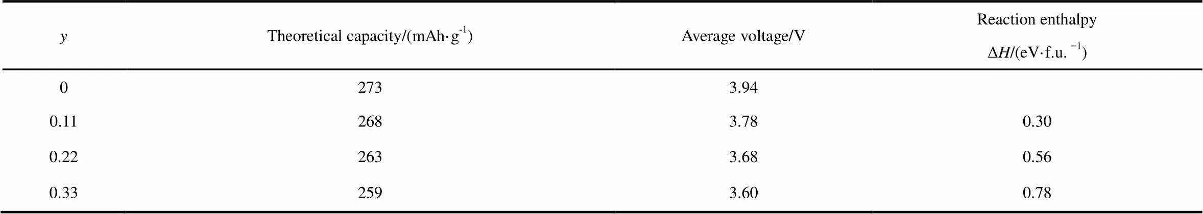
Table 1 Comparison of the theoretical capacity, the average delithiated voltage and the reaction enthalpy in LiNiO2−ySy.
3.2 Deintercalation of Li1−xNiO1.89S0.11
Firstly, we determined the delithiation sequence of different lithium sites in the configuration, as depicted in Fig.2(a). All of the lithium ions can be classified as three types: closest to the sulfur ions, next-closest to the sulfur ions, and others far away from sulfur ions. We found that the lithium ions closest to the sulfur ions are extracted prior to other lithium ions in LiNiO1.89S0.11as indicated from the calculated energy with single lithium vacancy created (see Fig.2(b)). After that, the structural stability of delithiated Li1−xNiO1.89S0.11is discussed from the perspective of thermodynamics. The formation energy of Li1-xNiO1.89S0.11is defined as:
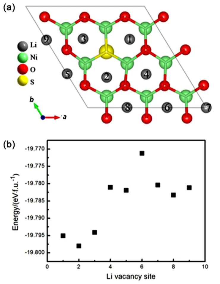
Fig.2 (a) Nine Li sites in Li layer of Li27Ni27O51S3 (LiNiO1.89S0.11), (b) the energy of system with one Li vacancy site.
The lithium atoms closest to the sulfur atom are labeled sites 1–3, the lithium atoms next-closest to the sulfur atom are labeled sites 4–6, and other lithium atoms far away from sulfur atom are labeled sites 7–9. The single Li vacancy was created by extracting the corresponding Li atom according to Fig.2(a).

ΔEf(x) = E(Li1−xNiO1.89S0.11) − xE(NiO1.89S0.11) −(1−x) E(LiNiO1.89S0.11)(2)
in which(Li1−xNiO1.89S0.11),(LiNiO1.89S0.11) and(NiO1.89S0.11) are the energies of systems withlithium delithiated, zero lithium delithiated and all lithium delithiated. Various Li-vacancy configurations in Li1−xNiO1.89S0.11were considered, and the evolution of corresponding formation energies was plotted in Fig.3(a). The negative formation energies indicate that the delithiated structure Li1−xNiO1.89S0.11is stable, rather than phase separation with a portion of LiNiO1.89S0.11and a portion of NiO1.89S0.11coexisting. The lowest formation energies points with different lithium contents are connected, forming the convex hull. The points on the convex hull represent the most stable phases in different lithium concentrations. For a comparison, the formation energies and the convex hull in Li1−xNiO2are also plotted in Fig.3(a). Interestingly, the formation energies of the convex hull in Li1−xNiO1.89S0.11are lower than that in Li1−xNiO2. It means that anion sulfur doping will enhance the structural stability during the delithiation process.
The charging voltages as a function of Li concentration in Li1−xNiO1.89S0.11are calculated using the following equation:

Fig.3 (a) Formation energies with different Li concentrations, (b) the calculated charging curves.

V = {E(LiaNiO1.89S0.11) − E(LibNiO1.89S0.11) −(b − a)E(Li)}/(b − a)e(3)
(a) LiNiO2, (b) LiNiO1.89S0.11.
3.3 Redox behavior of Li1-xNiO1.89S0.11
To further investigate sulfur redox behavior, the evolution of the average projected density of states (PDOS) during the charge process in Li1−xNiO2(Fig.S2 in Supporting Information) and Li1−xNiO1.89S0.11(Fig.S3 in Supporting Information) were calculated. In order to provide quantitative analysis, the integral of the electron density between 0 and 4 eV in conduction band was applied to study the contribution of each atom to the redox (see Fig.5). In delithiation process of Li1−xNiO2, the electron holes of nickel in conduction band increase withincreases. The electron holes of oxygen in conduction band also increases, which is attributed to the strong interaction between nickel and oxygen. Previous works also reported that the charge compensation during deintercalation was located on oxygen in LiNiO232. For Li1−xNiO1.89S0.11, the evolution of electron density of states in conduction band on nickel and oxygen are similar to Li1−xNiO2, while the electron holes on sulfur increase from 0.60 to 1.00 in initial charging process when< 0.4, and then it basically remains unchanged in the following charging process. This suggested that sulfur ions provide electrons for charge compensation during delithiation process. Moreover, we plotted the charge density differences between the LiNiO1.89S0.11and Li1−xNiO1.89S0.11(Fig.6) to determine whether sulfur is involved in redox. The charge density difference Δ1and Δ2are determined by the following definition:
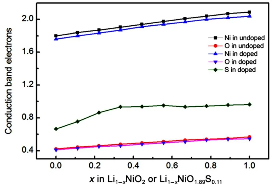
Fig.5 Evolution of integral conduction band electrons on each atom during charging process of Li1−xNiO2 and Li1−xNiO1.89S0.11.
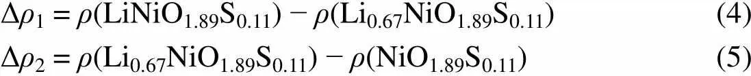
Δρ1 = ρ(LiNiO1.89S0.11) − ρ(Li0.67NiO1.89S0.11)(4) Δρ2 = ρ(Li0.67NiO1.89S0.11) − ρ(NiO1.89S0.11)(5)
In 0 << 0.33, sulfur ions provide electrons to compensate the charge during lithium extraction (Fig.6(a)), but are not involved in redox furthermore in the following process (Fig.6(b)). This is in agreement with the integral DOS analysis. Sulfur redox will result in less electron holes on oxygen at some extent, which will enhance the stability of the overcharged Li1−xNiO1.89S0.11, since we believe sulfur redox is more stable than oxygen redox due to the existence of polysulfides.
3.4 Structural stability and safety
Li1−xNiO2, especially in high delithiated phase, exhibits a poor structural and thermal stability. The structural and thermal instability are related to particle crack and phase transition. The particle crack is attributed to the lattice distortion during cycling33. The phase transition is resulted from Ni migration at elevated temperature, accompanied with oxygen gas release4. Therefore, the effect of sulfur doping on structural stability was examined from the view of the lattice distortion and thermodynamic phase transition.
It is shown previously that the structure of LiNiO1.89S0.11remains layered after sulfur substitution (see Fig.1). Sulfur doping in LiNiO2leads to the lattice parameter expansion due to the larger size of sulfur ions (see Table 2). Moreover, the/ratio, which is the characteristic of layered structure, increases after doping, and this is favorable for the structural reversibility during charging and discharging processes34. The evolution of the lattice parameters during charging in Li1−NiO1.89S0.11is plotted in Fig.7. For Li1−NiO2, lattice parametersandgradually decrease, whileincreases. But there is a turning point for parameterin= 0.8, indicating a shrinkage of the lattice alongdirection occurs at the end of charging process, which agrees well with experiments30. The latticeparameter increases with the deintercalationincreases due to the increscent repulsion between NiO6layers. The lattice shrinkage alongdirection will introduce inner strain in the structure, leading to particle micro cracks finally. After sulfur doping, the effect on the evolution ofandlattice parameters is small, whilelattice parameter is prominent. Firstly, the increasing amplitude ofis smaller than that in undoped system due to larger latticeparameter caused by sulfur substitution will reduce the repulsion between NiO6layers, and this will decrease the introduced inner strain during charging of Li1−NiO1.89S0.11. Furthermore, theparameter presents a monotonous ascending trend without any tuning points, implying that there is no lattice shrinkage at the end of charging, which will reduce particle cracks. Therefore, sulfur doping will reduce the lattice distortion and improve the structural stability during charging.
It is also known that the thermal stability of Li1−NiO2is very terrible. Here, we also investigated the thermal stability of the Li1−NiO1.89S0.11. As we know, the layered Li1−NiO2will undergo the phase transition to spinel LiNi2O4, rocksalt NiO and O2gas3,4. The phase transition requires the migration of Ni ion from the Ni layer to Li layer, passing through the intermediate tetrahedral sites33. Ni4+ion is inclined to occupy the octahedral site due to its filled2gstate, while Ni3+with an additional electron inglevel is possible to migrate to tetrahedral site35. But the migration is not easy to happen at room temperature and slightly above36. Since it requires elevated temperature to induce the migration, it is possible that the spinel LiNi2O4becomes thermodynamically unstable before it is generated kinetically from the layered phase. As temperature increases, LiNi2O4becomes unstable and will convert to LiNiO2, NiO, and O2according to the temperature evolution of ternary phase diagram of Li-Ni-O236. Hence, the phase transition reaction could be described as:

Li1–xNiO2 (layered) → (1 – x) LiNiO2 (layered) +x NiO (rocksalt) + x/2 O2(6) Li1–xNiO1.89S0.11 (layered) → (1 – x) LiNiO1.89S0.11(layered) + x NiO0.89S0.11 (rocksalt) + x/2 O2(7)
(a) Δ1, (b) Δ2. The positive isosurface is in grey. The isosurface level is 0.07. The sulfur atoms (yellow) in Li1−xNiO1.89S0.11are marked by the dotted circle. color online.

Fig.7 Evolution of lattice constants.
(a), (b)andduring delithiation of Li1–xNiO2and Li1–xNiO1.89S0.11.
We calculated the reaction enthalpies for> 0.5 according to the equation (6) or (7) (See Fig.8). The negative reaction enthalpy represents the exothermic reaction. The more the heat release, the more unstable the delithiated phase is. For Li1−NiO2, the released heat increases asincreases. It means that the delithiated phase is more and more unstable upon delithiation and will release oxygen gas finally, which is not conducive for thermal stability. However, after sulfur doping, the delithiated phase Li1−NiO1.89S0.11are more stable than Li1−NiO2due to the less heat release. Therefore, sulfur doping will enhance the thermal stability of the overcharged phase. We think the enhanced thermal stability is related to the sulfur redox. Sulfur provides a small amount of electrons to charge compensation, with less electron holes located on oxygen, thus retarding the oxygen generation. This further proves the superiority of sulfur doping in LiNiO2system.
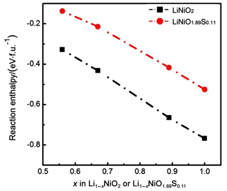
Fig.8 Reaction enthalpies of Li1−xNiO2 and Li1−xNiO1.89S0.11 with x > 0.5.
Previous study indicated that oxygen vacancy would assist TM migration in layered structures37. Given that sulfur redox will reduce the oxygen participation on charge compensation, we evaluated the doping effect on Ni migration. The delithiated supercells Li9Ni27O54(Li0.33NiO2) and Li9Ni27O51S3(Li0.33NiO1.89S0.11) were used to study Ni migration, considering that they both possess some Ni3+ions and sufficient space to allow the Ni3+ion to hop between layers. The first step of phase transition is normally regarded as Ni3+ions migrating from the octahedral sites in Ni layer to neighboring tetrahedral sites in Li layer. We compared the energy differences Δoct→tetbetween the Li9(Nitet)(Nioct)26O54[Li9(Nitet)(Nioct)26O51S3] and Li9(Nioct)27O54[Li9(Nioct)27O51S3] (See Table 3). The possible structures of Li9(Nitet)(Nioct)26O54and Li9(Nitet)(Nioct)26O51S3are shown in Fig.9. We considered three types of Ni3+with tetrahedral sites in Li9(Nitet)(Nioct)26O51S3: the tetrahedral Ni3+ion are the nearest neighbor to dopant (labeled tet-1 in Fig.9(b)), next nearest neighbor to dopant (labeled tet-2 in Fig.9(b)) and distant to dopant (labeled tet-3 in Fig.9(b)), respectively. The positive energy difference represents an endothermic character of Ni migration to tetrahedral site. The smaller the value of positive energy difference is, the more likely Ni3+ion occupys tetrahedral site. As shown in Table 3, the energy difference Δoct→tetin undoped system is about 1.24 eV, which is lower than that in all cases of sulfur doped system. Therefore, Ni3+ions have a strong preference for octahedral site after sulfur doping, which will inhibit Ni3+ion migration. From this view, sulfur doping can suppress the phase transition and enhance the structural stability.
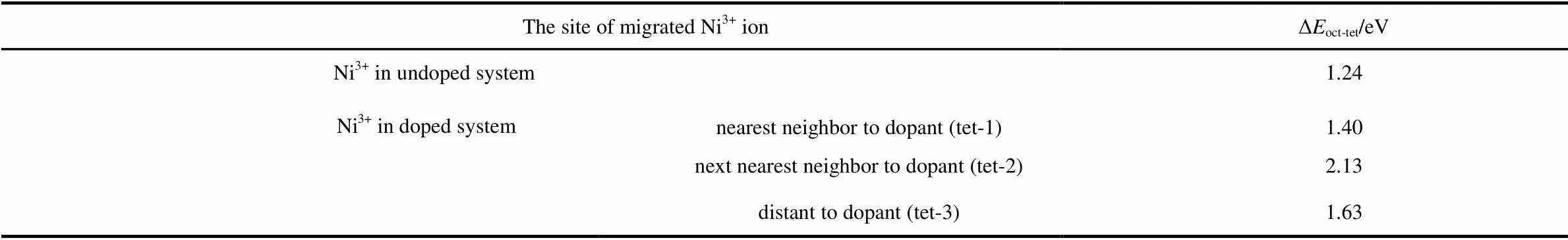
Table 3 Energy differences of the system with and without tetrahedral Ni3+ ion.
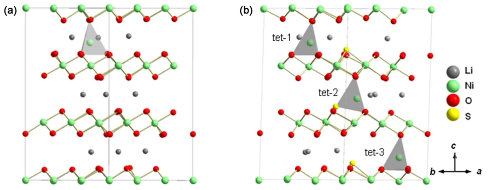
Fig.9 Configurations of Li9(Nitet)(Nioct)26O54 and Li9(Nitet)(Nioct)26O51S3.
(a) Li9(Nitet)(Nioct)26O54, (b)Li9(Nitet)(Nioct)26O51S3, the migrated Ni3+ions are divided into the nearest neighbor to dopant (tet-1), (b) next nearest neighbor to dopant (tet-2) and distant to dopant (tet-3), respectively.
4 Conclusions
The mechanism of redox chemistry in Li1−xNiO1.89S0.11during delithiation is discussed in details. Due to the introduction of sulfur, the electron density is drew closer to the Fermi energy, which results in the lowered delithiated voltage. Moreover, sulfur ions contribute electrons to charge compensation upon initial deintercalation, which will reduce electron holes on oxygen. Sulfur doping will also alleviate the change of lattice parameter upon delithiation, which is beneficial for structural stability. From the thermodynamics view, sulfur doping will suppress Ni migration and retard the oxygen evolution, which is favor of the thermodynamic stability during delithiation. This work will open up a new view in designing the Ni-rich cathode materials with multiple anions redox.
Acknowledgment: The work was carried out at National Supercomputer Center in Tianjin, and the calculations were performed on TianHe-1(A).
Supporting Information: available free of chargethe internet at http://www.whxb.pku.edu.cn.
(1) Liu, W.; Oh, P.; Liu, X.; Lee, M. J.; Cho, W.; Chae, S.; Kim, Y.; Cho, J.2015,, 4440. doi: 10.1002/anie.201409262
(2) Kim, D.; Lim, J. M.; Lim, Y. G.; Yu, J. S.; Park, M. S.; Cho, M.; Cho, K.2015,, 6450. doi: 10.1021/acs.chemmater.5b02697
(3) Wu, L.; Nam, K. W.; Wang, X.; Zhou, Y.; Zheng, J. C.; Yang, X. Q.; Zhu, Y.2011,, 3953. doi:10.1021/cm201452q
(4) Nam, K. W.; Bak, S. M.; Hu, E.; Yu, X.; Zhou, Y.; Wang, X.; Wu, L.; Zhu, Y.; Chung, K. Y.; Yang, X. Q.2013,, 1047. doi:10.1002/adfm.201200693
(5) Yang, Z. G.; Hua, W. B.; Zhang, J.; Chen, J. H.; He, F. R.; Zong, B. H.; Guo, X. D.2016,(5), 1056. [杨祖光, 滑纬博, 张 军, 陈九华, 何凤荣, 钟本和, 郭孝东. 物理化学学报, 2016,(5), 1056.] doi: 10.3866/PKU.WHXB201603092
(6) Huang, Y. Y.; Zhou, H. H.; Chen, J. T.; Gao, D. S.; Su, G. Y.2005,(7), 725. [黄友元, 周恒辉, 陈继涛, 高德淑, 苏光耀. 物理化学学报, 2005,(7), 725.] doi: 10.3866/PKU.WHXB20050706
(7) Hou, X. Q.; Jiang, W. J.; Qi, L.; Han, L. J.2007,(Supp), 40. [侯宪全, 江卫军, 其 鲁, 韩立娟. 物理化学学报, 2007,(Supp), 40.] doi: 10.3866/PKU.WHXB2007Supp10
(8) Tatsumi, K.; Sasano, Y.; Muto, S.; Yoshida, T.; Sasaki, T.; Horibuchi, K.; Takeuchi, Y.; Ukyo, Y.2008,, 045108. doi: 10.1103/PhysRevB.78.045108
(9) Woo, S. U.; Park, B. C.; Yoon, C. S.; Myung, S. T.; Prakash, J.; Sun, Y. K.2007,, A649. doi: 10.1149/1.2735916
(10) Yan, H.; Li, B.; Yu, Z.; Chu, W.; Xia, D.2017,(13), 7155. doi: 10.1021/acs.jpcc.7b01168
(11) Yue, P.; Wang, Z.; Guo, H.; Xiong, X.; Li, X.2013,, 1. doi: 10.1016/j.electacta.2013.01.018
(12) Park, S. H.; Sun, Y. K.; Park, K. S.; Nahm, K. S.; Lee, Y. S.; Yoshio, M.2002,, 1721. doi: 10.1016/S0013-4686(02)00023-3
(13) Kong, F.; Liang, C.; Longo, R. C.; Yeon, D. H.; Zheng, Y.; Park, J. H.; Doo, S. G.; Cho, K.2016,, 6942. doi: 10.1021/acs.chemmater.6b02627
(14) Li, B.; Yan, H.; Zuo, Y.; Xia, D.2017,(7), 2811. doi: 10.1021/acs.chemmater.6b04743
(15) Li, B.; Shao, R.; Yan, H.; An, L.; Zhang, B.; Wei, H.; Ma, J.; Xia, D.; Han, X.2016,, 1306. doi: 10.1002/adfm.201670054
(16) Li, B.; Yan, H.; Ma, J.; Yu, P.; Xia, D.; Huang, W.; Chu, W.; Wu, Z.2014,, 5112. doi: 10.1002/adfm.201400436
(17) Barker, J.; Kendrick, E.2011,, 6960.
(18) Lee, K. K.; Yoon, W. S.; Kim, K. B.; Lee, K. Y.; Hong, S. T.2001,, 321. doi: 10.1016/S0378-7753(01)00548-1
(19) Kresse, G.; Furthmüller, J.1996,, 11169. doi: 10.1103/PhysRevB.54.11169
(20) Kresse, G.; Joubert, D.1999,, 1758. doi: 10.1103/PhysRevB.59.1758
(21) Anisimov VI, V. I.; Zaanen, J.; Andersen, O. K.1991,, 943. doi: 10.1103/PhysRevB.44.943
(22) Zhou, F.; Cococcioni, M.; Marianetti, C. A.; Morgan, D.; Ceder, G.2004,, 35. doi: 10.1103/PhysRevB.70.235121
(23) Ma, J.; Yan, H.; Li, B.; Xia, Z.; Huang, W.; An, L.; Xia, D.2016,, 13421. doi:10.1021/acs.jpcc.6b04338
(24) Monkhorst, H. J.1976,, 5188. doi: 10.1103/PhysRevB.13.5188
(25) Chen, H.; Freeman, C. L.; Harding, J. H.2011,, 085108. doi: 10.1103/PhysRevB.84.085108
(26) Rougier, A.; Delmas, C.; Chadwick, A. V.1995,, 123. doi: 10.1016/0038-1098(95)00020-8
(27) Chung, J. H.; Proffen, T.; Shamoto, S.; Ghorayeb, A. M.; Croguennec, L.; Tian, W.; Sales, B. C.; Jin, R.; Mandrus, D.; Egami, T.2005,, 064410. doi: 10.1103/PhysRevB.71.064410
(28) Marianetti, C. A.; Morgan, D.; Ceder, G.2001,, 224304. doi: 10.1103/PhysRevB.63.224304
(29) Ouyang, C. Y.; Shi, S. Q.; Lei, M. S.2009,, 370. doi: 10.1016/j.jallcom.2008.06.123
(30) Ohzuku, T.; Ueda, A.; Nagayama, M.1993,, 1862. doi: 10.1149/1.2220730
(31) Aydinol, M. K.; Kohan, A. F.; Ceder, G.; Cho, K.; Joannopoulos, J.1997,, 1354. doi: 10.1103/PhysRevB.56.1354
(32) Uchimoto, Y.; Sawada, H.; Yao, T.2001,, 326. doi: 10.1016/S0378-7753(01)00624-3
(33) Jung, S. K.; Gwon, H.; Hong, J.; Park, K. Y.; Seo, D.-H.; Kim, H.; Hyun, J.; Yang, W.; Kang, K.2014,, 1300787. doi: 10.1002/aenm.201300787
(34) Naghash, A. R.; Lee, J. Y.2001,, 2293. doi: 10.1016/S0013-4686(01)00452-2
(35) Reed, J.; Ceder, G.2004,, 4513. doi:10.1021/cr020733x
(36) Wang, L.; Maxisch, T.; Ceder, G.2007,, 543. doi: 10.1021/cm0620943
(37) Qian, D.; Xu, B.; Chi, M.; Meng, Y. S.2014,, 14665. doi: 10.1039/c4cp01799d
阴离子硫氧化还原与Li1−xNiO2−yS的结构稳定性:第一性原理研究
鄢慧君 李 彪 蒋 宁 夏定国*
(北京大学工学院,先进电池材料理论与技术北京市重点实验室,北京 100871)
高镍层状氧化物是电动汽车高能量密度锂离子电池正极材料的首选。本文通过第一性原理计算模拟了Li1−NiO2−S材料的脱锂过程。通过GGA +计算分析了体系费米能级处的电子结构,充电过程中的氧化还原机制和热稳定性。在Li1−NiO2−S脱锂过程中,首次发现硫参与电荷补偿,抑制过渡金属的迁移,降低晶格扭曲幅度和提高体系中氧的稳定性。这种基于硫阴离子氧化还原对锂离子电池阴极材料电化学行为的调制有助于设计高稳定性的高镍正极材料。
阴离子掺杂;硫氧化还原;结构稳定性;热稳定性;过渡金属迁移
O641
10.3866/PKU.WHXB201705041
March 30, 2017;
April 20, 2017;
May 4, 2017.
. Email: dgxia@pku.edu.cn; Tel: +86-10-62767962.
The project was supported by the New Energy Project for Electric Vehicle of National Key Research and Development Program, China (2016YFB0100200) and National Natural Science Foundation of China (51671004).
国家重点研发计划“新能源汽车”重点专项(2016YFB0100200)和国家自然科学基金(51671004)资助项目
猜你喜欢
杂志排行
物理化学学报的其它文章
- Development and Validation of a Reduced Chemical Kinetic Mechanism for HCCI Engine of Biodiesel Surrogate
- Efficient Synthesis of Sulfur and Nitrogen Co-Doped Porous Carbon by Microwave-Assisted Pyrolysis of Ionic Liquid
- OL负载Cu催化剂及其催化氧化CO及乙酸乙酯性能
- Combined Effects of the Hole and Twin Boundary on the Deformation of Ag Nanowires: a Molecular Dynamics Simulation Study
- Cobalt@cobalt Carbide Supported on Nitrogen and Sulfur Co-Doped Carbon: an Efficient Non-Precious Metal Electrocatalyst for Oxygen Reduction Reaction
- S掺杂促进Fe/N/C催化剂氧还原活性的实验与理论研究