LiFePO4-Coated Li1.2Mn0.54Ni0.13Co0.13O2 as Cathode Materials with High Coulombic Efficiency and Improved Cyclability for Li-Ion Batteries
2017-12-18HELeiXUJunMinWANGYongJianZHANGChangJin
HE Lei XU Jun-Min,2, WANG Yong-Jian ZHANG Chang-Jin,3,
LiFePO4-Coated Li1.2Mn0.54Ni0.13Co0.13O2as Cathode Materials with High Coulombic Efficiency and Improved Cyclability for Li-Ion Batteries
HE Lei1XU Jun-Min1,2,*WANG Yong-Jian1ZHANG Chang-Jin1,3,*
(123)
In this work, we present a new design for a surface protective layer formed by a facile aqueous solution process in which a nano-architectured layer of LiFePO4is grown on a Li-rich cathode material, Li1.2Mn0.54Ni0.13Co0.13O2. The coated samples are then calcined at 400 or 500 °C for 5 h. The sample after calcination at 400 °C demonstrates a high initial columbic efficiency of 91.9%, a large reversible capacity of 295.0 mAh∙g‑1at 0.1(1= 300 mA∙g−1), and excellent cyclability with a capacity of 206.7 mAh∙g‑1after 100 cycles at 1. Meanwhile, voltage fading of the coated sample is effectively suppressed by protection offered by a LiFePO4coating layer. These superior electrochemical performances are attributed to the coating layer, which not only protects the Li-rich cathode material from side reaction with the electrolyte and maintains the stability of the interface structure, but also provides excess reversible capacity.
Lithium-ion battery; Lithium-rich cathode materials; LiFePO4coating; High Columbic efficiency; Cyclability
1 Introduction
Lithium-ion batteries have been widely applied in portable electronic products and are prime candidates as the power source for electric vehicles owing to their superior performance characteristics, namely, long cycle life, high energy and power densities, and no memory effect1−3. Cathode materials as the key constituent part of lithium-ion batteries play a crucial role in determining the whole battery performance. Therefore, it is of great importance to develop cathode materials with large specific capacity to fulfill the requirements for advanced lithium-ion batteries. Among the various cathode materials being developed, the lithium-rich oxides, usually denoted as Li1+x/(x+2)M(2−2x)/(x+2)Mn2x/(x+2)O2orLi2MnO3∙(1−)LiMO2(M represents the transition metal), are attracting intensive attention because of their excellent reversible capacity (~250 mAh∙g−1)4−12.
Although the Li-rich materials have the advantages of relatively high capacity and low cost, they suffer from several disadvantages, such as low initial coulombic efficiency, low rate capability and insufficient cyclability, which impose a great obstacle for their practical applications. It is well known that the particular electrochemical performance of the lithium-rich oxides including superior high capacity is mainly originated from an active process of Li2MnO3during the initial charge in the high potential range, which presents an irreversible removal of Li2O along with production of oxygen vacancies from the crystal lattice13,14. Due to this irreversible active reaction of Li2MnO3as well as the decomposition of the electrolyte in the high potential range, the lithium-rich oxides exhibit the low initial coulombic efficiency. The poor rate capability could be assigned to the obstruction of the electronic delocalization due to the introduction of Li and Mn ions in the transition metal layer and the increase of the surface resistance with cycling15−17. The poor cycling stability could correspond to the phase change from a layered to spinel structure during the subsequent cycling.
To solve these problems, many efforts have been made in the past decade to stabilize the surface and the bulk phase structures of the lithium-rich oxides. One approach is to stabilize the crystal structure by cation doping in the bulk, including Mg-doping, Sn-doping, Ti-doping and Mo-doping12,18−20. Another and more effective way is deemed as the surface modification. As demonstrated in previous reports, surface coating of carbon, metal oxide (Al2O3, Cr2O3, ZrO2, MoO3)21−24, metal fluoride (AlF3, FeF3)25,26, metal phosphate (FePO4, SmPO4)27,28, and spinel11,29can substantially improve the initial discharge capacity and greatly enhance the cyclability, possibly due to the formation of a stable solid electrolyte interphase (SEI) film to alleviate the electrolyte decomposition and retain the oxide ion vacancies in the lattice at subsequent charge-discharge cycles. For example, Wu.30have reported that LiFePO4coated LiNi0.5Mn0.3Co0.2O2exhibits a higher reversible capacity and improved cycling performance in comparison with its pristine counterpart. To our knowledge, little work has been done on Li-rich cathodes modified with this stable cathode material, namely, LiFePO4for further enhancement of Li-ion batteries performance both of initial columbic efficiency and cyclability.
In this study, we have designed a coated LiFePO4layered on Li1.2Mn0.54Ni0.13Co0.13O2a facile aqueous solution process. Subsequently, calcinations are conducted to enhance the interface interaction with polyanion penetration. Compared with the pristine sample, the LiFePO4coated Li1.2Mn0.54Ni0.13Co0.13O2shows significantly improved discharge capacity, coulombic efficiency and rate capability. The effect of the LiFePO4coating layer on the electrochemical performance of Li-rich cathode has been discussed in detail.
2 Experimental
2.1 Materials preparation
Li1.2Mn0.54Ni0.13Co0.13O2(LMNCO) was synthesized by a sol-gel method using citric acid as the chelating agent. Stoichiometric amounts of LiCOOCH3∙2H2O (Alfa Aesar, 99%), Ni(COOCH3)2∙4H2O (Alfa Aesar, > 98%), Co(COOCH3)2∙4H2O (Alfa Aesar, 98%), and Mn(COOCH3)2(Alfa Aesar, 99%) was dissolved in de-ionized water. Then the solution was added dropwisely into citric acid solution under continuous stirring. After being stirred thoroughly, the solution was heated at 80 °C and a continuous stirring was applied until a clear viscous gel was formed. The gel was dried in an oven at 80 °C to obtain the precursor powder. After heating at 480 °C in air for 5 h, the powder was ground and then calcined at 900 °C for 12 h in air. A 5% excess of lithium was used to compensate for lithium loss during the calcinations.
For preparation of 5% () LiFePO4coated LMNCO composite, the required amounts of LiCOOCH3∙2H2O and FeSO4∙7H2O (Alfa Aesar, > 99%) were dissolved in de-ionized water, followed by adding NH4H2PO4(Alfa Aesar, ≥ 98%) solution under constantly stirring. The as-prepared LMNCO was dispersed in the above solution. Then, the mixture was heated at 80°C and stirred vigorously for 5 h. After that, the suspension was laid aside for 12 h, followed by centrifuging and washing the precipitates with de-ionized water and ethanol, and drying at 80°C overnight. After mild grinding, the as-obtained powder was further heated at 400 °C (LFP-400) and 500 °C (LFP-500) for 5 h in the flowing argon. The final amounts of LiFePO4in the composites (mass fraction) for the LFP-400 and LFP-500 samples are 4.95% and 4.8%, respectively.
2.2 Morphology and structure characterizations
Powder X-ray diffraction measurement was performed on Rigaku TTR3 (Japan) with high-intensity graphite monochromatized Curadiation between 10° and 80° at a scan rate of 2 (°)∙min−1. The morphologies of the bare and coated samples were observed by Helios Nanlab 600i (Germany) scanning electron microscope (SEM) and JEM-2010 (Japan) high resolution transmission electron microscope (HRTEM). X-ray photoelectron spectroscopy of the samples was performed using Thermo ESCALAB 250 (USA) with monochromatic Alradiation.
2.3 Electrochemical measurements
The electrode materials were assembled into 2032 button cells for electrochemical measurements. A mixture of active material, carbon black (CB), and poly(vinyl difluoride) (PVDF) at a mass ratio of 75 : 15 : 10 was mixed in-methyl pyrrolidone (NMP) solution and pasted on an Al foil to prepare the working electrodes. The slurry was cast onto an Al foil and was then dried overnight in a vacuum oven at 120 °C. The loading mass of active material was adjusted to 3.6−3.9 mg. Pure lithium foil was used as a counter and reference electrode. The half-cell was composed of a cathode and a lithium metal anode separated by a Celgard 2400 porous polypropylene film separator. The electrolyte consisted of a solution of 1 mol∙L−1LiPF6in ethylenecarbonate (EC)/dimethylcarbonate (DMC)/ diethyl- carbonate (DEC) (with mass ratio of 1 : 1 : 1). The batteries assembly was carried out in a glove box (M.BRAUN MB 20G, Germany) filled with high-purity argon. The galvano- static charge and discharge tests were performed between 2.0 and 4.8 V (Li+/Li) with a NEWARE CT-3008 instrument (Shenzhen, China) at room temperature. Electrochemical impedance spectra (EIS) were measured using a Zahner Zennium (Germany) electrochemical workstation in the frequency range of 1 MHz to 1 mHz, and the cyclic voltammetry (CV) measurement was conducted in the potential range of 2−4.8 V at a scan rate of 0.1 mV∙s−1.
3 Results and discussion
Fig.1 shows the XRD patterns of the pristine and the LiFePO4coated LMNCO samples. The patterns of the pristine and LFP-400 samples can be indexed in characteristic of the O3 layered structure based on a hexagonal-NaFeO2with space group3. The weak superstructure reflections locating at around 20°−25° are corresponding to the Li+cation ordering in the transition metal layer (2/)31. Meanwhile, the separations between the adjacent peaks of (006)/(102) and (018)/(110) can be clearly observed, indicating a typical layered structure32.All the reflections are from the layered oxide without any peaks for olive phosphates, which is possibly due to the very low content of the LiFePO4layer coated on the surface of the LMNCO material. When the calcination temperature is 500 °C, the significantly weakening of superstructure reflections suggests that the structure of the solid solution is destroyed to some extent. The conductivity of the pristine sample is tested to be 0.12 S∙m−1, while the value for the LFP-400 and LFP-500 samples are 1.84 × 10⁻³S∙m−1and 0.88 × 10⁻³S∙m−1, respectively.

Fig.1 XRD patterns of the (a) Pristine, (b) LFP-400 and (c) LFP-500 samples.
SEM images of the samples are shown in Fig.2. Fig.2(a) displays that the pristine sample is composed of uniformly distributed polyhedral particles. The diameters of the particles are ~250 nm with smooth facets and sharp edges. After the surface modification with LiFePO4, there is no apparent change in grain size. A tiny difference is that the surfaces of the pristine grains are smooth, while the surfaces of the coated samples are relatively coarse. From the SEM results, we expect that the LiFePO4coating of LMNCO can effectively decrease the direct contact area between the high-voltage cathode material and the electrolyte.

Fig.2 SEM images of the (a, b) Pristine, (c, d) LFP-400 and (e, f) LFP-500 samples.
To investigate the effective coating of LiFePO4on the surfaces of Li-rich particles, we carry out HRTEM characterizations for the pristine and coated samples. For the pristine sample (Fig.3(a)), a continuous interference fringe with a distance of 0.467 nm is found until the clear grain edge, which can be indexed to the (003) plane25. On the other hand, a distinct LiFePO4layer with a thickness of 7−10 nm appears on the top surface of LFP-400 and LFP-500 samples (Fig.3(b, c)). The distances between two lattice fringes on the internal and surface of the coated samples are 0.467 nm and 0.278 nm, corresponding to (003) plane of LMNCO and (301) plane of LiFePO433, respectively. The HRTEM give clear evidences of the existence of LiFePO4coating layers on the surface of the layered oxide. Fig.3(d) shows the results of EDS analysis. The EDS analysis reveals the presence of Ni, Co, Mn, O, Sm and P in the LFP-500 sample. The calculated molar ratio of Mn : Ni : Co is 0.54 : 0.19 : 0.18, which is very close to the chemical formula of Li1.2Mn0.54Ni0.13Co0.13O2(i.e., 0.54 : 0.13 : 0.13). The calculated atomic ratio of Fe : P is ~1 from the EDS analysis. These results indicate that the actual element compositions of the pristine and LFP-500 samples are well consistent with the original experimental project.
In order to investigate the changes of surface properties and the chemical states of the elements in the surface coating layer, we perform the X-ray photoelectron spectroscopy measurements on the samples before and after the LiFePO4coating. As shown in Fig.4, the binding energy of P 2in the LFP-400 is about 133.4 eV, which is consistent with the value reported for P5+and PO43−. In the pristine sample, the P 2peaks are not detected34. There is an O 1peak at 529.35 eV in the pristine sample, which is shifted to 529.66 eV in the LFP-400 sample. The Fe 2spectrum consists of two parts, Fe 23/2and Fe 21/2, because of the spin–orbit coupling of the partially filled-orbitals (characteristic of transition metal ions). The Fe 23/2and Fe 21/2spectra are clearly seen at 711.04 eV and 724.9 eV, respectively, exhibiting the characteristic of Fe2+35,36. For Mn 2, the Mn 23/2peaks of the pristine and coated samples are located at 642.16 eV and 642.33 eV respectively, which indicates that the manganese ions are in a mixed valence of Mn4+with Mn3+37. The Ni 23/2peaks for both samples are located at 854.88 eV and 854.6 eV, respectively, while the difference between the binding energies of 21/2and 23/2levels is= 17.72 eV. Therefore, the valence state of Ni ions is +238,39. Comparatively, four signals are detected for Co 2core level. The positions of the satellite peaks and the values of, demonstrate that Co ions for both samples are in oxidation states between +2 and +340. Simultaneously considering the results of the TEM and XPS, it can be confirmed that LiFePO4has been successfully coated on the surface of the LMNCO.

Fig.3 HRTEM images of the (a) Pristine, (b) LFP-400 and (c) LFP-500 samples, (d) EDS spectra of LFP-500 sample.
The electrochemical performances of all samples are tested by galvanostatic charging and discharging in a voltage window of 2.0–4.8 V (Li+/Li) at room temperature. Fig.5(a) shows the initial charge/discharge curves of the pristine and coated samples at a low rate of 0.1(1= 300 mA∙g−1). It can be seen that the pristine sample has a long plateau that begins at ~4.5 V during the first charge. The voltage plateau on the first charge corresponds to the removal of oxygen from the Li2MnO3component, which is accompanied by the diffusion of the transition metal ions from the surface to bulk41. Compared with the pristine sample, the coated samples display almost the same charge/discharge curves except for the additional plateau in the voltage range of 2.6−2.9 V during discharge, which contributes the excess reversible capacity for the coated samples. As can be seen, the LFP-400 sample delivers a higher first discharge capacity (295.0 mAh∙g−1) than those of the pristine and LFP-500 sample, giving a high coulombic efficiency of 91.9%, whereas the pristine and LFP-500 samples deliver lower coulombic efficiency of 79.6% and 86.3%, respectively. As seen from the Table 1, the first discharge capacity and high coulombic efficiency of the LFP-400 sample are superior to the three typical LMNCO-based cathode materials12,24,29. This improvement demonstrates that the coated LiFePO4can effectively protect the layered core from erosion of electrolytes and stabilize the surface structure.

Fig.4 XPS spectra of the (a) Pristine and (b) LFP-400 sample at the P 2p, O 1s, Fe 2p, Mn 2p, Ni 2p and Co 2p corelevels.

Fig.5 (a) Charge/discharge curves of the Pristine, LFP-400 and LFP-500 samples at 0.1C; CV curves of the (b) Pristine,(c) LFP-400 and (d) LFP-500 samples at a scan rate of 0.1 mV∙s−1.
The CV curves of the pristine sample (Fig.5(b)) show two obvious oxidation peaks at ~3.9 V and ~4.6 V (Li+/Li) in the initial anodic scan, which are attributed to the reversible lithium intercalation/deintercalation in layered structure and the removal of lithium ions along with the simultaneous oxygen evolution, respectively. In the reversal scan, there is one reduction peak at ~3.2 V, which is ascribed to the Mn4+reduction to balance the charge of oxygen vacancies arising from the loss of oxygen in the first charge42. In the second scan, the CV features are significantly different from those observed in the first scan. The strongest peak at 4.6 V in the first scan disappears, indicating the irreversible reaction for Li2O removal from the crystal lattice. The CV curves of the coated samples shown in Fig.5(c, d) are similar to those of the pristine sample, except for the presence of one pair of redox peaks centered in the low voltage range of 2.6−2.9 V, which is the characteristic peak of the spinel phase. These peaks are corresponding to the reversible reaction of Mn3+/Mn4+couple, which is related to the Li+intercalation mechanism of the newly formed spinel phase component24.
When the coated mass is further became to 2% () (LFP-2) and 10% () (LFP-10). The corresponding experimental results indicate that the electrochemical properties of these two samples are not comparable with those of the LFP-400 (shown in Fig.6). For instance, the LFP-2 exhibits a maximum capacity of 263.8 mAh∙g−1and initial columbic efficiency of 80.3% at 0.1, and the LFP-10 exhibits a maximum capacity of 241.6 mAh∙g−1and initial columbic efficiency of 80.1%. These are both smaller than the LFP-400 sample, so we deem that the best coated amount is 5% ().
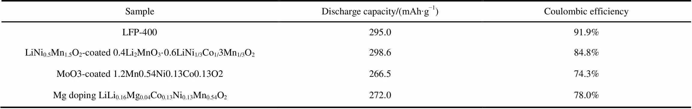
Table 1 Comparison of LFP-400 with some typical LMNCO-based materials in electrochemical performance.

Fig.6 Charge/discharge curves of the LFP-2, LFP-400 and LFP-10 samples at 0.1C.
The present work has provided evidence that high-rate discharge capacities could be achieved by LiFePO4coating on lithium-rich materials. Fig.7 shows a continuous cycling result at incremental rates from 0.1to 10then recovering back to 0.1. As can be seen, the LFP-400 sample exhibits the best rate performance among all samples, especially at 10. Such contrast observation might be related to the increasing the electrode/electrolyte contact area which may generate higher diffusion capability at an extremely high rate.
It is generally known that voltage fading is a major issue of the Li-rich layered cathode materials43. The voltage fading could be caused by the deterioration of the electrode/electrolyte interface and the structure transforms from layered to spinel-like due to Mn ions migration. Fig.8 shows the voltage fading of the pristine and coated samples from the 10th cycle to the 100th cycle at 1rate in the voltage of 2.0−4.8 V. It is clear that, when the cycling number increases, the charge voltage increase to higher plateaus, meanwhile, the discharge voltage drop to lower plateaus for all samples. This indicates the enlargement of polarization. Serious voltage fading with cycling is observed in the pristine sample, owing to the continuous undesired layered-to-spinel phase transformation. However, the voltage fading of coated samples effectively slowed down, especially for the LFP-400 sample. Therefore, the LiFePO4coating layer is more beneficial for reducing the speed of voltage fading.

Fig.7 Rate performances of the Pristine, LFP-400 and LFP-500 samples at various charge/discharge rates.
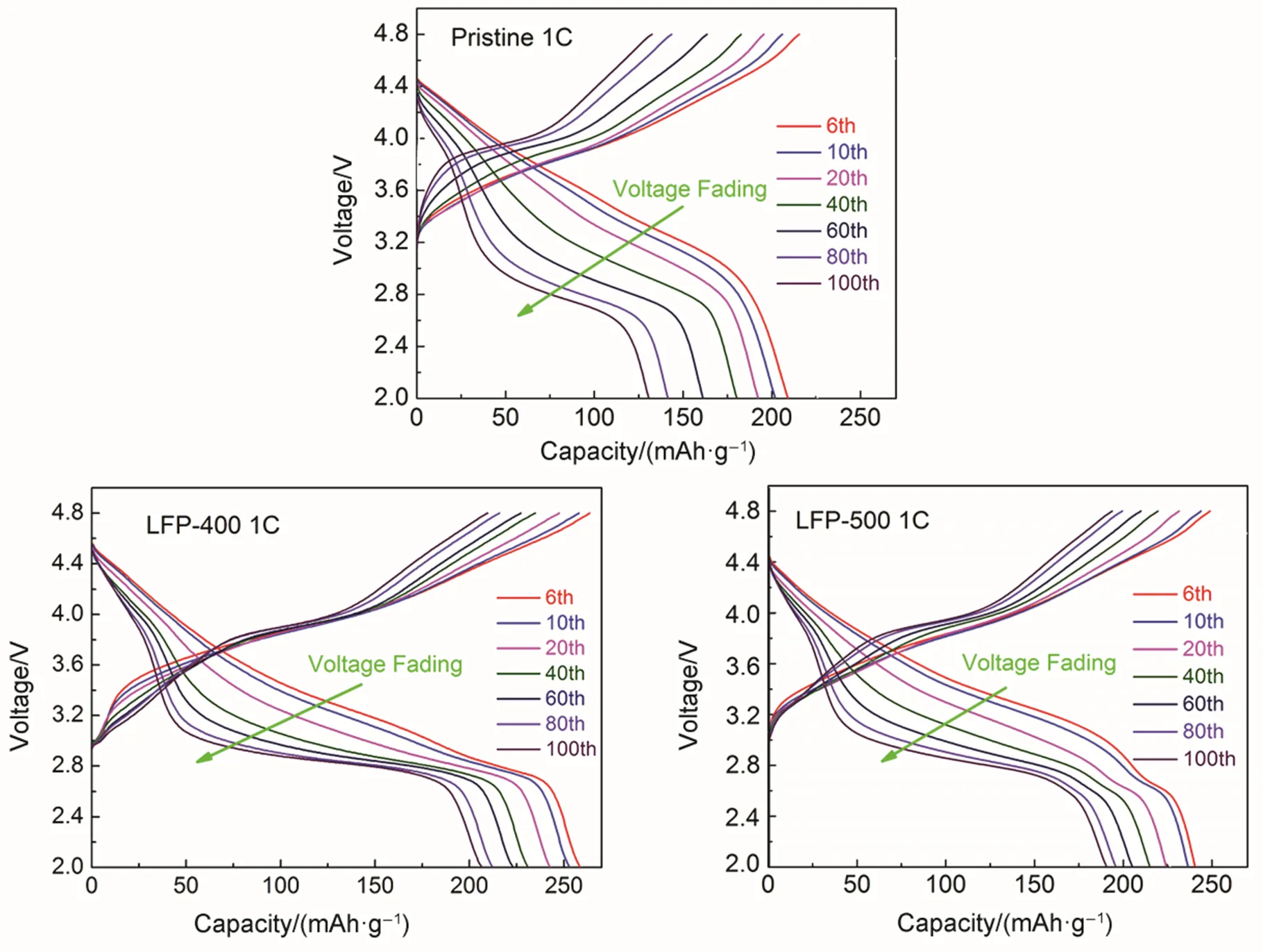
Fig.8 Voltage profiles from galvanostatic cycling of the Pristine, LFP-400 and LFP-500 samples during different cycles at 1C rate in the potential range of 2.0–4.8 V.
The cycle performances of the pristine and coated samples are evaluated at 1between 2.0 and 4.8 V. As shown in Fig.9(a), both of the coated samples deliver higher discharge capacity than the pristine sample. After 100 cycles, the LFP-400 sample exhibits a discharge capacity of 206.7 mAh∙g−1, whereas the pristine and LFP-500 samples decay to 130.7 and 190.6 mAh∙g−1. The interface layer with strong interaction can protect the cathode surface from further HF corrosion, which is favorable for ensuring the good cycle stability. To investigate the fast-charging ability, tests based on 5charge/discharge are conducted on the pristine and coated samples (Fig.9(b)). Fast extraction/insertion of Li+at high rates damages the fragile structure of pristine LMNCO, resulting in the obvious capacity fade on cycling26. Most surprisingly, the discharge capacity of the LFP-400 sample is 201.8 mAh∙g−1and can retain 183.8 mAh∙g−1after 50 cycles, while the corresponding discharge capacities of the LFP-500 sample are 121.1 and 168.1 mAh∙g−1, respectively. However, the pristine sample can only deliver a discharge capacity of 151 mAh∙g−1after 50 cycles. This superior reversible capacity and good cycling stability at high rates for the LFP-400 and LFP-500 are attributed to the fast Li+diffusion rate and structural features from the LiFePO4protective layer.

Fig.9 Cycling performances of the Pristine, LFP-400 and LFP-500 samples cycled at 1C (a) and 5C (b) between the voltage limits of 2.0−4.8 V.

Fig.10 Electrochemical impedance spectra (EIS) of the Pristine, LFP-400 and LFP-500 samples at a charge state of 4.1 V after 50 cycle in the frequency range of 1 MHz to 1 mHz.
Electrochemical impedance spectroscopy (EIS) spectra are measured for the pristine and coated samples after 50 charge-discharge cycles at 1in order to find out the underlying reason of the improvement in high-rate capability. Before the EIS measurements, all samples are charged to 4.1 V at 1rate to reach an identical status. As shown in Fig.10, both Nyquist plots are composed of two semicircles and one slope, which can be explained by using the equivalent circuits (the insets in Fig.10): the first semicircle (at high frequency region) is ascribed to the lithium ion diffusion resistance through the surface layer (f), the second semicircle (at medium-to-low frequency region) is assigned to the charge transfer resistance (ct) at electrolyte-electrode interfacial, and the slope at the low frequency region is attributed to lithium ion diffusion Warburg impedance (w) in the bulk material24,44. All EIS spectra are fitted using the equivalent circuit shown the inset of Fig.10. The fitting results offandctfor all samples are tabulated in Table 2. It is obvious that the value offfor pristine sample is beyond 28.7 Ω, while those for the LFP-400 and LFP-500 samples are 7.0 and 7.7 Ω, respectively. For thect, it is about 125.7 Ω for the pristine sample, much larger than the LiFePO4coated samples. Especially for the LFP-400 sample, the value ofctis only 63.2 Ω. Among the three samples, the LFP-400 sample exhibits the lowestfandctvalues. This means that the side reaction between cathode electrode and electrolyte is markedly suppressed by LiFePO4coating layer. The lowerfandctvalues could accelerate the Li+diffusion rate at the electrode/electrolyte interface, and then are beneficial to enhancing the electrochemical properties of LMNCO during cycling45. Therefore, it is reasonable to conclude that the improvement of the electrochemical reaction activity and ion diffusion are responsible for the high coulombic efficiency, good cycle stability and remarkable fast-charging ability of the LFP-400 sample.
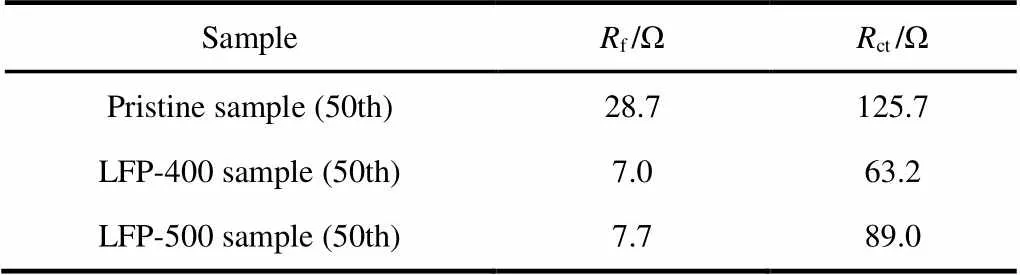
Table 2 Fitted impedance parameters of the Pristine, LFP-400 and LFP-500 samples.
4 Conclusions
In summary, we have successfully prepared LiFePO4- coated Li1.2Mn0.54Ni0.13Co0.13O2by a facile aqueous solution method. The LFP-400 sample exhibits a high coulombic efficiency, high reversible capacity, good cycle stability and small voltage fading, which may eventually lead to advanced Lithium-ion batteries that meet the requirements of electric vehicles and renewable energy storage. Such an enhanced performance is associated with the active surface protective layer LiFePO4. The same strategy adopted in this work could also be extended to other high energy cathode materials with either high potential or high capacity.
(1) Armstrong, A. R.; Lyness, C.; Panchmatia, P. M.; Islam, M. S.; Bruce, P. G.. 2011,, 223. doi:10.1038/nmat2967
(2) Chiang, Y. M.2010,, 1485. doi: 10.1126/science.1198591
(3) Gu, M.; Belharouak, I.; Genc, A.; Wang, Z.; Wang, D.; Amine, K.; Gao, F.; Zhou, G.; Thevuthasan, S.; Baer, D. R.; Zhang, J. G.; Browning, N. D.; Liu, J., Wang, C.. 2012,, 5186.10.1021/nl302249v
(4) Johnson, C. S.; Kim, J. S.; Lefief, C.; Li, N.; Vaughey, J. T.. 2004,, 1085. doi: 10.1016/j.elecom.2004.08.002
(5) Wei,G. Z.; Xia, L.; Ke, F. S.; Huang, L.; Li, J. T.; Wang, Z. X.; Zhou, Z. Y.; Sun, S. G.2010,, 4364. doi: 10.1002/adma.201001578
(6) Yu, H. J.; Zhou, H. S.. 2012,, 15507. doi: 10.1039/c2jm33484d
(7) Kang, S. H.; Sun, Y. K.; Amine, K.. 2003,, A183. doi: 10.1149/1.1594411
(8) Zhu, Z. Y.; Zhu, L. W.2014,, 178. doi: 10.1016/j.jpowsour.2014.01.068
(9) Oh, P.; Ko, M.; Myeong, S.; Kim, Y.; Cho, J.. 2014,, 1400631. doi: 10.1002/aenm.201470087
(10) He, F.; Wang, X. Q.; Du, C. Q.; Baker, A. P.; Wu, J. W.; Zhang, X. H.2015,, 484. doi: 10.1016/j.electacta.2014.11.139
(11) Yang, C.; Zhang, Q.; Ding, W. X.; Zang, J.; Lei, M.; Zheng, M. S.; Dong, Q. F.2015,, 7554. doi: 10.1039/c5ta00009b
(12) Jin, X.; Xu, Q. J.; Liu, H. M.; Yuan, X. L.; Xia, Y. Y.2014,, 19. doi: 10.1016/j.electacta.2014.05.043
(13) Armstrong, A. R.; Holzapfel, M.; Novak, P.; Johnson, C. S.; Kang, S. H.; Thackeray, M. M.; Bruce, P. G.2006,, 8694.10.1021/ja062027+
(14) Lu, Z.; Dahn, J. R.2002,, A815. doi: 10.1149/1.1480014
(15) Xu, B.; Fell, C. R.; Chi, M.; Meng, Y. S.. 2011,, 2223. doi: 10.1039/C1EE01131F
(16) Cong, L.; Lei, K. X.; Wang, J. W.; Wang, J. B.; Meng, H. J.; Chen. F. Y.; Chen, J.2016,, 2216. [丛 亮, 雷凯翔, 王纪伟, 王建斌, 孟焕菊, 程方益, 陈 军. 科学通报, 2016,, 2216.] doi: 10. 1360/N972016-00325
(17) Yabuuchi, N.; Yoshii, K.; Myung, S. T.; Nakai, I.; Komaba, S.. 2011,, 4404. doi:10.1021/ja108588y
(18) Zhao, Y. J.; Xia, M. H.; Hu, X. S.; Zhao, Z. K.; Wang, Y.; Lv, Z.2015,, 1167. doi: 10.1016/j.electacta.2015.05.068
(19) Yamamoto, S.; Noguchi, H.; Zhao, W.2015,, 76. doi: 10.1016/j.jpowsour.2014.12.038
(20) Du, J. Y.; Shan, Z. Q.; Zhu, K. L.; Liu, X. Y.; Tian, J. H.; Du, H. Y.. 2015,,1037. doi: 10.1007/s10008-014-2706-6
(21) Kang, S. F.; Li, B.; Qin, H. F.; Fang, Y.; Li, X.; Wang, Y. G.. 2015,, 525. doi: 10.1007/s10008-014-2585-x
(22) Li, B.; Li, C.; Cai, J. J.; Zhao, J. B.2015,, 21290. doi: 10.1039/c5ta06387f
(23) Lee, H. J.; Park, Y. J.2013,, 222. doi: 10.1016/j.jpowsour.2013.01.154
(24) Wang, C. L.; Zhou, F.; Chen, K. M.; Kong J. Z.; Jiang, Y. X.; Yan, G. Z.; Li J. X.; Yu, C.; Tang, W. P.2015,, 1171. doi: 10.1016/j.electacta.2015.07.167
(25) Sun Y. K.; Lee, M. J.; Yoon, C. S.; Hassoun, J.; Amine, K.; Scrosati, B.2012,, 1192. doi: 10.1002/adma.201104106
(26) Zhao, T. L.; Li, L.; Chen, R. J.; Wu, H. M.; Zhang, X. X.; Chen, S.; Xie, M.; Wu, F.; Lu, J.; Amine, K.2015,, 164. doi: 10.1016/j.nanoen.2015.04.013
(27) Wang, Z. Y.; Liu, E. Z.; He, C. N.; Shi, C. S.; Li, J. J.; Zhao, N. Q.2013,, 25. doi: 10.1016/j.jpowsour.2013.02.022
(28) He, L.; Xu, J. M; Han, T.; Han, H.; Wang, Y. J.; Yang, J.; Wang, J. R.; Zhu, W. K.; Zhang, C. J.; Zhang, Y. H.2017,, 5267. doi: 10.1016/j.ceramint.2017.01.052
(29) Chen, Y. F.; Xie,K.;Zheng, C. M.;Ma, Z. Y.;Chen, Z. X.2014,, 16888. doi: 10.1021/am504412n
(30) Wu, Z. Z.; Ji, S. P.; Liu, T. C.; Duan, Y. D.; Xiao, S.; Lin, Y.; Xu, K.; Pan, F.. 2016,, 6357. doi: 10.1021/acs.nanolett.6b02742
(31) Shi, S. J.; Tu, J. P.; Zhang, Y. D.; Zhang, Y. J.; Gu, C. D.; Wang, X. L.2013,, 828. doi: 10.1016/j.electacta.2013.08.002
(32) Liu, J.; Manthiram, A.. 2010,, 3961. doi: 10.1039/b925711j
(33) Gao, H. Y.; Zhe, H.; Zhang, K. Cheng, F. Y.; Chen, J.. 2013,, 3040. doi: 10.1039/c3cc40565f
(34) Wu, Y.; Murugan, A. V.; Manthiram, A.. 2008,, A635. doi: 10.1149/1.2948350
(35) Bhuvaneswari, M. S.; Bramnik, N. N.; Ensling, D.; Ehrenberg, H.; Jaegermann, W.2008,, 553. doi: 10.1016/j.jpowsour.2008.01.090
(36) Li, X. L.; Jin, H. C.; Liu, S.; Xin, S.; Meng, Y.; Chen, J. J.2015,, 116.10.1039/C4TA04358H
(37) Ivanova, S.; Zhecheva, E.; Stoyanova, R.; Nihtianova, D.; Wegner, S.; Tzvetkova, P.; Simova, S.2011,, 25170.10.1021/jp208976h
(38) Kang, S. H.; Kim, J.; Stoll, M. E.; Abraham, D.; Sun, Y. K.; Amine, K.2002,, 41. doi: 10.1016/S0378-7753(02)00360-9
(39) Yu, C.; Li, G.; Guan, X.; Zheng, J.; Li, L.; Chen, T.2012,, 283. doi: 10.1016/j.electacta.2012.06.084
(40) Dahéron, L.; Dedryvère, R.; Martinez, H.; Ménétrier, M.; Denage, C.; Delmas, C.; Gonbeau, D. Chem. Mater. 2008, 20, 583. doi: 10.1021/cm702546s
(41) Kim, J. M.; Kumagai, N.; Chung, H. T.2006,, A494. doi: 10.1149/1.2336988
(42) Wang, Q. Y.; Liu, J.; Murugan, A. V.; Manthiram, A.2009,, 4965. doi: 10.1039/b823506f
(43) Croy, J. R.; Kim, D.; Balasubramanian, M.; Gallagher, K.; Kang, S. H.; Thackeray, M. M.. 2012,, A781. doi: 10.1149/2.080206jes
(44) He, W.; Yuan, D. D.; Qian, J. F.; Ai X. P.; Yang, H. X.; Cao, Y. L.2013,, 11397. doi: 10.1039/c3ta12296d
(45) Kim, H. S.; Kong, M. Z.; Kim, K.; Kim, I. J.; Gu, H. B.2007,, 917. doi: 10.1016/j.jpowsour.2007.06.028
LiFePO4包覆的Li1.2Mn0.54Ni0.13Co0.13O2锂离子电池正极材料:增强的库伦效率和循环性能
何 磊1徐俊敏1,2,*王永建1张昌锦1,3,*
(1中国科学院强磁场科学中心,合肥 230031;2郑州大学物理工程学院,材料物理教育部重点实验室,郑州 450052;3南京大学人工微结构科学与技术协同创新中心,南京 210093)
采用简单水溶液法制备LiFePO4包覆的Li1.2Mn0.54Ni0.13Co0.13O2富锂正极材料,包覆后的材料分别经过400 °C或500 °C煅烧处理5 h。测试结果显示,400 °C煅烧处理的包覆样品在0.1(1= 300 mA∙g−1)电流密度下充放电时,首次库仑效率可以高达91.9%,同时,首次放电比容量可达到295.0 mAh∙g‑1。此外,该包覆样品还具有良好的循环性能,在1电流密度下循环100次放电比容量仍可保持在206.7 mAh∙g‑1。进一步的研究发现LiFePO4的包覆不仅可以提高Li1.2Mn0.54Ni0.13Co0.13O2富锂材料的首次库仑效率和循环稳定性能,而且还能够有效抑制材料在充放电过程中的电压衰减。上述电化学性能的有效提升主要归因于LiFePO4包覆层可以阻碍Li1.2Mn0.54Ni0.13Co0.13O2富锂材料与电解液之间的直接接触,减少副反应的发生,增强材料表面的结构稳定性,同时还可以为富锂材料提供额外的可逆容量。
锂离子电池;富锂正极材料;磷酸铁锂包覆;高库仑效率;循环性能
O646;O614;O469
10.3866/PKU.WHXB201704145
March 2, 2017;
March 27, 2017;
April 14, 2017.
Corresponding authors.XU Jun-Min, Email: junminxu@zzu.edu.cn; Tel: +86-371-67767670. ZHANG Chang-Jin, Email:zhangcj@hmfl.ac.cn;
Tel: +86-551-65595655.
The project was supported by the Scientific Research Grant of Hefei Science Center of Chinese Academy of Sciences (2015SRG-HSC025) and National Natural Science Foundation of China (U1532267, 11504379).
中国科学院合肥科学中心科学研究项目(2015SRG-HSC025)和国家自然科学基金(U1532267, U11504379)资助