Plasma Treatment Enhanced Magnetic Properties in Manganese Doped Titanium Nitride Thin Films
2017-09-03DanLiLingmingXuShuweiLiXunZhou
Dan Li,Ling-ming Xu,Shu-wei Li,Xun Zhou
a.School of Physics&Electronics,Guizhou Normal University,Guiyang 550001,China
b.State Key Laboratory of Optoelectronic Materials and Technologies,School of Materials Science and Engineering,Sun Yat-sen University,Guangzhou 512075,China
Plasma Treatment Enhanced Magnetic Properties in Manganese Doped Titanium Nitride Thin Films
Dan Lia,b,Ling-ming Xub,Shu-wei Lib,Xun Zhoua∗
a.School of Physics&Electronics,Guizhou Normal University,Guiyang 550001,China
b.State Key Laboratory of Optoelectronic Materials and Technologies,School of Materials Science and Engineering,Sun Yat-sen University,Guangzhou 512075,China
The ferromagnetic manganese doped TiN films were grown by plasma assisted molecular beam epitaxy on MgO(001)substrates.The nitrogen concentration and the ratio of manganese at Ti lattice sites increase after the plasma annealing post treatment.TiN(002)peak shifts toward low angle direction and TiN(111)peak disappears after the post treatment. The lattice expansion and peak shift are mainly ascribed to the reduction of nitrogen vacancies in films.The magnetism was suppressed in as-prepared sample due to the pinning effect of the nitrogen vacancies at defect sites or interface.The magnetism can be activated by the plasma implantation along with nitrogen vacancies reduce.The decrease of nitrogen vacancies leads to the enhancement of ferromagnetism.
Epitaxial growth,Magnetic materials,Thin films,Solar energy materials
I.INTRODUCTION
The titanium nitride(TiN)is a potential functional material due to their metallic and covalent binding characteristics.It exhibits excellent compatibility with semiconductor industry and traditional silicon devices as diffusion barrier[1,2],Ohmic contact layer[3,4], gate electrodes[5],sensor material[6],spin electron materials[7],and transparent conductive layer in photovoltaic industry[8,9].TiN is of potential application for silicon and germanium semiconductor devices as electrode materials due to it low Ohmic contact and low Schottky barrier[4,10].Efforts have been made to search suitable materials for both spin injection and spin combination of traditional semiconductor technology[11,12].The materials with spin-dependent characteristics,electrical performance,and magnetic properties are strongly needed[13].Manganese(Mn)doped TiN thin films grown by plasma assisted molecular beam epitaxy(PAMBE)present even lower Schottky barrier height and remarkable magnetic behaviors[14]. Some studies emphasize the role of nitrogen on regulating the concentration of nitrogen vacancies to enhance its physical characteristics and electric behaviors.The nitrogen ions and the doped transition metal atoms tend to cluster together,which induces the large spin split acceptor in transition metal doped ZnO and TiO2,etc. [15,16].The sensing performance of TiN can be enhanced by adjusting of nitrogen pressure and post rapid temperature annealing[6].The nitrogen plasma treatment can reduce the nitrogen vacancies and promote the crystalline quality.Moreover,the nitrogen plasma treatment can change the magnetic properties in Mn doped GaN system[17,18].The post treatment enlarges the content of substantial component and therefore improves the magnetization finally.In this paper, we report nitrogen plasma treatment of Mn doped TiN films on MgO(001)substrates deposited by PAMBE. We study the structural and characteristic change before and after the plasma annealing treatment.
II.EXPERIMENTS
About 20 nm of Mn doped TiN films were grown in a PAMBE system(German Omicron Ltd.,Custombuilt)with a re flection high energy electron diffraction (RHEED)growth monitoring system.Post treatment was exerted on the as-prepared samples at 800◦C and radio frequency of 200 W(Oxford applied RF plasma source),and under 700 mTorr of nitrogen pressure for 10 min.All measurements were measured before and after the post treatment under similar conditions. Atomic force microscope(AFM)was used for the surface topography of films.The X-ray diffraction(XRD) and X-ray photoelectron spectroscopy(XPS)were utilized for crystalline structure and chemical state respectively.The superconducting quantum interference device(SQUID)was used to test the ferromagnetic properties under in-plane magnetic fields from−60 kOe to 60 kOe.

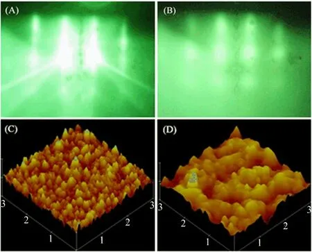
FIG.1 RHEED patterns of(A)Mg(001)substrate and (B)doped TiN on MgO(001).AFM of(C)as-prepared and (D)post-treated film.
III.RESULTS AND DISCUSSION
The evolution process of RHEED pattern demonstrates excellent crystalline quality of as-prepared samples.Clear streaky stripes of single crystal substrate accompanied with some Kikuchi lines and secondary diffraction lines could be seen from FIG.1(A).Obscure periodic bright spot array could be seen from posttreated sample as FIG.1(B)shows.The spot arrays hint that the film is single crystal even though the surface is somewhat rough,which keeps invariant before and after the post treatment.
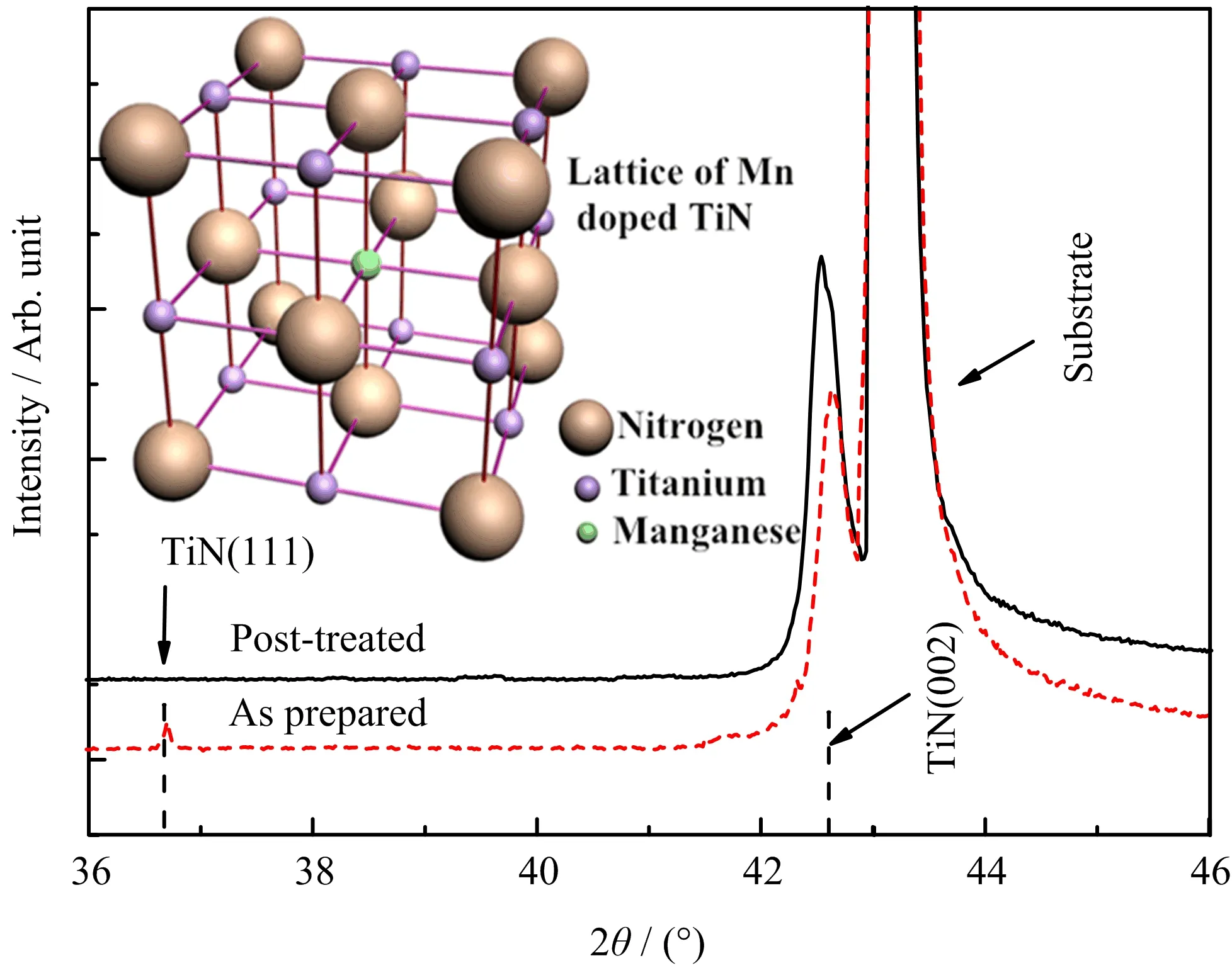
Apparently,the post-treated sample presents much smoother surface and bigger grain size according to FIG.1(C)and(D).The root mean square surface roughness is 5.435 nm for the as-prepared sample and 2.236 nm for the post-treated sample.Excepting for the surface topography change of the films,the inner structure is evidently affected by the post treatment process.A tiny peak for TiN(111)at 36.6◦emerges in the curve of as-prepared films besides the peak for substrate and the main peak for TiN(002)at 42.64◦(65♯0565 Fm-3m).The TiN(111)phase probably originates from the lattice mismatch of substrate and epitaxial layer when the baffle of Ti source is suddenly turned away.The time is too short for the resultant to grow under chemical equilibrium state at the moment when plenty of Ti atoms arrive on the surface of MgO substrate.TiN(111)phase generates at the early stage of the growth since the crystal orientation of TiN has not been de fined.The epitaxial layer deforms to match the MgO(100)substrate lattice for the sake of system energy reduction.The peak position does not completely match the standard data due to the Mn doping and nitrogen vacancies.Nitrogen vacancies generate duringthe course of thin film growth,especially in the doped cases[19].The epitaxial layer XRD deviates to high angle side due to nitrogen vacancies in as-prepared films that could lead to compression in unit cells.TiN(002) peak shifts toward low angle and TiN(111)peak disappears after the post treatment.The peak deviating to low angle side is ascribed to the reduction of nitrogen vacancies and therefore the generation of expansion in unit cells.The nitrogen ions will recruit into the lattice again and cause reorganization in lattice during this course when the films undergo post treatment.Some nitrogen ions diffuse to the film-substrate interface and repair the deformed buffer layer since the thickness of TiN is merely 20 nm.The lattice atoms at the interface get enough kinetic energy and atomic mobility at 800◦C thus enable the lattice atoms uniformly arrange according to the(100)orientation since the binding energy of(100)is higher than(111)and(110)[20].As a result,the TiN(111)orientated unit cells and corresponding XRD peak vanish under the driving force of Gibbs free energy while sample undergo post treatment.

FIG.2 XRD of as-prepared and post-treated Mn doped TiN,inset is the lattice structure.
The conduction band of TiN has essentially a titanium 3d character and shows 3d to 4s orbital hybridization character.In doped case,the Mn donates its one 3d and two 4s electrons to nitrogen for bonding.In asprepared sample(FIG.3(a)),the overlapped Ti 2p3/2peak is located at 455.0 eV,which is close to reported data 454.8 eV.The peak can be decomposed into two peaks of 454.85 and 459.1 eV,respectively,which is identi fied as Ti−N[21]and Ti−O−N[22].The Ti−N peak shifts slightly to the low binding energy side owing to the existence of nitrogen vacancies[23].The Ti−N peak shifts from 454.8 eV to 455.6 eV and the peak of the sum shifts from 455.0 eV to 455.9 eV,while the Ti−O−N peak shifts from 456.0 eV to 456.4 eV,which indicates that more Ti shift to higher value and vacancies decrease correspondingly.The Ti 2p3/2peak ispromoted to a higher value after the post treatment as FIG.3(b)shows.However,the spectra also present even stronger Ti−O−N peak because the samples are not in situ post treated.Some absorbed oxygen atoms will be collided into the lattice of TiN,leading to the generation of Ti−O−N.The even clear Mn2+peak indicates the further implantation of Mn element into the sites of titanium(FIG.3(c))[14].XPS measurements show that the atomic molar ratio of Ti:Mn:N in as-prepared films is about 0.9:0.1:0.9 while the atomic molar ratio is about 0.9:0.1:0.98 in post-treated film.One fact can be veri fied that the plasma treatment can reduce N vacancies according to measured data since the content of nitrogen in post-treated samples increases from 0.9 to 0.98 even though the XPS is not a precise measurement method.This might be a further evidence that the production of vacancies is suppressed by nitrogen plasma annealing[18].

FIG.3 The XPS spectra of Ti 2p of(a)as-prepared sample and(b)post-treated sample,(c)Mn 2p of post-treated sample.
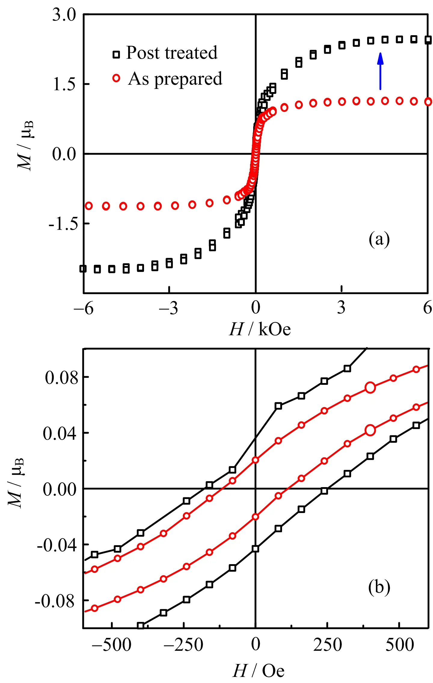
The magnetic moment is plotted as a function of magnetic field strength at room temperature in FIG.4.Experimental data show that Mn doping into TiN lattice can generate ferromagnetism.The saturation moment of as-prepared samples is much lower than theoretical data 2−3µBper Mn[24].The magnetism is suppressed because the conduction band is pinned near the Fermi level due to the nitrogen vacancies at defect sites or interface[4,25,26].In another words,the Mn ions in asprepared samples are suppressed to a low spin state for about 1µBper Mn[14].However,the ferromagnetism of Mn doped TiN is obviously seen from the M-H curve even though the existence of suppression effects.The nitrogen atoms are seriously insufficient under very high vacuum,and therefore the generation of nitrogen vacancies is inevitable[27].The ferromagnetic ground state and the local magnetic moment abruptly decrease with nitrogen vacancies according to first-principles study [28].When the as-prepared samples are exposed to the nitrogen plasma at high temperature,Mn atoms can diffuse in the lattice through nitrogen vacancies during the course[29].The concentration of Mn that occupies the titanium sites can signi ficantly be increased as a result due to higher temperature and higher plasma energy.The diffusion interstitial Mn atoms are suppressed and further reduce the possible Mn−N anti-ferromagnetic compounds.The additional nitrogen ions are recruited into the TiN lattice until the nitrogen vacancies are mostly eliminated.The increase of Mn concentration at lattice sites can heighten the value of saturated magnetic moment[30].On the other hand,the elimination of nitrogen vacancies attenuates the pinning effect[31]. Compared with the as-prepared samples,ferromagnetic curve with much higher saturation magnetic moment of 2.5µBper Mn was obtained,which is consistent with theoretic calculation[32].

FIG.4 Magnetism of(a)as-prepared and(b)post-treated samples.
IV.CONCLUSION
In summary,the morphology is optimized on the surface,and lattice is reincorporated inner the samples during the post plasma annealing treatment.The shift of Ti 2p peak to higher energy direction indicates more Ti atoms bond at higher value since the more oxidative atoms are recruited into lattice.The concentration of Mn atoms that occupy at titanium sites ascends and the amount of nitrogen vacancies descends after the plasma annealing treatment.The magnetism is suppressed in as-prepared sample due to the pinning effect of the nitrogen vacancies at defect sites or interface.The nitrogen plasma anneal treatment may reduce nitrogen vacancies and therefore attenuate the pinning effect.The magnetism is activated by the plasma implantation of nitrogen ions into the lattice along with nitrogen vacancies reduce.The concentration increase of Mn that is located at Ti sites as well as the concentration decrease of nitrogen vacancies would evidently lead to the enhancement of ferromagnetism.
V.ACKNOWLEDGMENTS
This work is supported by the Science and Technology Cooperation Plan of Guizhou Province(JLKS[2013]15),the 2012 Doctor Foundation of Guizhou Normal University of China(Xun Zhou)Scholars ofMinistryofEducation ofChina,Ph.D.Programs Foundation of Ministry of Education of China (No.20120171120011),the Open Fund of the State Key Laboratory on Integrated Optoelectronics of Jilin University(No.IOKL2013KF14),the National Natural Science Foundation of China(No.61273310).
[1]M.Wittmerand H.Melchior,Thin Solid Films 93,397 (1982).
[2]H.O.Pierson,Handbook of Refractory Carbides and Nitrides,William Andrew:Elsevierence,(1996).
[3]M.Wittmer,J.Vac.Sci.Technol.A 3,1797(1985).
[4]H.D.Wu,W.Huang,W.F.Lu,R.F.Tang,C.Li,H. K.Lai,S.Y.Chen,and C.L.Xue,Appl.Surf.Sci.284, 877(2013).
[5]N.Ramanuja,R.A.Levy,S.N.Dharmadhikari,E. Ramos,C.W.Pearce,S.C.Menasian,P.C.Schamberger,and C.C.Collins,Mater.Lett.57,261(2002).
[6]C.Ren,C.M.Yang,C.Lyu,C.Y.Hsu,T.C.Chen, H.C.Wang,H.Yang,W.T.Lin,P.C.Juan,C.H. Huang,D.G.Pijanowska,J.C.Wang,and J.R.Tsai, Vacuum 118,113(2015).
[7]A.Sugihara,S.Osaki,and R.Nakatani,J.Jpn.Inst. Met.Mater.77,398(2013).
[8]Y.Nishio,T.Yamaguchi,K.Nishio,and S.Hayase,J. Appl.Electrochem.46,551(2016).
[9]G.Q.Wang and S.M.Liu,Mater.Lett.161,294 (2015).
[10]J.Xing,H.Y.Hao,and Z.Y.Zheng,Opt.Adv.Mat. 5,1174(2011).
[11]V.V.Osipov and A.M.Bratkovski,Spin Injection Devices 7164181(2005).
[12]P.Borisov,A.Hochstrat,V.V.Shvartsman,W.Kleemann,and P.M.Hauck,Integr.Ferroelectr.99,69 (2008).
[13]S.A.Wolf,D.D.Awschalom,R.A.Buhrman,J. M.Daughton,S.von Moln´ar,M.L.Roukes,A.Y. Chtchelkanova,and D.M.Treger,Science 294,1488 (2001).
[14]S.X.Wu,Y.Q.Xia,X.L.Yu,Y.J.Liu,and S.W.Li, J.Appl.Phys.102,063911(2007).
[15]K.R.Kittilstved,W.K.Liu,and D.R.Gamelin,Nat. Mater.5,291(2006).
[16]S.Q.Ren,H.W.Qin,J.P.Bu,G.C.Zhu,J.H.Xie, and J.F.Hu,Appl.Phys.Lett.107,062404(2015).
[17]J.M.Baik,Y.Shon,T.W.Kang,and J.L.Lee,Appl. Phys.Lett.89,152113(2006).
[18]J.M.Baik,Y.Shon,T.W.Kang,and J.L.Lee,Appl. Phys.Lett.84,1120(2004).
[19]L.Miao,S.Tanemura,H.Watanabe,Y.Mori,K. Kaneko,and S.Toh,J.Cryst.Growth 260,118(2004).
[20]L.A.Zhang,S.Tong,H.N.Liu,Y.L.Li,and Z.Wang, Mater.Lett.171,304(2016).
[21]I.V.Blinkov,A.O.Volkhonskii,and Y.V.Konyukhov, Russ.Metall.2012,599(2012).
[22]S.Tanemura,L.Miao,Y.Kajino,M.Tanemura,S.Toh, K.Kaneko,and Y.Mori,Jpn.J.Appl.Phys.46,356 (2007).
[23]N.Jiang,H.J.Zhang,S.N.Bao,Y.G.Shen,and Z. F.Zhou,Phys.B 352,118(2004).
[24]A.Herwadkar and W.R.L.Lambrecht,Phys.Rev.B 72,235207(2005).
[25]X.K.Ning,Z.J.Wang,and Z.D.Zhang,Sci.Rep.5, 8460(2015).
[26]K.Yamane,K.Hamaya,Y.Ando,Y.Enomoto,K.Yamamoto,T.Sadoh,and M.Miyao,Appl.Phys.Lett. 96,162104(2010).
[27]T.Priem,B.Beuneu,C.H.de Novion,R.Caudron,F. Solal,and A.N.Christensen,Solid State Commun.63, 929(1987).
[28]V.V.Bannikov,I.R.Shein,N.I.Medvedeva,and A. L.Ivanovskii,J.Magn.Magn.Mater.321,3624(2009).
[29]M.B.Haider,C.Constantin,H.Al-Brithen,H.Q. Yang,E.Trifan,D.Ingram,A.R.Smith,C.V.Kelly, and Y.Ijiri,J.Appl.Phys.93,5274(2003).
[30]J.M.Baik,Y.Shon,T.W.Kang,and J.L.Lee,Appl. Phys.Lett.87,042105(2005).
[31]S.G.Jeong,H.Y.Park,M.H.Lim,W.S.Jung,H.Y. Yu,Y.Roh,and J.H.Park,Org.Electron.13,1511 (2012).
[32]S.X.Wu,Y.Q.Xia,X.L.Yu,Y.J.Liu,and S.W.Li, J.Appl.Phys.102,063911(2007).
ceived on March 20,2017;Accepted on June 26,2017)
∗Author to whom correspondence should be addressed.E-mail: hbkfy@gznu.edu.cn
杂志排行
CHINESE JOURNAL OF CHEMICAL PHYSICS的其它文章
- γ-Ray Irradiation-Derived MnO/rGO Composites for High Performance Lithium Ion Batteries
- Identi fication of Superoxide O2−during Thermal Decomposition of Molten KNO3-NaNO2-NaNO3Salt by Electron Paramagnetic Resonance and UV-Vis Absorption Spectroscopy
- Binding Mechanism and Molecular Design of Benzimidazole/Benzothiazole Derivatives as Potent Abl T315I Mutant Inhibitors
- Highly Responsive and Selective Ethanol Gas Sensor Based on Co3O4-Modi fied SnO2Nano fibers
- Geometric Design of Anode-Supported Micro-Tubular Solid Oxide Fuel Cells by Multiphysics Simulations
- Laser-Assisted Stark Deceleration of Polar Molecules HC2n+1N(n=2,3,4) in High-Field-Seeking State
