筒仓动态卸料过程侧压力模拟与验证
2017-06-05张大英许启铿王树明梁醒培
张大英,许启铿,王树明,梁醒培
筒仓动态卸料过程侧压力模拟与验证
张大英1,许启铿2,王树明3,梁醒培2
(1. 郑州航空工业管理学院土木建筑工程学院,郑州 450015;2. 河南工业大学土木建筑学院,郑州 450001;3. 郑州大学综合设计研究院有限公司,郑州 450002)
为了研究立筒仓卸料过程中的侧压力及数值模拟技术,设计了有机玻璃筒仓模型进行试验研究,运用ABAQUS有限元软件中的自适应网格划分技术模拟了筒仓的动态卸料过程。结果表明,筒仓动态侧压力试验值大于静态侧压力,但各测点超压系数不同,在邻近漏斗附近超压系数最大为1.78,其次为仓壁中上部2个测点超压系数达到了1.73和1.61,其他位置超压系数在1.45以内;侧压力模拟值与计算值吻合度较好,静态侧压力两者相对误差绝对值在0.43%~9.92%之间,动态侧压力两者相对误差绝对值在1.14%~9.65%之间,验证了数值模拟技术的可行性;静态和动态侧压力的数值模拟曲线、公式计算曲线、试验曲线或试验拟合曲线都表明,随着测点距筒仓底部高度的增加,侧压力呈下降趋势,即侧压力下大上小,而且静态侧压力模拟曲线与试验曲线变化规律一致,相对误差绝对值在1.83%~9.97%之间;由于试验时压力传感器精度、标定试验误差和试验次数等随机因素的影响,动态侧压力试验曲线不很规则,数值模拟曲线相对平滑,但动态侧压力试验值的拟合曲线与数值模拟曲线变化趋势基本相同,相对误差绝对值在0.28%~9.93%之间。通过观察漏斗附近Mises应力分布图发现,物料卸出前,应力较大点发生在紧邻漏斗附近的仓壁处,卸料开始后,应力较大点即转向漏斗壁中部某范围,而且随着卸料时间的延长,此应力较大点的范围有所增大。
筒仓;模型;有限元分析;侧压力试验;动态卸料模拟
0 引 言
筒仓广泛应用于粮食、物流、电力、冶金等行业中,因此,合理进行筒仓结构设计是关键。为此,众多学者主要展开了以下方面的研究工作,对钢筋混凝土筒仓在内外温差作用下的研究[1-2],通过有限元方法重点分析不同温差下结构的位移、外壁应力或仓底应力,指出加大仓壁环向配筋很重要;对钢筒仓仓壁在温度作用下的受力性能进行研究[3],提出高温贮料钢筒仓仓壁温度荷载的计算方法,并对不均匀温度场作用下的结构响应进行分析研究;对落地钢筒仓在温度荷载作用下的研究[4],分析仓壁、仓底应力与筒仓直径、仓壁厚度的关系,发现仓底处环向应力和竖向应力随温度荷载线性变化,温度应力随筒仓直径、仓壁厚度的变化呈抛物线型;对不同仓型粮堆内温度场和水气分压场随季节的变化规律的研究[5],采用阵列式分布的温度传感器监测粮堆温度,利用温度拟合算法构建粮堆温度场模型,重现粮堆在冬末春初之际和夏季的温度场和水气分压场分布。对物料与仓壁接触作用的研究[6-9],解决了松散物料与仓壁接触时接触面上必须满足的位移条件、力的传递关系以及力与位移的关系,从而得到接触压力变化规律。对静态侧压力分布规律的研究,如周长东等[10]基于亚塑性本构理论,对钢筋混凝土筒仓仓壁与散料颗粒体之间的静态压力作用进行有限元模拟,得出对筒仓-散料静力相互作用影响较大的各类参数为:散料颗粒的种类、初始孔隙比、仓内散料临界内摩擦角、颗粒硬度和颗粒间应变;杨鸿等[11]通过建立考虑散料与仓壁相互作用的钢筒仓静态散料压力三维有限元分析模型,发现泊松比和内摩擦角对侧压力的影响较大。对动态侧压力问题的研究,许多研究成果[12-23]主要集中在筒仓中心卸料过程中动态侧压力分布规律及物料流动状态的研究,主要是针对筒仓模型内物料卸出过程的试验及数值分析研究;还有些研究成果[24-25]集中在筒仓偏心卸料过程的数值模拟和试验研究,如研究不同偏心的卸料口下物料流速模式,偏心漏斗口钢筒仓的侧压力分布研究。对大直径筒仓的计算与分析研究[26-28],主要体现在复杂条件下大型筒仓尤其是浅圆仓侧压力的极限分析与弹塑性有限元分析;对大型筒仓结构与地基的动力相互作用研究[29],发现弹性地基上单体筒仓结构的动力响应大于群仓结构,刚性地基上群仓结构动力响应大于单仓结构。上述众多研究成果中,装料、静止和卸料时物料对仓壁的侧压力计算合理与否是非常重要的,然而,至今为止对侧压力的认识尤其是仓壁动态侧压力问题仍然处在研究阶段,并没有一个公认的计算方法和手段。
为此本文采用试验和数值方法结合的手段,对筒仓模型进行装卸料试验和数值模拟。研究对象为有机玻璃筒仓模型,通过试验测试得到了物料对仓壁的静、动态侧压力,尤其提出一种动态卸料过程模拟技术,并通过与试验测试结果进行对比分析, 验证了动态卸料过程模拟技术的合理性,为合理设计筒仓提供数值依据。
1 试验概况
1.1 模型设计
试验时为了观察筒仓内物料(本试验中用的物料为细砂)的流动状态,采用有机玻璃制作模型筒仓仓壁,仓壁高度取实际常用筒仓合理尺寸的1/20,为1.2 m,仓壁内径为0.5 m,壁厚为5 mm。考虑到模型筒仓离地面有一个高度方便卸料,以及便于与地面固定模拟筒仓基础,设置钢材支架支撑模型筒仓。仓壁下设钢漏斗便于与钢材支架很好的连接,漏斗倾角为30°。模型筒仓及详细尺寸标注如图1所示。

图1 筒仓模型及详细尺寸Fig.1 Silo model and detailed dimensions
1.2 试验仪器及物料性质
试验中用压力传感器直接测试得到筒仓仓壁的动态侧压力,图1b筒仓截面左侧仓壁上的实心矩形即为压力传感器的所在位置,布设C1~C15共15个压力传感器,距仓壁底部1/3高度范围所布设传感器较密,间距为50 mm,剩余2/3仓壁高度范围所布设压力传感器较稀疏,间距为100 mm。采用DHDAS-5920动态信号采集分析系统进行数据采集和分析。
试验用物料为福建平潭标准砂,总用量大约0.25 t。标准砂的颗粒密度为2.643 g/cm3,相对密实度为0.51,重力密度为17.4 kN/m3,最大和最小干密度分别为1.74 g/cm3和1.43 g/cm3,最大和最小孔隙比分别为0.848和0.519,粒径不均匀系数为1.542,曲率系数为1.104。筒仓的水力半径取0.125 m,砂与仓壁的摩擦因数取0.43。标准砂的颗粒级配列于表1中。

表1 标准砂的颗粒级配Table1 Grain composition of standard sand
对于标准砂的内摩擦角采用电动四联等应变直剪仪进行现场测定,测试所得数据列于表2中。通过对测试数据进行线性拟合,得到直线方程为y=1.656 2x+1.066 6,由此可得标准砂的内摩擦角约为31.1°。

表2 标准砂的剪切试验数据Table2 Shear test data of standard sand
1.3 试验测试及结果
向筒仓模型内装满砂后,需待砂密实后首先记录下砂对仓壁的静态侧压力,之后打开漏斗口,边卸料边记录物料对仓壁的动态侧压力。在此过程中,可以很清楚地观察到砂在筒仓内的流动状态为管状流动,如图2所示。待卸料完毕得到测点C1~C15在整个卸料过程中的动态侧压力变化曲线如图3所示。同时,将各测点的静态侧压力值和在卸料过程中的最大动态侧压力值列于表3中。
分析研究图3所示各个测点的动态侧压力变化曲线,动态侧压力值随着卸料时间的延续均为先大后小最终趋于0,有个别测点(如图3e测点C13、C14)动态侧压力值趋于0后又转为负值,这主要受测点本身侧压力试验误差及标定曲线方程的影响。对比分析各条曲线发现,越靠近仓壁顶部测点,侧压力趋于0的时间亦越早,因此曲线总体变化趋势是合理的。分析研究漏斗邻近测点C1、C2、C7、C8和C9的动态侧压力变化曲线,当压力增大到某一数值时,压力不再增大,随着卸料时间延续,压力值基本趋于下降的趋势并最终趋于0。分析研究其他测点的动态侧压力变化曲线,在卸料某一局部过程内,压力具有先增大再减小而后又增大的明显变化,当此局部过程过后压力值基本趋于下降的趋势并最终趋于0。上述分析说明在卸料过程中各点的侧压力变化并不完全一致,这与测点所处仓壁位置、物料的流动状态等有关。
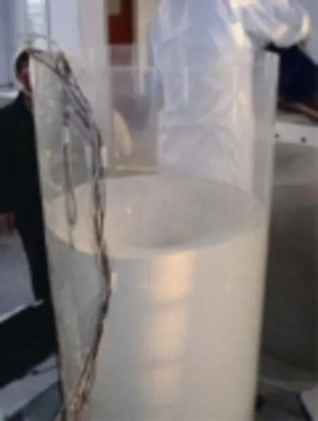
图2 筒仓卸料Fig.2 Discharging of sand

图3 测点C1~C15的动态侧压力变化曲线Fig.3 Dynamic wall pressure curves of C1-C15

表3 动态和静态压力试验值变化Table3 Experiment values change of dynamic and static pressures
由表3可以得知,除了仓壁与漏斗交接处的测点C1动态侧压力小于静态侧压力外,其余测点的动态侧压力均大于静态侧压力,而且最大超压系数出现在距仓壁底部高度为0.15 m的测点C4处,达到1.78,其次较大的超压系数为1.73,距仓壁底部高度为0.65 m的测点C11处。从侧压力增大幅度也可以看出,此超压系数较大两测点的压力增大超过了70%。由此说明此类筒仓的超压较大位置可能出现在邻近仓壁底部某一高度处及邻近仓壁的中部位置。
2 数值模拟
2.1 数值分析模型及材料参数
采用ABAQUS有限元软件进行筒仓卸料模拟。由于筒仓为中心对称结构,故取筒仓连同物料剖面的一半建立有限元模型,将仓内标准砂看作一平面对称单元,采用的单元名称为CAX4R。由于仓壁比标准砂的刚度大很多,故建模时将仓壁设置为刚性线。有限元模型及网格划分如图4所示。

图4 筒仓有限元模型及网格剖分Fig.4 Finite element model and mesh generation of silo
计算时有机玻璃筒仓的弹性模量取3 000 MPa,泊松比取0.3,重力密度取10 kN/m3。标准砂的弹性模量取为0.2 MPa,泊松比为0.4,并将标准砂考虑为塑性材料,选用子午线为线性的Druker-Prager模型模拟标准砂,标准砂的材料参数取值列于表4中。

表4 标准砂的材料参数取值Table4 Material parameters of standard sand
2.2 动态卸料模拟技术及数值结果
定义物料单元和仓壁之间的接触摩擦系数为0.43,选择有限滑动选项后进行网格剖分。计算分2个步骤:第一,通过模拟物料在自重作用下达到密实进行静态侧压力计算;第二,去掉静态侧压力模拟时卸料口处的约束进行筒仓卸料模拟,计算动态侧压力。模拟卸料过程中,线性施加物料重力,采用显式动态计算方法。在物料卸出过程中,网格会发生较大变形,因此利用ABAQUS软件中的自适应网格划分功能,可以减小网格畸形,有效延长卸料时间。在这一过程中,合理设置漏斗内物料单元的网格大小和计算频率是关键。
图5所示为卸料不同时间段漏斗口附近的网格变形及漏斗附近Mises应力分布图,可以看出物料卸出前,应力较大点发生在紧邻漏斗附近的仓壁处,卸料开始后,应力较大点即转向漏斗壁中部某范围,而且随着卸料时间的延长,此应力较大点的范围有所增大。

图5 简仓卸料不同时刻物料单元的网格变形及应力分布Fig.5 Mesh deformation and stress distribution during discharging of silo
3 静态和动态侧压力理论计算公式
根据目前成熟的Janssen理论,对立筒仓仓壁各测点的静态侧压力可以按如下公式计算:

对于贮料对仓壁的动态侧压力,根据中国《钢筋混凝土筒仓设计规范》(GB50077-2003)[30]4.2.2条进行计算:

公式(1)~(4)中各符号的含义如下:
Ch为深仓贮料水平压力修正系数,根据《钢筋混凝土筒仓设计规范》(GB50077-2003)表4.2.5计算,测点距仓壁底部的深度h为0~0.8 m时Ch=2,h=0.85时Ch=1.875,h=0.95时Ch=1.625,h=1.05时Ch=1.375;γ为贮料的重力密度,kN/m³;ρ为筒仓水平净截面的水力半径,m;μ为贮料与仓壁的摩擦系数;k为侧压力系数;s为贮料顶面或贮料锥体重心至所计算截面的距离,m;φ为贮料的内摩擦角,(°)。
4 结果分析
采用ABAQUS有限元软件对筒仓进行静态和动态侧压力模拟后,得到了仓壁不同深度测点的静态和动态侧压力值,将其描绘成曲线,如图6所示,并将按公式(1)~(4)计算的各测点侧压力值一同描绘于图6中以作比较。可以看出,静态侧压力计算值和模拟值比较吻合,相对误差绝对值在0.43%~9.92%之间,在0~0.2 m高度处,模拟值大于计算值,其他位置模拟值小于计算值;动态侧压力的模拟值与计算值吻合较好,相对误差绝对值在1.14%~9.65%之间,除测点C14和C15以外,模拟值均小于计算值。总的来说,各测点模拟曲线与计算曲线相对误差绝对值均小于10%,在合理范围,可以参见同领域相关文献[31-32]的误差范围,由此可见所选取的立筒仓有限元模型和动态卸料模拟技术是可行的。计算和模拟得到的仓壁各测点动态侧压力均明显大于静态侧压力,而且越接近仓壁下部,动态侧压力值比静态侧压力大的愈多,即超压系数愈大,当到邻近漏斗附近时超压系数达到某一较大值,随后超压减小,此侧压力变化趋势与实验测试结果是相同的。

图6 静态和动态侧压力模拟值和计算值曲线Fig.6 Static and dynamic wall pressure curve of numerical and calculated values
将仓壁不同深度处测点的静态和动态侧压力模拟值和试验值描绘成曲线,如图7所示。可以看出,静态侧压力模拟值和试验值曲线均较平滑,而且总体变化趋势均为仓壁下部大于上部;动态侧压力模拟值曲线较平滑,变化趋势与静态侧压力变化趋势相似,但是动态侧压力的试验值随仓壁高度的变化为不规则曲线,主要是由于动态卸料受随机干扰因素影响较大,故将动态侧压力试验值。拟合曲线一起绘于图7b中,发现拟合曲线与模拟曲线变化趋势相似,两者吻合较好。

图7 侧压力模拟值和试验值曲线Fig.7 Wall pressure curves of numerical and experimental values
为进一步比较侧压力模拟值和试验值的差异性,将静态侧压力模拟值和试验值及动态侧压力模拟值和试验拟合值的相对误差绝对值的最大值、最小值和平均值分别列于图7中,可以发现相对误差绝对值分别在1.83%~9.97%和0.28%~9.93%之间,各测点模拟与试验侧压力的相对误差绝对值均小于10%,是比较合理的计算结果,可以参见同领域相关文献[31-32]的误差范围,由此进一步验证了动态卸料模拟技术的可行性及相关参数选取的合理性。然而,无论是静态侧压力还是动态侧压力,相对误差绝对值都有个别测点达到9%左右,主要有以下原因:
1)材料属性问题,试验状态砂子为散体材料,模拟时虽然采用了Drucker-Prager准则,但还是近似地按连续介质考虑的;
2)流动状态问题,筒仓卸料时的流动状态一般分为整体流动和管状流动,整体流动时的动态侧压力要大于管状流动,试验时砂子为管状流动,模拟时无法精细地反映这一流动状态,所以模拟值多数大于试验值;
3)试验尤其是动态卸料试验,受随机干扰因素的影响较静态试验大,导致误差亦较大,因此,后续研究中,应加大试验次数,更为有效合理地进行试验设计和数据处理,减小误差,进一步提高试验数据精度和可靠度。
5 结 论
通过运用试验测试、数值模拟和计算公式3种方法对有机玻璃筒仓模型的静态和动态侧压力及卸料过程中的应力分布进行了分析研究,得到了一些有价值的结论:
1)筒仓动态侧压力大于静态侧压力,但是仓壁不同深度处测点的侧压力增大幅度不同,因此超压系数不同,在邻近漏斗附近某位置测点的侧压力增大幅度最大,超压系数达到1.78,在仓壁中部位置侧压力增大幅度较大,超压系数达到1.73和1.61,其他位置处侧压力增大幅度一般,超压系数在1.45以内。
2)静态侧压力和动态侧压力的模拟值与计算值、试验值或试验拟合值吻合度较好,说明了模拟方法的可行性和合理性;经过误差分析发现,个别测点的相对误差绝对值达到了9%左右,主要与模拟时的材料属性和流动状态问题及测试用压力传感器精度、标定试验和试验次数等随机因素有关,但大多数测点的误差都很小,而且各测点压力大小的分布规律比较合理。
3)数值模拟筒仓卸料时,漏斗口附近网格会发生较大变形,因此需要利用ABAQUS软件中的自适应网格划分功能,通过设置合理的网格以减小网格畸形导致计算中断,在此过程中,合理设置漏斗内物料单元的网格大小和计算频率是关键。
[1] 张少坤. 大直径钢筋砼筒仓温度荷载和贮料荷载作用有限元分析[D]. 武汉:武汉理工大学,2008.
Zhang Shaokun. Temperature Load and Storage Material Load Finite Element Analysis of Large-diameter Reinforced Concrete Silo[D]. Wuhan: Wuhan University of Technology, 2008. (in Chinese with English abstract )
[2] 马丽沙. 圆形筒仓在环境温度作用下的研究[D]. 西安:西安建筑科技大学,2015.
Ma Lisha. The Research of Temperature Effects on the Circular Silo[D]. Xiʼan: Xiʼan University of Architecture and Technology, 2015. (in Chinese with English abstract )
[3] 郭红伟. 大型落地式钢筒仓温度作用有限元分析[D]. 济南:山东大学,2013.
Guo Honwei. The Finite Element Analysis of Temperature Effects on Large Flat-bottom Squat Steel Silos[D]. Jinan: Shandong University, 2013. (in Chinese with English abstract )
[4] 宋靖. 大型高温贮料筒仓受力性能分析[D]. 杭州:浙江大学,2014.
Song Jing. Mechanical Behavior Analysis of Large Silos Storage for High Temperature Stored Materials[D]. Hangzhou: Zhejiang University, 2014. (in Chinese with English abstract )
[5] 尹君,吴子丹,张忠杰,等. 不同仓型的粮堆温度场重现及对比分析[J]. 农业工程学报,2015,31(1):281-287.
Yin Jun, Wu Zidan, Zhang Zhongjie, et al. Comparison and analysis of temperature field reappearance in stored grain ofdifferent warehouses[J]. Transactions of the Chinese Society of Agricultural Engineering (Transactions of the CSAE), 2015, 31(1): 281-287. (in Chinese with English abstract )
[6] 王学文,树学峰,杨兆建. 散料与锥仓接触模拟[J]. 农业机械学报,2010,41(10):86-90.
Wang Xuewen, Shu Xuefeng, Yang Zhaojian. Contact simulation on loose material and cone-shaped silo[J]. Transactions of the Chinese Society for Agricultural Machinery, 2010, 41(10): 86-90. (in Chinese with English abstract)
[7] Colonnello C, Reyes L I, Clémentb E, et al. Behavior of grains in contact with the wall of a silo during the initial instants of a discharge-driven collapse[J]. Physica A-Statistical Mechanics and Its Applications, 2014, 398: 35-42.
[8] Durmuş A, Livaoglu R. A simplified 3D.O.F.model of a FEM model for seismic analysis of a silo containing elastic material accounting for soil–structure interaction[J]. Soil Dynamic sand Earthquake Engineering, 2015, 77: 1-14.
[9] 刘立意,郝世杨,张萌,等. 基于CFD-DEM的稻谷通风阻力数值模拟与试验[J]. 农业机械学报,2015,46(8):27-32,158.
Liu Liyi, Hao Shiyang, Zhang Meng, et al. Numerical simulation and experiment on paddy ventilation resistance based on CFD-DEM[J]. Transactions of the Chinese Society for Agricultural Machinery, 2015, 46(8): 27-32, 158. (in Chinese with English abstract)
[10] 周长东,郭坤鹏,孟令凯,等. 钢筋混凝土筒仓散料的静力相互作用分析[J]. 同济大学学报:自然科学版,2015,,43(11):1656-1661,1669.
Zhou Changdong, Guo Kunpeng, Meng Lingkai, et al. Static interaction analysis of RC silo structure-granular material[J]. Journal of Tongji University: Natural Science, 2015, 43(11): 1656-1661, 1669. (in Chinese with English abstract)
[11] 杨鸿,杨代恒,赵阳. 钢筒仓散料静态压力的三维有限元模拟[J]. 浙江大学学报:工学版,2011,45(8):1423-1429. Yang Hong, Yang Daiheng, Zhao Yang. Three-dimensional finite element simulation of static granular material pressure for steel silos[J]. Journal of Zhejiang University: Engineering Science, 2011, 45(8): 1423-1429. (in Chinese with English abstract)
[12] 楼晓明,施广换,陈飞,等. 环锥型散体材料对筒仓侧壁的主动侧压力[J]. 岩土工程学报,2010,32(增刊2):25-28. Lou Xiaoming, Shi Guanghuan, Chen Fei, et al. Active lateral pressure of loop-cone shaped granular material against silo wall[J]. Chinese Journal of Geotechnical Engineering, 2010, (Supp.2): 25-28. (in Chinese with English abstract )
[13] 陈小辉,徐志杨,秦广乐. 筒仓卸料的离散单元法模拟[J].中国粉体技术,2011,17(5):61-64.
Chen Xiaohui, Xu Zhiyang, Qin Guangle. Distinct element method simulation of discharging in coal silos[J]. China Powder Science and Technology, 2011,17(5): 61-64. (in Chinese with English abstract)
[14] 刘震,王学文,杨兆建. 基于EDEM的筒仓静置与卸料侧压力模拟[J]. 中国农机化学报,2015,36(2):104-106,72.
Liu Zhen, Wang Xuewen, Yang Zhaojian. Simulation of lateral pressure during stewing and discharging in silos based on EDEM[J]. Journal of Chinese Agricultural Mechanization, 2015, 36(2): 104-106, 72. (in Chinese with English abstract)
[15] Uñac R O, Vidales A M, Benegas O A, et al. Experimental study of discharge rate fluctuations in a silo with different hopper geometries[J]. Powder Technology, 2012, 225: 214-220.
[16] Choi K, Mogami T, Suzuki T, et al. Experimental study on the relationship between the charge amount of polypropylene granules and the frequency of electrostatic discharges while silo loading[J]. Journal of Loss Prevention in the Process Industries, 2014, 32: 1-4.
[17] 林红,魏文晖,胡智斌,等. 钢筋混凝土筒仓库侧卸料静动态压力分布研究[J]. 土木工程与管理学报,2014,31(2):29-33.
Lin Hong, Wei Wenhui, Hu Zhibin, et al. Study on the static and dynamic lateral pressure of reinforced concrete silo under side discharge[J]. Journal of Civil Engineering and Management, 2014, 31(2): 29-33. (in Chinese with English abstract)
[18] Volpato S, Artoni R, Santomaso A C. Numerical study on the behavior of funnel flow silos with and without inserts through a continuum hydrodynamic approach[J]. Chemical Engineering Research and Design, 2014, 92: 256-263.
[19] Gallego E, Ruiz A, Aguado P J. Simulation of silo filling and discharge using ANSYS and comparison with experimental data[J]. Computers and Electronics in Agriculture, 2015, (118): 81-289.
[20] Wang Yin, Lu Yong, Jin Y O. Finite element modeling of wall pressures in a cylindrical silo with conical hopper using an Arbitrary Lagrangian-Eulerian formulation[J]. Powder Technology, 2014, 257(5): 181-190.
[21] Ding S, Li H, Ooi J Y, et al. Prediction of flow patterns during silo discharges using a finite element approach and its preliminary experimental verification[J]. Particuology, 2015, 18(2): 42-49.
[22] Volpato S, Artoni R, Santomaso A C. Numerical study on the behavior of funnel flow silos with and without inserts through a continuum hydrodynamic approach[J]. Chemical Engineering Research and Design, 2014, 92(2): 256-263.
[23] Mellmann J, Hoffmann T, Fürll C. Mass flow during unloading of agricultural bulk materials from silos depending on particle form, flow properties and geometry of the discharge opening[J]. Powder Technology, 2014, 253(2): 46-52.
[24] Ritwik M, Gargi D, Prasanta K D. Experiments on eccentric granular discharge from a quasi-two-dimensional silo[J]. Powder Technology, 2016, 31(11): 1054-1066.
[25] Ramírez A, Nielsen J, Ayuga F. Pressure measurements in steel silos with eccentric hoppers[J]. Powder Technology, 2010, 201(1): 7-20.
[26] 付建宝. 复杂条件下大型筒仓侧压力的极限分析与弹塑性有限元分析[D]. 大连:大连理工大学,2006.
Fu Jianbao. Limit Analysis and Elastio-plastic Finite Element Analysis of Lateral Pressure of Large Diameter Silo Under Complicated Conditions[D]. Dalian: Dalian University of Technology, 2006. (in Chinese with English abstract)
[27] 李胜利,王朝霞,王小慧. 不同方法分析大直径筒仓的侧压力比较[J]. 露天采矿技术,2010,(3):61-63.
Li Shengli, Wang Zhaoxia, Wang Xiaohui. Comparative analyses of large diameter silo lateral pressure with different methods [J]. Opencast Mining Technology, 2010, (3): 61-63. (in Chinese with English abstract)
[28] 孙巍巍,张园,孟少平,等. 基于三维离散单元法的大直径浅圆仓偏心卸料研究[J]. 南京理工大学学报,2014,38(3):414-418,423.
Sun Weiwei, Zhang Yuan, Meng Shaoping, et al. Eccentric discharge of large diameter squat silos based on threedimensional discrete element method[J]. Journal of Nanjing University of Science and Technology, 2014, 38(3): 414-418, 423. (in Chinese with English abstract)
[29] 尹冠生,黄义. 大型筒仓结构与地基的动力相互作用研究[J]. 空间结构,2002,8(3):41-50.
Yin Guansheng, Huang Yi. Analysis of dynamic interaction of large silo structure and ITS foundation[J]. Spatial Structures, 2002, 8(3): 41-50. (in Chinese with English abstract)
[30] GB50077-2003,钢筋混凝土筒仓设计规范[S].北京:中国计划出版社,2003.
[31] 刘定华,王建华,杨建斌. 钢筋混凝土筒仓侧压力的试验研究[J]. 西安建筑科技大学学报,1995,27(1):8-12.
Liu Dinghua, Wang Jianhua, Yang Jianbin. An experimental study of the lateral pressure on the wall of reinforced concrete silo[J]. Journal of Xi'an University of Architecture & Technology, 1995, 27(1):8-12. (in Chinese with English abstract)
[32] 刘定华,魏宜华. 钢筋混凝土筒仓侧压力的计算与测试[J].建筑科学,1998,14(4):14-18.
Liu Dinghua, Wei Yihua. Calculation and testing of lateral pressure in a reinforced concrete silo[J]. Building Science, 1998, 14(4): 14-18. (in Chinese with English abstract)
Simulation and experimental validation of silo wall pressure during discharging
Zhang Daying1, Xu Qikeng2, Wang Shuming3, Liang Xingpei2
(1. School of Civil Engineering, Zhengzhou University of Aeronautics, Zhengzhou 450015, China; 2. School of Civil Engineering and Architecture, Henan University of Technology, Zhengzhou 450001, China; 3. Zhengzhou University Multi-functional Design and Research Academy Co.. Ltd., Zhengzhou 450002, China)
Wall pressure especially dynamic wall pressure of the single silo is crucial for the silo design. Therefore, it’s necessary to obtain static and dynamic wall pressures, as well as their change regularity along the silo wall. In view of this, 2 techniques were mainly used in this study containing experimental method and simulation technique in order to solve the aforementioned problem. Apparently, it is difficult and intractable to study and discuss wall pressures of the silo during discharging. Nevertheless, it is direct and efficient to carry out experiment on this issue, so we carried out this test in Structure Laboratory of Henan University of Technology. In this experiment, the test object was a miniature silo model of organic glass due to its transparency to materials. We could clearly observe flow patterns of materials inside the silo. The silo model was full of standard sand, and sensors were pasted on the internal surface of the silo wall to record test data. The static wall pressure was tested after the silo model was filled up, and the dynamic wall pressure was tested during discharging. In order to obtain accurate experimental results, tests with many times had been done. On the other hand, for mutual authentication, ABAQUS software was employed to simulate the flow of material during discharging. The finite element model (FEM) was two-dimensional (2D) model with a rigid line representing the silo wall and a plane representing the material. In this process, surface-to-surface contact was used, and the silo wall and the material boundary were set to the target and contact element respectively. What was more, adaptive mesh subdivision technology was very important, for time duration of material discharging was directly affected, and it lasted 0.25 s in the process. In addition, some phenomena appeared in Mises stress cloud charts. The larger the Mises stress changed from the silo wall to the hopper wall, the larger the stress area on the hopper wall increased over time. Moreover, in order to verify the experimental and numerical results, theoretical formulae in Chinese code were used to calculate static and dynamic wall pressures, and it was verified that the calculated values were large influenced by the wall pressure coefficient. After that, experimental results, simulation results and theoretical values were also obtained and compared with each other. It was shown that dynamic pressures were bigger than the static ones; the maximum overpressure coefficient reached 1.78 at 0.15 m, the second larger overpressure coefficient reached 1.73 at 0.65 m, and thus the dynamic pressures increased by over 70% compared with the static pressures for the 2 measure points. About the other measure points, the overpressure coefficient was less than 1.45, and the minimum was 0.99. The other comparative results showed that the difference between simulated values and theoretical values of the silo wall pressure was small. To some extent, it was more or less different between experimental values and simulated values due to sensor accuracy and calibration test errors, but the variation tendency of static wall pressure was almost the same; in addition the dynamic pressure was affected larger than the static pressure by the above factors, and therefore the experimental curve was a little irregular, while the simulated curve of it was more smooth. And then, some helpful phenomena appeared through data analysis of measure points, for example, dynamic wall pressure amplitude of each measure point was different, and the maximum was next to the hopper; the higher value was nearly in the middle of the silo wall. Through the above analysis, the proposed simulated and experimental method are also feasible to obtain static and dynamic wall pressures of the silo, and the obtained change regularity of pressures along the silo wall is useful for the silo design and further research.
silo; models; finite element method; experimental study on wall pressure; simulation technique during discharging
10.11975/j.issn.1002-6819.2017.05.039
TU317+.1
A
1002-6819(2017)-05-0272-07
张大英,许启铿,王树明,梁醒培. 筒仓动态卸料过程侧压力模拟与验证[J]. 农业工程学报,2017,33(5):272-278.
10.11975/j.issn.1002-6819.2017.05.039 http://www.tcsae.org
Zhang Daying, Xu Qikeng, Wang Shuming, Liang Xingpei. Simulation and experimental validation of silo wall pressure during discharging[J]. Transactions of the Chinese Society of Agricultural Engineering (Transactions of the CSAE), 2017, 33(5): 272-278. (in Chinese with English abstract) doi:10.11975/j.issn.1002-6819.2017.05.039 http://www.tcsae.org
2015-11-30
2016-12-30
国家自然科学基金资助项目“基于环境激励的钢筋混凝土立筒群仓动力相互作用机理研究”(51178164);郑州市科技计划项目“立筒仓的动力测试优化与动力特性研究”(20140586)
张大英,女(汉族),山东淄博人,讲师,博士,主要从事粮仓结构动力问题计算、测试与分析。郑州 郑州航空工业管理学院土木建筑工程学院, 450015。Email:daying803@126.com
