Numerical investigation of penetration in Ceramic/Aluminum targets using Smoothed particle hydrodynamics method and presenting a modified analytical model
2017-03-19EhsanHedayatiandMohammadVahedi
Ehsan Hedayati and Mohammad Vahedi
1 Introduction
Resistance against impacts, whether at high velocity or low velocity, is among the important parameters considered in the design of shields. According to available literature on shield design, a shield can provide high efficiency when it is of such characteristics as low density,high resistance against failure by tensile stresses, and large volumetric and shear module, i.e.high stiffness. Single-layer metallic shields cannot satisfy all of the mentioned features because of high density of metallic materials. Materials such as ceramic, however, can provide all of the features except for high resistance against failure by tensile stresses. As such, researchers have attempted to design composite shields with a ceramic layer in front and a metallic/composite layer behind that (serving as a support layer), so as to optimally provide all characteristics of an efficient shield. In different applications, ceramic shields are usually reinforced using some support. The support layer absorbs residual kinetic energy of the intender once the ceramic layer is failed, enhancing ceramic stability in the course of absorption process. The thicker the support layer, the lower will be the likelihood of ceramic failure due to deformation of the support sheet [Tate (1967); Chocron Benloulo et al. (1998); Taylor (1948); liaghat et al. (2013)].Support composite absorbs kinetic energy of crushed fragments, stopping them from further movement. Given these factors, the design of these shields was an extremely complicated task which required modern pieces of equipment for conducting the required tests [Taylor (1948); liaghat et al. (2013)].
This is while, multi component shields, particularly those with a hard ceramic upper layer together with a deformable support sheet, can address the mentioned problems. Accordingly,once a projectile collide a ceramic target supported with a metallic sheet, conical failure happens due to the reflection of tensile waves, so that this ceramic cone transfers the load resulted from the projectile collision to the support layer across an area of larger extension at cone base [Tate (1967); Chocron Benloulo et al. (1998); Taylor, 1948; liaghat et al. (2013)].Development and evolution of light-weight shields for such applications as vehicles, aircrafts,and security equipment, where the weight is a key design factor, has been very remarkable. As the shield weight increases, vehicles and aircrafts end up with higher fuel costs. As such,ceramic/metal shields are among composite shields which can provide required characteristics for better efficiency of a shield. Optimally designing ceramic/metal shields for minimizing areal density of the shield, it is found that, bran carbide and silicon carbide ceramics are preferred for such a purpose, because of their low density and high strength. As such, when applied together with metallic materials (as support), ceramic targets (shields) have gained larger deals of attention during recent years because of their high efficiency against small to medium projectiles [Chocron Benloulo et al. (1998); Taylor (1948); liaghat et al. (2013)].
Numerous works have been performed to investigate the phenomenon of penetration into ceramics analytically, among which one can refer to the models presented by Tate,Fellows, Florence, Liaghat, Chocron Benloulo, etc. [liaghat et al. (2013)].
The first significant numerical analysis of ceramic targets was performed by Florence. He presented an analytical model for a two-layer composite shield (composed of a hard ceramic layer and a formable support material) against a rigid cylindrical projectile. This model predicts ballistic limit velocity which indicates resistance of the shield against penetration. Florence’s model exhibited satisfactory agreement with experimental results.Therefore, in the Florence’s model, the kinetic energy of the projectile colliding the target was balanced against the absorbed energy by the support sheet to obtain ballistic limit velocity. Because of its simplicity, this model gained a large deal of attention from many researchers [Florence (1969)].
On this basis, Hetringtone [Hetherington (1992)] proposed an optimal design method for calculating the thickness ratio and thicknesses of ceramic and composite which give the best protection for a given areal density.
Of analytical models presented for penetration into ceramic targets, one may refer to the analytic model presented by Wilkins et al. This numerical analysis was performed to simulate collision in vertical impacts using a finite difference code called HEMP. The studies performed by Wilkins et al. showed that, for optimal design of a two-component ceramic system, projectile-system interactions shall be considered appropriately [Wilkins(1978)].
Later on, Woodward presented a one-dimensional analytic model for complete penetration into a ceramic shield using so-called constitutive equations. Taking into account ceramic and projectile erosion and using thick and thin support sheets, Woodward obtained ballistic limit velocity and penetration depth [Woodward (1990)]. Cortes et al. presented a numerical model which two-dimensionally analyzed the collision of a cylindrical projectile with a ceramicmetal shield. In this numerical model, macroscopic material behavior within the region where the ceramic was being eroded was presented using a compositional model wherein internal friction and volumetric expansion were taken into account [Cortes R et al. (1992)]. Lee et al.used numerical methods to consider the impact of a steel projectile onto a light-weight ceramic shield while studying such phenomena as projectile erosion, crack propagation,conical structure of ceramic, and support sheet failure [Lee et al. (2001)]. Also, Simha et al.used a computational model and finite element model to consider the response of semiinfinite ceramics of high purity (e.g. 99.5% alumina) in collision with a long rod projectile and obtained good results with reference to experimental data [Simha et al. (2002)].
In the analytic model proposed by Den Reijer, projectile eroding and mushrooming phases were investigated, with a discussion given on different models describing the deformation of support sheet. Furthermore, equations were presented for the behavior of crushed ceramic [Reijer (1991)]. Zaera presented a one-dimensional model for simulating ballistic collision with constrained ceramic/metal targets. In this model, the projectile penetration into ceramic is based in Tate and Alekseevskii’s equations while the support sheet response is based on Woodward’s and Den Reijer’s models [Zaera et al. (1998)]. In the model proposed by Fellows et al., considering the three phases of projectile eroding,mushrooming, and rigidity, constitutional equation was applied to the projectile, ceramic,and support sheet to predict penetration depth into ceramic shields supported by semiinfinite sheets [Fellows et al. (1999)].
Wang [Wang et al. (1996)] proposed a design criterion to calculate optimal thickness ratio at which optimal efficiency of a two-component composite shield was produced for a given total thickness. Ben-Dor [Ben-Dor et al. (2000)] presented an optimal design for two-component shields for dimensionless case, wherein all properties of the projectile and shield were described as functions of independent parameters. Shi and Grow [Shi et al. (2007)] investigated two-component shield optimization problems considering two constraints at the same time, namely total thickness and areal density.
In empirical models, experimental data are used to derive algebraic equations governing the data and then employ the equations to predict parameters of interest. As of current,numerous empirical models have been proposed on the subject matter of penetration into ceramic targets, among which one can refer to the experiments presented by Bless et al.[Bless et al. (1987)] and Myseless et al. [Myseless et al. (1987)].
Considering the above-mentioned references along with numerous other research works,it seems that, the understanding of the behavior exhibited by ceramic/metal composites under ballistic impact demands for more precise and in-depth studies, so that all of the three approaches (i.e. experimental, analytical, and numerical) shall be followed when investigating and analyzing the phenomenon of penetration into a ceramic/metal target.Because of their high reliability, experimental methods are the most appropriate ones for such a purpose; however, these methods give no information about loading history and the changes occurred during the course of penetration process, while being well expensive. The second approach where the penetration phenomenon is theoretically and analytically considered represents a simple and fast method for achieving the desired results.
Numerical methods, such as smoother-particle hydrodynamics (SPH), are among the most suitable methods for analyzing penetration problems, particularly those into ceramic targets, as those solve all of the equations governing continuous media, lower the required time and cost of undertaking such analyses, and can be used in a wide spectrum of applications [Tate (1967)].
Intending to characterize behavior of ceramic/aluminum composites, the present research goes for investigating the deterioration of ceramic supported with aluminum sheet both numerically and analytically. Further, in order to study impact strength of and penetration depth into ceramic/aluminum composites, a modified analytic model is presented, with its results compared to the results of Florence’s analytic model and impact modeling using SPH method.
2 Smoothed particle hydrodynamics method
Smoothed particle hydrodynamics method is one of the numerical methods classified as meshless analysis methods. In meshless analysis methods, unlike finite elements methods,the need to define a standard element for interpreting physical behavior is obviated, and instead in these methods the cluster of nodes is substituted for grid elements [Bonet et al.(1999)].
These methods are basically appreciated by virtue of reducing a lot of time which would be spent on mesh generation, especially in adaptive dynamic analyses, if finite element method was applied. One of the reasons attracting attention to this method is the fact that equations are written in a fixed coordinate and free moving of nodes with intense localized materials can be handled. The importance of this ability of SPH is obvious especially in problems involving extra-large deformations [Bonet et al. (1999)].
SPH method is based on expressing the numerical value of nodes as weighted average over the numerical values of the neighbor nodes. The advantage of this method over the finite element method is its ability to simulate mediums with complex geometries and inhomogeneous nodes distribution [Bonet et al. (1999)].
SPH method in the realm of stress analysis problems or so on includes spreading finite nodes over the considered problem environment and converting continuous problem to a discretized one into the mentioned nodes. These nodes are accelerating and moving due to their applied hydrostatic pressure or effective stress. By means of a special function,known as smoothing function, which is required to have the following properties, effect of each node on its neighbor nodes is revealed. The previously mentioned properties of smoothing function include [Liu & Liu (2003)]:
1) Weight function is always positive in the smoothing domain W^(x,h) > 0 > 0.
2) Weight function is always zero outside the smoothing domain W^(x,h)>0 = 0.
3) Weight function is one-to-one
4) Wight function is bell-shaped.
5) As smoothing domain (h) approaches zero, weight function approximates to Dirac delta function W^(x,ℎ)> 0
In above equations, W^ is smoothing function or weight function, h is a parameter determining the effective (or smoothing) domain of function andis problem domain.All properties of interest in the problem, including stress, pressure, density, etc. are linked to each other by this function [Liu & Liu, 2003]. SPH method takes advantage of the integral representation of functions. To describe this approach, function u(x) is defined for each point X =. Integral representation of this function is as shown in Equation (1) [Liu & Liu & Lam, 2003]:


In this equation, 〈u(x)〉 is approximate function, W(x − xi,h) is smoothing function, and h is smoothing length in SPH method. It can be proved that the adopted approximation in SPH method is of second order accuracy. Because problem analysis in SPH method, as it is seen in Figure 1, is associated with distributing finite nodes in the domain of interest and calculating based on them.

Figure 1: Distribution form of nodes and determination of neighbors in SPH method [Liu& Liu & Lam (2003)]:
3 Modified analytic model for ceramic/metal target
Radius of ceramic cone plays an important role in predicting ballistic limit velocity.Therefore, radius of ceramic cone can impose large contributions into final solution of the analytical models used for penetration into ceramic/metal targets. The relationships and equations proposed by Florence for the radius of ceramic cone are based only on ceramic thickness. However, given that the support (metal) layer plays a significant role in the final strength (both during penetration and at failure) of a ceramic/metal composite,radius of ceramic cone may not be dependent on the ceramic thickness only, but rather further dependent on the support layer thickness. This suggests a revision and modification to the Florence’s equations for the radius of ceramic cone.
3.1 Modification of the equations for radius of ceramic cone in florence’s model
As demonstrated in Figure 2, the modified equations presented in this analytic model are considered in two phases. In a first phase, the equations are considered for the case when only ceramic layer is penetrated. The second phase, however, considers and suggests modifications for the case when a projectile penetrates into both the ceramic layer and the support layer completely.
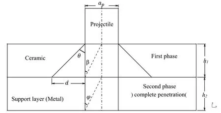
Figure 2: A schematic of the collision between projectile and target and formation of ceramic cone.
Considering Figure 2, the equation of radius of ceramic cone in Florence’s model is expressed as Equation (3) [Florence (1969)]:

Where a is the radius of ceramic cone, apis the projectile radius, and h1is ceramic thickness.
Expressing Equation (3) as a function of angle of ceramic cone while considering Figure 3 in the first phase, one can end up establishing Equation (4) [Florence, 1969]:

Where θ is half-angle of the ceramic cone. Equation (4) describes the effect of half-angle of the cone on the relationships describing radius of the ceramic cone.
The half-angle of a cone can be determined using Equation (5), which is derived from Fellows’ analytic model [Fellows et al. (1999)]:

Where VPis initial projectile velocity and π is in degrees with its value been equal to 180.In Figure 2, formation of ceramic cone in the first phase and complete penetration in the second phase can be observed. Accordingly, one can modify Equation (7) for the effect of support layer thickness (h2) to come with Equation (7):

Figure 3 indicates the formation of cone angle in the first phase. Therefore, one can present Equations (8) and (9) as follows:


Figure 3: Schematic of the formation of ceramic cone in the first phase.
Being independent of the ceramic thickness, Equation (10) can be obtained by dividing Equation (8) by Equation (9):

In order to obtain the angle β, one can rewrite Equation (10) as Equation (11).Accordingly, the value of angle β is obtained as follows:

According to Equations (7), (12) and (13) and considering Figure 4, provided h1<h2,angle φ (which is formed in the second phase, i.e. complete penetration) can be obtained using Equation (14):

According to the law of cosines [Gentile, 2015], the value of angle γ is expressed as in Equation (15):


Figure 4: Schematic of the composition of the cone radius of the first phase in the second phase assuming h1<h2.
According to Equations (7), (16) and (17) and considering Figure 5, provided h1>h2,angle φ (which is formed in the second phase, i.e. complete penetration) can be obtained using Equation (18):


Figure 5: Schematic of the composition of the cone radius of the first phase in the second phase assuming h1>h2.
Equation (7) will largely affect Equation (19), i.e. the mass function developed for the projectile and target. Moreover, Equation (19) [Florence (1969)] is of paramount importance in predicting ballistic limit velocity using Equation (20) [Florence (1969)],indicating the effect of radius of ceramic cone on ballistic limit prediction.

Where f(a) is the mass function developed for projectile and target, Vblis ballistic limit velocity, ε2is the strain at failure of support layer, σ2is ultimate tensile strength (UTS)of the support layer, ρ2is the density of the support layer, h2is the support layer thickness, ρ1is ceramic density, h1is ceramic thickness, and Mpis projectile mass., etc.
4 Problem modeling on ceramic/aluminum target using smoothed particle hydrodynamics (SPH)
Projectile was selected from steel 4340 type and the targets were two square-shape planes of aluminum 6060-T651 and ceramics of SiC with dimensions of 100×100×t mm .Only the thickness of ceramic and aluminum planes are varying but the final total thickness of the target remained constant (10 mm). The supports of the planes in four directions are completely rigid (all degrees of freedom are zero). Figure 6 and 7 show the boundary condition and Projectile, respectively. Mechanical properties and the state equations of the ceramic target are listed in table 1 [Johnson et al. (1997); Johnson et al.,1994; Abaqus (2014)]; mechanical properties and state equation of Projectile plane and aluminum target are shown in table 2 [Ulven et al. (2003); Piekutowski et al. (1996);Steinberg (1996); Corbett (2006); Johnson & Cook (1985); Schwer (2009)]. The Projectile is thrown in vertical direction (respective to the target plane) with initial velocity of 8. As such, this problem is modeled in 8 different cases, and the results obtained by varying the velocity parameter are investigated by comparing the smoothed particle hydrodynamics (SPH) method to analytical models.

Figure 6: boundary condition of the numerical model and 3D solid element meshes used in the numerical simulations.
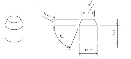
Figure 7: discretization of projectile in 2 and 3 dimensions [Ulven et al., 2003]
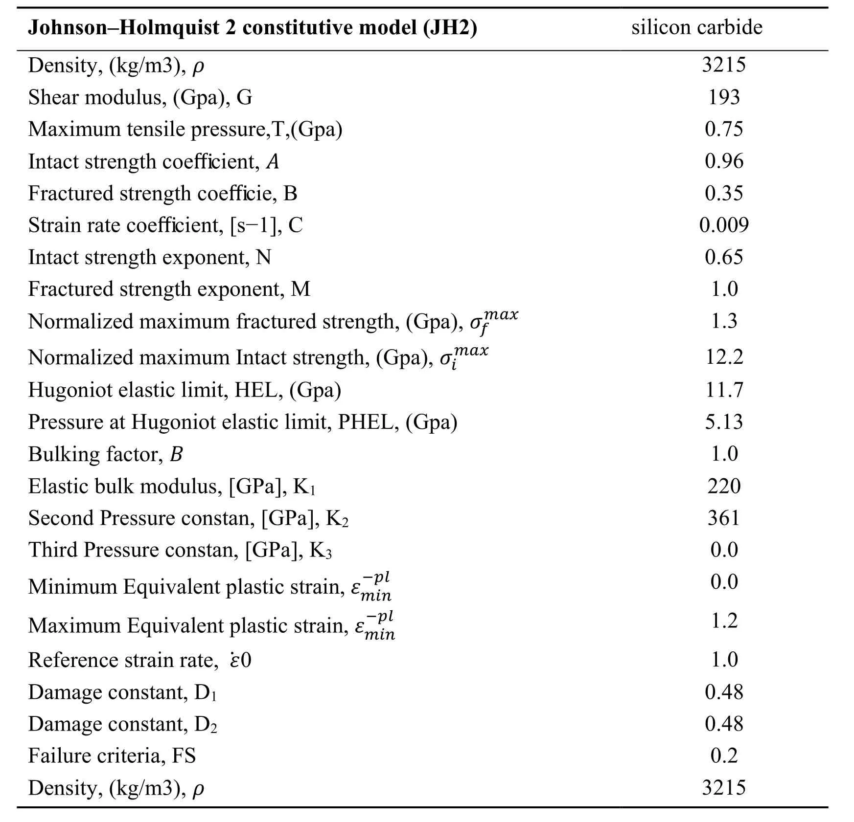
Table 1: coefficients and properties of SiC in Holmquist model

Table2: Mechanical properties and Johnson-Cook model parameters for the Materials

Ultimate Stress, (MPa),σuts Specific heat, (J/Kg/° C)Elongation at Break,%,εf Reference strain rate, ε˙0 A [MPa]B [MPa]n c m Tm (°C)T0 (°C)Initial failure strain, D1 Exponential factor, D2 Triaxiality factor, D3 Strain rate factor, D4 Temperature factor, D5 310 885 17 0 262 161.2 0.2783 0 1.34 925 293.2-0.77 1.45 0.47 0 1.6 1110 477 13.2 0.15 1430 2545 0.7 0.014 1.03 1793 293.2 0.05 3.44 2.12 0.002 0.61
Plasticity structural model and Johnson-Cook (J-C) failure model were used for modeling and simulating the projectile and the aluminum plate. J-C model expresses yield stress as in Equation (21) [Johnson et al., 1997]:

Where ε is equivalent plastic strain;ε˙∗= ε˙/ε˙0is dimensionless strain rate; ε˙0=1s−1; T*is homologous temperature and can be calculated as T∗=T−Tr/Tm−Tr; Tmis the melting temperature and Trshows the room temperature; P is hydrostatic pressure; 0≤T∗≤ 1; A and B are dynamic yield stress and stiffness constant, respectively; and N, M,and C are material constants. Even though this model is an empirical one, it is well flexible and powerful and accounts for the effects of important parameters. As the temperature approaches toward melting point (T* = 1), strength tends to zero. J-C model is based on damage accumulation, i.e., as the element fails as the damage reaches D = 1.Following the failure, the material behaves as a liquid as it has no strength (no shear and deviatory stress) and is unable to generate any hydrostatic tensile stress, being only capable of bearing hydrostatic pressure. Moreover, an increase in damage may end up with a gradual decrease in strength, making the material so-called “soft”. Damage to an element can be written as Equation (22):

Where the nominator represents equivalent plastic strain rate and denominator is equivalent strain-to-failure.
The general expression for strain-to-failure is given by Equations (23) and (24) [Johnson et al., 1997]:

where σ∗= σm/σ is the dimensionless stress-pressure ratio, σmis the average of the three principal normal stresses, σis von Mises equivalent stress, ε˙∗is dimensionless strain rate, and T* is homologous temperature.
For modeling and simulation of ceramic plane, plasticity structural model and Johnson -Holmquist model were used.
Johnson-Holmquist plastic failure model is suitable for ceramics, glass and other brittle materials. Normalized equivalent stress based on D failure parameter is in the form of equation (25) [Johnson et al. (1994)]:


σ is the real equivalent stress and σHELshows the stress at Hugoniot Elastic Limit (HEL).Initial resistance and normalized fracture are as equations (27) and (28) [Johnson et al.,1994]:

It must be noted that, the normalized fracture resistance can be limited asN ,M ,C ,B and A are material constants.The normalized pressure is the result of dividing real pressure to HEL pressure.Normalized Maximum Tensile Hydrostatic Pressure can be obtained by a fraction whose numerator is the Maximum Tensile Hydrostatic Pressure. The dimensionless strain rate can be also obtained by dividing the real strain rate to the reference one (equation 29-30):

Where T* is the normalized maximum tensile fracture: ε˙0=1.0s−1and the failure accumulation is in form of equation (31).


Hydrostatic pressure before the fracture (D=0) is in form of equation 33.
(μ = ρ/ρ0− 1) Converts to equation (34) for tensile pressures which neglects the energy effects. Bulking occurs after failure accumulation (D>0) and the pressure intervals which can be determined by energy considerations will be added in the form of equation 35 [Johnson et al., 1994]:

Abrasive models are also include in these data/ the task of this model elements’ abrasion at the time of strain or other cases are defined relative to definite strain and so on. This model has wide application in impact and penetration fields. The element abrasion is the base of failure and fracture in penetration model and on the other hand, in such problems,elements may have too much distortion and result in “bad-structured elements” and the Gaussian points may be negative. This makes the simulation instable and causes error[Johnson et al. (1994)]. This model is necessary to avoid too much distortion of the elements.
5 Numerical model verification
In the course of the process through which the projectile penetrates into the target,considering the target material and geometrical parameters of the projectile, part of initial kinetic energy of the projectile is absorbed by the target. As such, a structure can serve as an energy absorber when it is capable of tolerating maximum stress at which it can exhibit maximum strain or deformation. So, calculation of residual velocity of a projectile is of paramount importance when it comes to impact modeling. In order to calculate post-damage residual velocity of rigid projectiles in any plate (i.e. metallic,composite-made, ceramic, etc.), one can use Recht and Ipson model; this analytical model is expressed as Equation (36):

Where Mpis the projectile mass, V0and Vrare impact velocity and residual velocity of the projectile, respectively, and W denotes the work performed at target (at full penetration).
This performed work is, indeed, equal to the absorbed energy. Therefore, ballistic limit velocity of the projectile,Vbk, in the Recht and Ipson analytical model is expressed by Equation (37) [Rosenberg et al. (2016)]:

5.1 Trend of solution convergence of numerical model based on mesh size
Considering Figure 2, critical and non-critical zones of the target body and projectile were meshed used the 3-dimensional elements of PC3D, C3D8, and C3D8, respectively.The elements should be considered not only in terms of shape, but also in terms of size.For this purpose, one should investigate convergence of solutions, which is an essential issue that ensures accuracy of the results. When investigating convergence of solutions,which contributes to higher accuracy as the elements become finer, it should be noted that only elements within critical zones of the model should become finer. Therefore, in the aforementioned model, only critical zone of the target is subjected to element size change, with the size of elements within non-critical zones of the target and projectile been assumed to be fixed and unchangeable.
In order to observe the trend of solution convergence of the model, element size across the critical zone was varied according to Table 3, while size of the elements across noncritical zone and projectile were assumed to be 3 and 1.5 mm, respectively. According to Table 4, it is seen that, for element sizes of 0.6, 0.55, 0.5, and 0.45 mm, the solutions converged. As such, the 0.60 mm was selected as the optimum element size across the critical zone of the model as the time to solve the problem would be shorter than that with an element size of 0.45 mm while the resulting difference in the solutions was negligible.
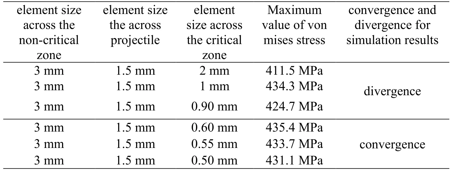
Table 3: Trend of solution convergence of numerical model based on mesh size
5.2 Impact trend and target destruction
To observe the trend of structural destruction under impact, figures 8-14 show the structure destruction trend for projectile velocity of V0= 675 m/s for different time intervals by the help of Smoothed particle hydrodynamics (SPH) method. As it can be seen, by decrease of aluminum thickness and increase of ceramic thickness, the residual velocity of the projectile will be decreased.

Figure 8: target and projectile position at the initial time(ceramic and aluminum thicknesses are 3 and 7 mm, respectively)

Figure 9: target and projectile position after 0.010013(ceramic and aluminum thicknesses are 3 and 7 mm, respectively)

Figure 10: target and projectile position after 0.050012(ceramic and aluminum thicknesses are 3 and 7 mm, respectively)

Figure 11: target and projectile position after 0.030009(ceramic and aluminum thicknesses are 4 and 6 mm, respectively)

Figure 12: target and projectile position after 0.050025(ceramic and aluminum thicknesses are 4 and 6 mm, respectively)

Figure 13: target and projectile position after 0.020015(ceramic and aluminum thicknesses are 6 and 4 mm, respectively)

Figure 14: target and projectile position after 0.060002(ceramic and aluminum thicknesses are 6 and 4 mm, respectively)
5.3 Validation and investigation of the variations of ceramic cone radius, projectile velocity and penetration time
The variation of ceramic cone radius, projectile velocity and penetration time will be investigated in this section. As in this project impacts occur at high velocities, the projectile will leave the structure with a non-zero residual velocity.
In this modeling, the ceramic cone radius, projectile initial velocity, boundary conditions and the support states are among the effective factors on the penetration time and the projectile output velocity.
Initial velocity: as expected, by increase of initial velocity of the projectile. The time needed for its penetration into the target and reaching to a residual stable velocity will decrease and the energy would decrease as well.Boundary condition: in low initial velocities, type and boundary conditions are more important, but by increase of projectile initial velocity, the effect of supports will be reduced. So, as in this research, the collisions are in high velocities, the effect of support type on the projectile passing velocity is negligible.
For detailed analysis of impact resistance in ceramic/aluminum target and fracture mechanism, investigation of formation of ceramic cone radius is necessary. To completely presents the ceramic conic radius for analytical Florence model and the modified analytical model, the initial velocity-ceramic cone radius is presented for ceramic/aluminum 6061-T651 target with different thicknesses in figure 15. According to figure 15, the maximum error in the modified model is negligible in comparison with Florence analytical model. According to figure 15, there is no need to detailed adaption of the obtained data; the main goal is to adapt the presented method with the Florence analytical method. Therefore, the data of the modified model exactly confirm the Florence analytical model. Also, the mentioned plot showed that by increase of initial velocity and ceramic thickness and decrease of supporting layer thickness, the ceramic cone radius increased which could result in projectile residual velocity decrease and increase of penetration time and pressure distribution level regarding the cone depth.
Hence, the ceramic cone radius is an effective factor in increasing the conic fracture efficiency. To present Recht-Ipson model for the modified analytical model and also Florence model and Smoothed particle hydrodynamics method, according to figures 16 to 19, the initial velocity- residual velocity-ceramic cone radius is presented for ceramic/aluminum target in different thicknesses.To present Recht-Ipson model for the modified analytical model and also Florence model and Smoothed particle hydrodynamics method, according to figures 16 to 18, the initial velocity- residual velocity-ceramic cone radius is presented for ceramic/aluminum target in different thicknesses.

Figure 15: comparison of conic radius in terms of initial velocity for Florence and modified models.

Figure 16: comparison of initial velocity-residual velocity-ceramic cone radius for Florence, modified and SPH methods.

Figure 17: comparison of initial velocity-residual velocity-ceramic cone radius for Florence, modified and SPH methods.

Figure 18: comparison of initial velocity-residual velocity-ceramic cone radius for Florence, modified and SPH methods.According to figures 16-18, there is no need to detailed adaption of the obtained data; the main goal is to adapt the Smoothed particle hydrodynamics method with the Florence analytical model and the presented analytical model. Therefore, only the data extracted from curves 16-18 and the simulation results of tables 4-5 will be presented.According to figures 16-18, there is no need to detailed adaption of the obtained data; the main goal is to adapt the Smoothed particle hydrodynamics method with the Florence analytical model and the presented analytical model. Therefore, only the data extracted from curves 16-18 and the simulation results of tables 4-5 will be presented.
According to table 4, it can be seen that when the ceramic and aluminum thicknesses are 3 and 7 mm, respectively, the error percentage of residual velocity in Smoothed particle hydrodynamics relative to the modified and Florence models is 2.114 and 2.070%,respectively. Also, according to table 5, it can be seen that when the ceramic and aluminum thicknesses are 6 and 4 mm, respectively, the maximum residual velocity error of Smoothed particle hydrodynamics method relative to the modified model and Florence model is 1.710 and 1.761%, respectively. The acceptable error is 6-12% and is suitable for concluding on the impact behavior of the target. Hence, the data of Smoothed particle hydrodynamics method highly confirm the residual velocity in the modified analytical model and also Florence model.
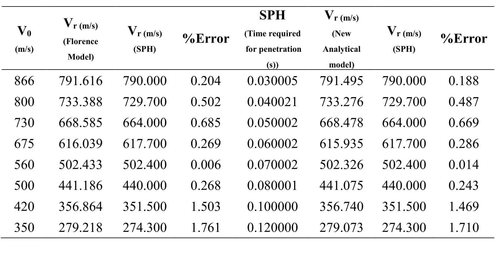
Table 5: the output velocity of the projectile in terms of initial velocity for Florence,modified and SPH methods (ceramic and aluminum thicknesses are 6 and 4 mm,respectively).
5.4 Impact resistance efficiency in ceramic/aluminum target
For further investigation of the effect of ceramic cone radius, ceramic and support layer on residual velocity and target’s absorption, figures 19-21 are presented.
According to figures 19-21, there is no need to detailed adaption of the obtained data; the main goal is to adapt the Smoothed particle hydrodynamics method with the Florence analytical model and the presented analytical method. Therefore, only the data extracted from curves 19 and 21 and the simulation results of tables 6-7 will be presented. Based on table 6, when ceramic and aluminum thicknesses are 3 and 7 mm, respectively, the maximum absorbed energy error in Smoothed particle hydrodynamics method relative to the modified and Florence models is 6.712 and 6.829%, respectively.
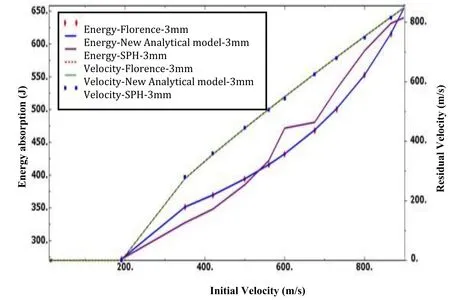
Figure 19: comparison of initial velocity-residual velocity-absorbed energy for Florence,modified and SPH methods.

Figure 20: comparison of initial velocity-residual velocity-absorbed energy for Florence,modified and SPH methods.

Figure 21: comparison of initial velocity-residual velocity-absorbed energy for Florence,modified and SPH methods.

Table 6: absorbed energy versus the initial velocity for modified and SPH method.(Ceramic and aluminum thicknesses are 3 and 7 mm, respectively)
Also, according to table 7, it can be seen that when the ceramic and aluminum thicknesses are 6 and 4 mm, respectively, the maximum absorbed energy error of Smoothed particle hydrodynamics method relative to the modified model and Florence model is 5.470 and 5.602%, respectively. Hence, the data of Smoothed particle hydrodynamics method confirm the absorbed energy results of the modified analytical model and also Florence model with high accuracy.

Table 7: absorbed energy versus the initial velocity for modified and SPH method.(Ceramic and aluminum thicknesses are 6 and 4 mm, respectively)
Therefore, by increase of ceramic thickness, the data of SPH method confirm the modified analytical model with higher accuracy; but SPH method confirms both modified and Florence models with high accuracy.
The obtained tables also suggest that by increase of ceramic thickness and decrease of the supporting layer (aluminum), the residual velocity of the projectile will decrease and the energy absorption of the target will be enhanced which could be due to increase of required bending and tensile energy of the supporting layer. So, it can be seen that for equal thickness and surface density, the efficiency of the target with 6-mm ceramic and 4-mm aluminum layers is higher.
6 Conclusion
In this paper, application of Smoothed particle hydrodynamics methods in impact mechanics was addressed; also, the geometrical and mechanical parameters of the ceramic/metal composites were investigated. After that, fracture theory and conventional damage growth in ceramic/metal composites under impact loading were described.Finally, modified analytical model and Florence model were used for prediction of penetration into the ceramic/aluminum target. According to damage growth model,software modeling of ballistic impact on ceramic/aluminum composite was conducted by application of SPH method.
In present study, to analyze the impact resistance behavior and investigate the penetration in ceramic/aluminum target and fracture mechanism, the ceramic cone radius has to be formed. For modifying the ceramic cone radius in Florence model, a new analytical model was presented. Results of Florence and modified analytical models can be seen as the initial velocity-ceramic cone radius for ceramic/aluminum 6061-T651 with different thicknesses. Regarding these plots, following conclusions can be made:
· Results and equations obtained from modified analytical model showed that the supporting layer has a crucial role in formation of cone radius and these factors could have important effect on structure strength during penetration and destruction.
· Maximum error in modified analytical model relative to Florence analytical model is negligible. Therefore, the data of modified analytical model confirm the Florence analytical model with high accuracy.
For detailed analysis of impact resistance of ceramic/aluminum target, Recht-Ipson plots were presented for modified analytical, Florence analytical and smoothed particle hydrodynamics models. Regarding these results, following results can be drawn:
· Results indicated that the results of Smoothed particle hydrodynamics model confirm the modified analytical model with higher accuracy; but finally, Smoothed particle hydrodynamics method confirms both modified and Florence models with high quality.
· By increasing the ceramic thickness and decreasing the supporting layer (aluminum),the residual velocity of the projectile will be decreased and the level of energy absorption will increase which will result in increase of bending and tensile energy of supporting layer. Therefore, it can be seen that for the equal thickness and surface density, the target efficiency will be enhanced by increasing the ceramic thickness and decrease of aluminum thickness.
Ben-Dor, G.; Dubinsky, A; Elperin, T.; Frage, N. (2000): Optimization of Two Component Ceramic Armor for a Given Impact Velocity. Theor Appl Fract Mech, vol.33, no. 3, pp. 185-190.
Bonet, J.; Lok, T.S. (1999): Variational and momentum preservation aspects of Smooth Particle Hydrodynamic formulations, Comput Meth Appl Mech Eng., vol. 180, no. 1-2,pp. 97-115.
Bless, S. J.; Rozenberg, Z.; Yoon, B. (1987): Hypervelocity penetration of ceramics, Int.J. Impact Eng., vol. 5, no, 1-4. Pp. 165-171.
Chocron Benloulo, I.S.; Sanchez Galvez, V. (1998): A New Analytical Model to Simulate Impact onto Ceramic/ Composite Armors, Int. J. Impact Eng., vol. 21, no. 6, pp.461-471.
Corbett, B.M. (2006): Numerical simulations of target hole diameters for hypervelocity impacts into elevated and room temperature bumpers, Int. J Impact Eng., vol. 33, no. 1-12, pp. 431–440.
Cortes, R.; Navarro, C.; Martinez, M. A.; Rodriguez, J.; Sanchez-Galvez, V. (1992):Numerical modeling of normal impact on ceramic composite armors, Int. J. Impact Eng.,vol. 12, no. 4, pp. 639-650.
Florence, A.L. (1969): Interaction of Projectiles and Composite Armor. Part II. Stanford research Institute. Menlo Park. California. AMMRC-CR-69-15.
Fellows, N. A.; Barton, P. C. (1999): Development of impact model for ceramic-faced semi-infinite armor, Int. J. Impact Eng., vol. 22, no.8, pp.793-811
Gentile, Ken. (2015): Design a PLL Filter When Only the Zero Resistor and Capacitor Are Adjustable. Analog Dialogue.
Hetherington, J. G. (1992): The Optimization of Two Component Composite Armors,Int. J. Impact Eng., vol. 12, no. 3, pp. 409-414.
Hari Manoj Simha, C.; Bless, S. J.; Bedford, A (2002): Computational modeling of penetration response of a high-purity ceramic. Int. J Impact Eng., vol. 27 no. 1, pp. 65-86.Johnson, G. R.; Stryk, R. A.; Holmquist, T. J.; Beissel, S. R. (1997): Numerical Algorithms in a Lagrangian Hydrocode, Defense Technical Information Center.
Johnson G. R.; Holmquist, T. J. (1994): An improved computational constitutive model for brittle materials, High-Pressure Science and Technology, Schmidt, S. C.
Johnson, G.R.; Cook, W.H. (1985): Fracture characteristics of three metals subjected to various strains, strain rates, temperatures and pressures, Engineering Fracture Mechanics,vol. 21, no. 1, pp. 31-48.
Liaghat, GH.; Shanazari, H.; Tahmasebi, M.; Aboutorabi, A.; Hadavinia, H. (2013):A Modified Analytical Model for Analysis of Perforation of Projectile into Ceramic Composite Targets, Int. J. Compos Mater, vol. 3, no. 6B, pp. 17-22.
Lee, M.; Yoo, Y. H. (2001): Analysis of ceramic/metal armour systems. Int. J. Impact Eng., vol. 25, no. 9, pp. 819-829.
Liu, G.R.; Liu, M.B. (2003): Smoothed Particle Hydrodynamics a meshfree Particle Method, World Scientific Press.
Liu, M.B.; Liu, G.R.; Lam, K.Y. (2003): Constructing Smoothing functions in smoothed particle hydrodynamic with applications, J. Comput. Appl. Math., vol. 155, no.2, pp. 263-284
Mayseless, M.; Goldsmith, W.; Virosterk, S. P.; Finnegan, S.A. (1987): Impact on ceramic targets, J. Appl. Mech., vol. 54, no. 2, pp. 373-378.
Piekutowski, A.J.; Forrestal, M.J.; Poormon, K.L.; Warren, T.L. (1996): Perforation of aluminum plates with ogive-nose steel rods at normal and oblique impacts. Int. J.Impact Eng., vol. 18. no. 7-8, pp.877-887
Rosenberg, Z.; Kositski, R.; Dekel, E. (2016): on the perforation of aluminum plates by 7.62 mm APM2 projectiles, Int. J. Impact Eng., vol. 97, pp.79-86.
Reijer, P. C. (1991): Impact on ceramic faceed armors (Ph.D. thesis). Delft University of Technology.
Shi, J.; Grow, D. (2007): Effect of Double Constraints on the Optimization of Two-Component Armor Systems, Compos Struct, vol.79. no. 3, pp. 445-453.
Shaner, J. W., Samara, G. A., Ross, M., Eds., AIP Press, Melville, NY, USA.
Abaqus (2014): Abaqus Version 6.14 User's manual.
Steinberg, D.J. (1996): Equation of State and Strength Properties of Selected Materials,Livermore, California.
Schwer, L.E. (2009): Aluminum plate perforation: A comparative case study using lagrange with erosion, multi-material ALE, and smooth particle hydrodynamics. 7th European LS-DYNA Conference.
Tate, A. (1967): A Theory for the Deceleration of Long Rods after Impact, J. Mech. Phys.Solids, vol. 15, no. 6, pp. 387-399.
Taylor, G. I. (1948): The use of flat-ended projectiles for determining dynamic yield stress I. Theoretical considerations, Proceedings of Royal Society of London. England,vol. 194 no. 1038, pp. 289-299.
Ulven, C.; Vaidya, U.K.; Hosur, MV. (2003): Effect of projectile shape during ballistic perforation of VARTM carbon/epoxy composite panels, Compos Struct, vol. 61, no.1-2,pp. 143-150.
Wilkins, M.L. (1978): Mechanics of Penetration and Perforation, Int. Engng sci., vol. 16,no. 11, pp. 793-807.
Woodward, R. L. (1990): A simple one-dimensional approach to modeling ceramic composite defeat. Int. J. Impact Eng., vol. 9, no. 4, pp. 455-474.
Wang, B.; Lu, G. (1996): On the Optimization of Two-Component Plates Against Ballistic Impact, J. Mater Proc Tech, vol. 57, no. 1-2, pp. 141-145.
Zaera, R.; Sanchez-Galvez, V. (1998): Analytical modeling of normal and oblique ballistic impact on ceramic/metal lightweight armors, Int. J. Impact Eng., vol. 21. no.3,pp. 133-148.
杂志排行
Computer Modeling In Engineering&Sciences的其它文章
- A Dimension-Reduction Interval Analysis Method for Uncertain Problems
- Computer-Based Modelling of Network Functions for Linear Dynamic Circuits Using Modified Nodal Approach
- Research on Instability Mechanism and Type of Ore Pillar based on the Fold Catastrophe Theory
- An Adaptive Load Stepping Algorithm for Path-Dependent Problems Based on Estimated Convergence Rates
- Axisymmetric Slow Motion of a Prolate Particle in a Circular Capillary with Slip Surfaces
- Performance of Compact Radial Basis Functions in the Direct Interpolation Boundary Element Method for Solving Potential Problems
