Computer-Based Modelling of Network Functions for Linear Dynamic Circuits Using Modified Nodal Approach
2017-03-19AliBekirYILDIZ
Ali Bekir YILDIZ
1 Introduction
Network functions are used as an effective tool in the analysis and design of dynamic circuits. Many circuit characteristics such as voltage/current gains, input/output impedances, poles/zeros of circuits can be computed from network functions. Therefore,network functions can be a powerful tool for computer-based modelling and designing of analog integrated circuits. Several approaches to obtaining network functions are given in symbolic or numerical format. Some symbolic methods [Aguirre and Carlosena (2000),Djordjevic, and Petkovic (2004), Pierzchala and Rodanski (2001), Ruzhang et al. (1995),Shi and Tan (2001), Topa and Simon (1996), Yu and Sechen (1996), Wambacq (1996)]about network function generation are proposed. Nedelea et al. (2003) gives computeraided network function approximation for analog low and high pass filters. Yuan investigates the periodicity of network functions of linear periodically time-varying systems. Applications about the realization of transfer functions, one of the main components of network functions, are given by Sagbas et al. (2010), Psychalinos (2007),Raut (2006).
In this paper, the algebraic method for computer-based systematic obtaining the network functions of linear or linearized time-invariant dynamic circuits is proposed. For setting up the circuit equations, the modified nodal approach (MNA), the one of the most popular methods of circuit analysis, is used. The state variables method, the other popular method and based on the graph theoretical approach, was developed before the modified nodal analysis. It involves intensive mathematical process and has major limitations in the formulation of circuit equations. Some of these limitations arise because the state variables are capacitor voltages and inductor currents. Every circuit element cannot be easily included into the state equations. Because of the drawbacks of state variables analysis, the modified nodal analysis was first introduced by Ho et al. (1975) and has been developed more by including many circuit elements (transformer, semiconductor devices, short circuit, etc.) into system equations so far [Vlach and Singhal (1983),Thomas and Rosa (2006)]. In this method, the system equations can be also obtained by inspection. It allows circuit equations to be easily and systematically obtained without any limitation. This method is used for circuit synthesis of passive descriptor systems by Reis (2010) and for computing the smallest, the largest and a given subset of the largest eigenvalues associated with linear time-invariant circuits by A.G. Exposito et al. (2009)Modified nodal analysis-based determination of transfer functions for multi-inputs multioutputs linear circuits is given by Yildiz (2010). Recently, Network Function Virtualization(NFV) has been getting the attention for reason of operational efficiency, cost savings and service scalability. The NFV can be described as integrating an independent software on the general purposed hardware such as server and switch in order to replace the legacy hardware-based network device. Therefore, NFV can help ensure that carriers can quickly respond to the change of communication environment by shortening lots of cost and time to introduce new network service. Some design and implementation processes regarding NFV are considered by Yoon et al. (2016), Li et al. (2016), and Karina et al.(2016).
In this paper, it is shown how to use the advantages of modified nodal approach in obtaining the network functions of linear dynamic circuits. The main contribution of the paper is that it gives a computer-based systematic formulation method in terms of variables of MNA. The network functions can be obtained as both symbolic and numeric process with the proposed method.
The rest of the paper is organized as follows: In Section 2, the structure of the modified nodal approach and the mathematical background regarding system equations are explained. Section 3 gives the expressions related to the network functions such as transfer functions, input impedance and frequency domain analysis. In Section 4, two illustrative examples of the approach are given. Section 5 is the conclusion.
2 System equations
The modified nodal equations and the output equations of any dynamic circuit are given in t-domain, Eq. (1) and Eq. (2) and in s-domain, Eq. (3) and Eq. (4). In this method, the equations are first obtained in s-domain. Later, for analysis, they are transformed into tdomain or frequency domain. Since the network functions are expressed in s-domain, the system equations will be examined in s-domain. The nodal and output equations together are called the system model (Fig.1).


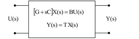
Figure 1: System model
Where G, C, B, T are coefficient matrices. All conductances and frequency-independent values arising in the MNA formulation are stored in matrix G, capacitor and inductor values which are frequency-dependent in matrix C. U(s) represents the input (voltage or current source), Y(s) represents the output variable (voltage/current). The unknown vector X(s) contains both voltage and current variables. MNA can handle all types of active and passive elements regarding a dynamic system. It is a very important property of MNA.
Taking into account the types of variables, the unknown vector is partitioned as follows.
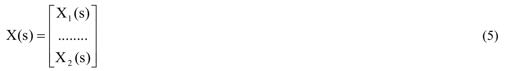
Here, X1(s) represents nodal voltage variables, X2(s) represents current variables related to independent and controlled voltage sources, inductors, short circuit elements, etc. If there are n nodes and m current variables in a dynamic circuit, X1(s) vector contains n-1 nodal voltage variables except a reference node (ground) and X2(s) vector contains m current variables. Thus, the unknown vector X(s) contains k=n-1+m variables.


From Eq. (3), X(s) is obtained as follows.


Eq. (9) are also expressed separately as follows.

The elements of X(s) vector in Eq. (9) or Eq. (10) are expressed in terms of the elements of W(s) vector and the input.
In the two ports circuit representation of Fig.2, the nodes of input port are 1, n and the nodes of output port are n-1, n-2. Node n is always taken as a reference node (ground,Un= 0)). Sometimes, the input and the output ports are connected to a common reference node, as in the illustrative examples. The voltage source (Ui(s)) in Fig.2 is a symbolic source to be used in obtaining the network functions.
In Fig.2, Ui(s)=U1(s) and Uo(s)=Un-2(s)-Un-1(s). That is, the input voltage of circuit (Ui) is always equal to the first nodal voltage (the first variable of system) in X1(s) vector, the output voltage of circuit (Uo) is always equal to the difference between the last two nodal voltages (the (n-2)th and (n-1)th variables of system) in X1(s) vector. In Eq. (9) or Eq.(10), W1(s)=1 because of U(s)=Ui(s) = U1(s). The input current (Ii(s)) is the source current.It is located in the last row of X2(s) or X(s) vector. That is, Ii(s)= Im(s). For the output current (Io(s)), the output port in Fig.2 must be terminated with any circuit element. For instance, the circuit in Fig.2 is terminated with a resistor.
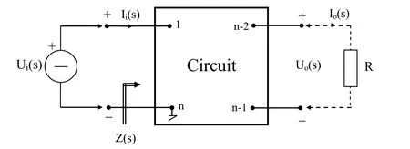
Figure 2: Two port circuit
In order to obtain the system equations, as a input, a symbolic current source (Ji(s)) can be also used. In this case, the structure of equations is similar to Eq. (9) or Eq. (10). Of course, the elements of W(s) vector will be different for every input (Ui(s) or Ji(s)).
The above expressions are given for the circuit having one input and one output in Fig.2.For the case of p inputs and q outputs, as in the circuit of Fig.3, the expressions can be generalized. In this case, the W(s) vector is of orderIn this paper, for one-input and one-output circuits, as in Fig.2, the network functions are expressed. For multi-input and multi-output circuits, similar expressions are valid.


Figure 3: Circuit with p inputs and q outputs
3 Network functions
Using Eq. (9) or Eq. (10), network functions and various domain responses related to any dynamic circuit can be expressed systematically in terms of the elements of W(s) vector.
3.1 Transfer functions
The transfer function (H(s)) is defined as the ratio of the output response to the input. It can be obtained by using Eq. (3) and Eq. (4).
From Eq. (3),

The output equation,

From Eq. (13), the transfer function is expressed in terms of the matrices of MNA system.

Eq. (14) is the general statement of transfer functions. There are four kinds of transfer functions regarding to input and output variables.
Voltage transfer function:

Current transfer function:

Transfer impedance function:
Transfer admittance function:

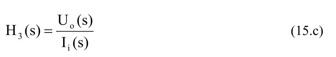
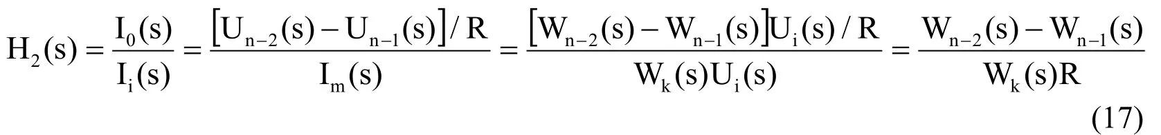
For obtaining the transfer functions, the voltage and current variables related to input and output ports are expressed in terms of the elements of created vector, W(s), and the source, according to Fig. 2 and Eq. (10). For the current transfer function (Eq.15.b) and transfer admittance function (Eq.15.d), the output port in Fig.2 must be terminated with any circuit element. Here, the expressions are given for the case terminated with a resistor,as in Fig. 2. But, the method is general and can be applied for any circuit element.
Voltage transfer function:

Current transfer function:
Transfer impedance function:

Transfer admittance function:

3.2 Input Impedance
The input impedance or driving-point impedance, Z(s), is expressed according to Fig.2.

The impedance relates the voltage and the current at input terminals. Ui(s) is the driving source and Ii(s) is the source current in Fig.2. The source current: Ii(s)=Im(s).

3.3 Frequency-domain response
For frequency response of system, We replace s by iω in Eq. (12), Eq. (13), Eqs.(16)-(19),Eq.(21), respectively.
4 Illustrative examples
We give two examples to show the proposed method related to obtaining the network functions.
Example 1: Consider the circuit in Fig. 4. The system equations, the transfer functions(Uo/Ui, Uo/Ii), and the input impedance of the circuit will be obtained. Element values are R1= R2=2Ω, C1= C2= 3F, L = 5H.
The input and output of the circuit has a common reference node (4). The circuit has n-1=3 nonreference nodes. Thus, in the MNA system, X1(s) vector contains 3 nodal voltage variables. The current variables in X2(s) vector are IL, Ii. Thus, in the circuit,k=n-1+m=5. The representation of voltage source (Ui), as an input, is used to obtain the network functions.

Figure 4: Circuit for Example 1
Nodal (main) equations in s-domain:

The overall equations constitute the MNA system (Eq.23). The output equation of system is given in Eq. (24). The system model containing both MNA equations and output equation can be given in matrix form, as in Fig.1.

The system model, Eq. (23) and Eq. (24), can be systematically obtained by inspection because of the advantages of MNA. By transforming the system model into t-domain, the transient-state and steady-state analysis for any input can be also obtained. By using this system model, the vector W(s) is created. Thus, the desired network functions in terms of the components of W(s) are calculated systematically.

Where,

As seen from Eq. (26), because Ui(s) is equal to U1(s), W1(s)=1.Transfer functions:
The desired transfer functions are obtained as follows. W3(a) Uo/Ui


Example 2: Consider the circuit in Fig. 5. The system equations, the voltage transfer function (Uo/Ui), and the input impedance of the circuit will be obtained. Element values are R1=4Ω, R2=5Ω, R3=2Ω, C1=1F, C2=2F.
Node p is chosen as a reference, Up=0. The voltage and current constraints of ideal Op-Amp are Ip=0, In=0, Up-Un=0. In the MNA system, X1(s) vector contains 3 nodal voltage variables (Ua, Ub, Uc). The current variable in X2(s) vector is Ii. Thus, in the circuit, k=n-1+m=4. The representation of voltage source (Ui), as an input, is used to obtain the network function and the input impedance.

Figure 5: Circuit for Example 2
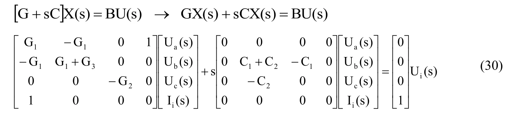
Nodal (main) equations in s-domain:

Additional equations:

The overall equations constitute the MNA system (Eq.30). The output equation of system is given in Eq. (31). The system model containing both MNA equations and output equation can be given in matrix form, as in Fig.1.

By using this system model, the vector W(s) is created. Thus, the desired network function and the input impedance are systematically calculated.

Where,

Voltage transfer function:
Input impedance:

5 Conclusions
The paper introduces a computer-based systematic matrix-based representation for the network functions of linear or linearized time-invariant dynamic circuits. The proposed method is based on the modified nodal approach, suitable for computer-aided analysis of active and passive circuits and creating a matrix formulation. The main contribution of the paper is that it gives a computer-based systematic formulation method in terms of the components of the created vector, W(s). Transfer functions and input impedances related to the examples show the efficiency of the approach.
The system equations and network functions can be obtained systematically by inspection.Therefore, for future work, a computer program about the network functions and frequency domain analysis of active and passive circuits can be written by using the presented method. Moreover, the noise analysis, one of the interesting applications of network analysis, can be also realized by this method.
Aguirre, I.; Carlosena, A. (2001): A symbolic method for network function approximation w ith order reduction, Int. Journal of Circuit Theory and Applications, vol.28, no.3, pp.313-318.
Djordjevic, S.; Petkovic, P.M. (2004): Generation of factorized symbolic network function by circuit topology reduction, IEEE 24thInt. Conf. on Microelectronics (MIEL).Serbia and Montenegro, pp.773-776.
Exposito, A.G.; Soler, A.B.; Macias, J. (2009): Efficient dominant eigensystem comput ation using nodal equations, Int. Journal of Circuit Theory and Applications, vol.37, no.1,pp.137-158.
Ho, C.W., et al. (1975): The modified nodal approach to network analysis, IEEE Trans.on Circuits and Systems, vol.22, no.6, pp.504-509.
Karina, V.; Rodriguez, Q.; Guillemin, F. (2016): Performance analysis of resource pooling for network function virtualization, 17thInt. Telecommunications Network Strategy and Planning Symp., Canada, pp.158-163.
Li, Y.; Phan, L.T.X.; Loo, B.T. (2016): Network functions virtualization with soft real-time guarantees, The 35th Annual IEEE Int. Conf. on Computer Communications, USA, pp.1-9.
Nedelea,L.; Topa, M.; Neag, M. (2003): Computer-aided network function approximation for multi criteria filter design, IEEE Int. Symposium on Signals, Circuits and Systems (SCS),Romania, pp.81-84.
Psychalinos, C. (2007): Realization of log-domain high-order transfer functions using first-order building blocks and complementary operators, Int. Journal of Circuit Theory and Applications, vol.35, no.1, pp.17-32.
Pierzchala, M.; Rodanski, B. (2001): Generation of sequential symbolic network functions for large-scale networks by circuit reduction to a two-port, IEEE Transaction on Circuits and Systems-I Fundamental Theory and Applications, vol.48, no.7, pp.906-909.
Raut, R. (2006): On the realization of current transfer function using voltage amplifiers,Int. Journal of Circuit Theory and Applications, vol.34, no.5, pp.583-589.
Reis, T. (2010): Circuit synthesis of passive descriptor systems-A modified nodal approach, Int. Journal of Circuit Theory and Applications, vol.38, no.1, pp.44-68.
Ruzhang, L.; Xiangdong, W.; Zhaoming, W.; Xiangfu, H. (1995): A new algorithm for generating symbolic network functions by computer, IEEE 4thInt. Conference on Solid-State and Integrated Circuit Technology, China, pp.349-351.
Sagbas, M.; Ayten U.E.; Sedef H. (2010): Current and voltage transfer function filters using a single active device, IET Circuits, Devices & Systems, vol.4, no.1, pp.78-86.
Shi, C.J.; Tan, X.D. (2001): Compact representation and efficient generation of sexpanded symbolic network functions for computer-aided analog circuit design, IEEE Transaction on Computer-Aided Design of Integrated Circuits and Systems, vol.20, no.7,pp.813-827.
Thomas, R.E.; Rosa, A.J. (2006): The analysis and design of linear circuits, John Wiley& Sons.
Topa, M.D.; Simon, E. (1996): Applications of symbolic network analysis, IEEE 3rdInt.Conference on Electronics, Circuits, and Systems (ICECS), Romania, pp.108-111.
Vlach, J.; Singhal, K. (1983): Computers methods for circuit analysis and design, Van Nostrand.
Wambacq, P.; Gielen, G.; Sansen, W. (1996): A new reliable approximation method for expanded symbolic network functions, IEEE Int. Symposium on Circuits and Systems(ISCAS), Atlanta, pp.584-587.
Yildiz, A.B. (2010): Modified Nodal Analysis-Based Determination of Transfer Functions for Multi-Inputs Multi-Outputs Linear Circuits, Automatika-Journal for Control, Measurement,Electronics, Computing and Communications, vol.51, no.4, pp.353-360.
Yuan, Y. (2000): On the periodicity of network functions of periodically switched linear and nonlinear circuits, IEEE Canadian Conference on Electrical and Computer Engineering, pp.574-577.
Yu, Q.; Sechen, C. (1996): A unified approach to the approximate symbolic analysis of large analog integrated circuits, IEEE Tran. on Circuits and Systems I: Fundamental Theory and Applications, vol.43, no.8, pp. 656-669.
Yoon, S.; Na, T.; Yoon, H.; Ryu, H.Y. (2016): Design and implementation of virtual network function development toolkit, Int. Conf. on Information and Communication Tech. Conv.(ICTC), S. Korea, pp.892-897.
杂志排行

Computer Modeling In Engineering&Sciences的其它文章
- A Dimension-Reduction Interval Analysis Method for Uncertain Problems
- Research on Instability Mechanism and Type of Ore Pillar based on the Fold Catastrophe Theory
- Numerical investigation of penetration in Ceramic/Aluminum targets using Smoothed particle hydrodynamics method and presenting a modified analytical model
- An Adaptive Load Stepping Algorithm for Path-Dependent Problems Based on Estimated Convergence Rates
- Axisymmetric Slow Motion of a Prolate Particle in a Circular Capillary with Slip Surfaces
- Performance of Compact Radial Basis Functions in the Direct Interpolation Boundary Element Method for Solving Potential Problems