Numerical study of the flow and dilution behaviors of round buoyant jet in counterflow*
2017-03-09MengGao高猛WenxinHuai槐文信YitianLi李义天WeijieWang王伟杰
Meng Gao (高猛), Wen-xin Huai (槐文信), Yi-tian Li (李义天), Wei-jie Wang (王伟杰)
State Key Laboratory of Water Resources and Hydropower Engineering Science, Wuhan University, Wuhan 430072, China, E-mail:gm60024@whu.edu.cn
(Received October 17, 2016, Revised December 9, 2016)
Numerical study of the flow and dilution behaviors of round buoyant jet in counterflow*
Meng Gao (高猛), Wen-xin Huai (槐文信), Yi-tian Li (李义天), Wei-jie Wang (王伟杰)
State Key Laboratory of Water Resources and Hydropower Engineering Science, Wuhan University, Wuhan 430072, China, E-mail:gm60024@whu.edu.cn
(Received October 17, 2016, Revised December 9, 2016)
Pollutants are usually discharged into the receiving water bodies in the form of a turbulent jet or plume, and the presence of a counterflow enhances the initial dilution of the jet effluent. To understand the behaviors of jets in actual situations, a round buoyant jet issued horizontally into a uniform counterflow is simulated for different combinations of densimetric Froude number and jet-to-current velocity ratio. A two-phase mixture model is used to simulate this flow, and the renormalization groupk-εmodel is used to address the flow turbulence. The inter-phase interactions are described in terms of the relative slip velocity between phases. The jet features, including the trajectory of the jet centerline and the decay of the centerline velocity and the concentration, are investigated. The length scale analysis reveals the relationships between the distance and the centerline dilutions, and different flow mechanisms are revealed before and after the penetration point.
Buoyant jet, counterflow, mixture model, velocity decay, concentration dilution
The wastewater from industrial areas and cities or the thermal effluents from the cooling systems of power plants are usually discharged into the receiving water bodies via outfalls in the form of turbulent jets or plumes. The behavior of these jets completely differs from that in a stagnant ambient water because the presence of a moving ambient water can significantly change their flow structure and mixing properties. When the jet and the main flow directions are opposite to each other, a turbulent jet is formed in the counterflow. The presence of a counterflow enhances the mixing efficiency of the jet, thereby making this flow configuration an interesting issue for many engineering applications, especially, for environmental engineering.
Some experimental studies examined the behavior of a non-buoyant jet in a counterflow using laserbased flow measurement techniques, including the laser-induced fluorescence (LIF) and the laser Doppler anemometry[1]. Numerical simulations were also performed to investigate turbulent round jets in a uniform counterflow[2]. Due to the merging of buoyant jets, the flow and mixing fields of these jets are generally complex and difficult to predict. Lee[3]investigated the global spreading patterns of a round buoyant jet in a counterflow by conducting LIF measurements in a laboratory. These measurements offer abundant information about the concentration field.
In this paper, a round buoyant jet in a uniform counterflow is simulated using a two-phase mixture model. Several flow cases with a densimetric Froude number (Fr)ranging from 3 to 10 and a velocity ratio (R)ranging from 5 to 15 are considered in the simulation, focusing on the central vertical plane, on which the jet behavior obviously changes along with the jet trajectory. The flow behaviors, including the jet centerline velocity and dilution, are investigated via a length scale analysis.
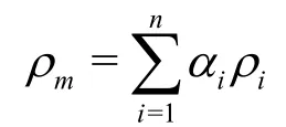
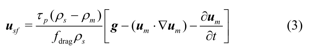
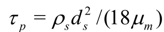
The simulation is performed using a two-phase mixture model. The wastewater jet flow is assumed tocomprise the water and the separate, interpenetrating particle phases.αsandαfdenote the volume fractions of the particle and fluid phases, respectively. The mixture model allows these two phases to move at different velocities with slip velocities. A Schiller-Naumann drag model is used to describe the interaction between these phases[4,5].
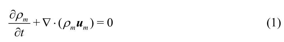
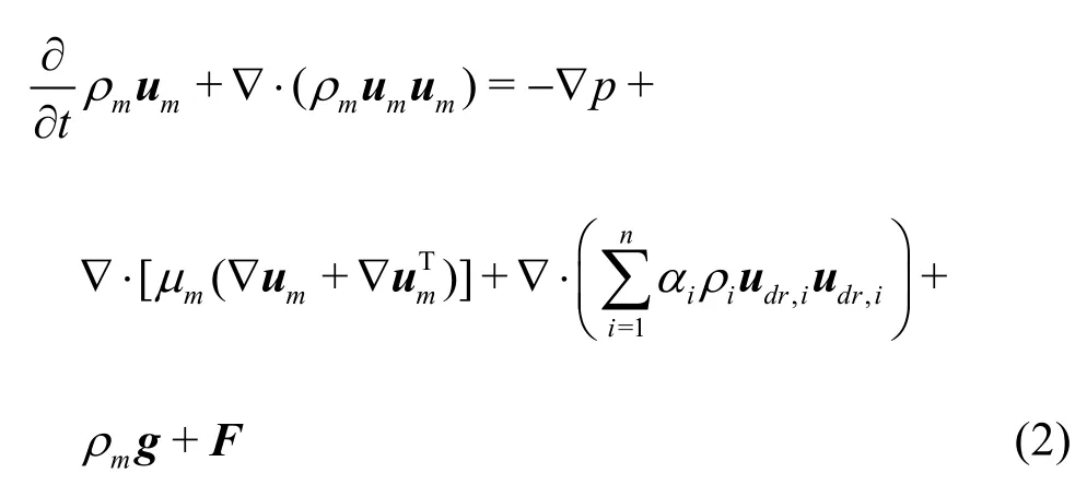
The continuity equation of the mixture takes the following form
drag 0.0183Re, whereReis the Reynolds number.
The renormalization groupk-εmodel is used to close the governing equations. The turbulent kinetic energykand its rate of dissipationεare expressed as follows
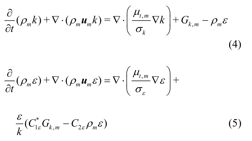
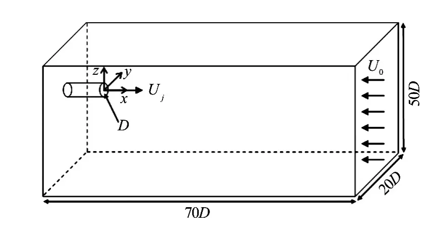
Fig.1 Schematic diagram of the flow configuration
A round buoyant jet with initial velocityUj, densityρ0, Reynolds numberRe0and nozzle diameterDis discharged into the ambient water with an infinite depth, velocityU0, and densityρa. The numerical domain has the dimension of 70D×20D× 50Din the axial (x), lateral (y), and vertical (z) directions, as shown in Fig.1.
Similar to previous experiments, salt water is used as the negatively buoyant jet effluent. The salt has a density of 1 035.1 kg/m3, while the water has a den-sity of 998.4 kg/m3. In the simulation, a negatively buoyant jet is formed, but the results could be interpreted as a positive buoyancy case by transforming the reference frame upside down[3].
The velocity inlet boundary condition is defined at the jet exit (x=0)and the counterflow inlet (x= 70D). The pressure outlet boundary conditions involve the specification of a static (gauge) pressure at the outlet boundary(x=−10D)and are used to model the flow exits. The rest of the domain is a wall with standard wall functions.
All governing equations are solved in a Cartesian coordinate system using the finite volume method. Pressure-velocity coupling is dealt with by using the SIMPLEC algorithm. The second order scheme is applied to discretize the diffusion and convection terms in the governing equations, and the QUICK scheme is applied to the volume fraction equation. The calculation is considered convergent when the residual is less than 10‒5for the governing equations.
The experiments were initially conducted by Lee in a laboratory flume. Based on the experimental data, 20 cases are selected withRranging from 5 to 15 andFrranging from 3 to 10. The experimental data and computational results are compared as shown in Fig.2. The numerical results for the jet centerline trajectories are similar to the experimental observations of Lee.
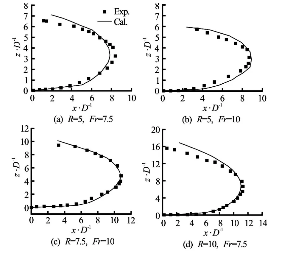
Fig.2 Comparison of jet centerline trajectories
Figure 2 shows that the jet penetrated into the counterflow primarily along the horizontal direction. The jet width is increased as a result of the interaction with the counterflow. Along with the decay of the jet velocity, the effect of buoyancy becomes obvious and is gradually increased along with the vertical rise of the jet. At the penetration point, the forward jet velocities are reduced to 0 and the counterflow velocity advects the buoyant jet effluent backward. In the backward flow region, the jet behaves as a buoyant line advected thermally backward by the counterflow.
Dimensional analysis yields the following general scaling laws for the buoyant jets in a uniform environment[6]:
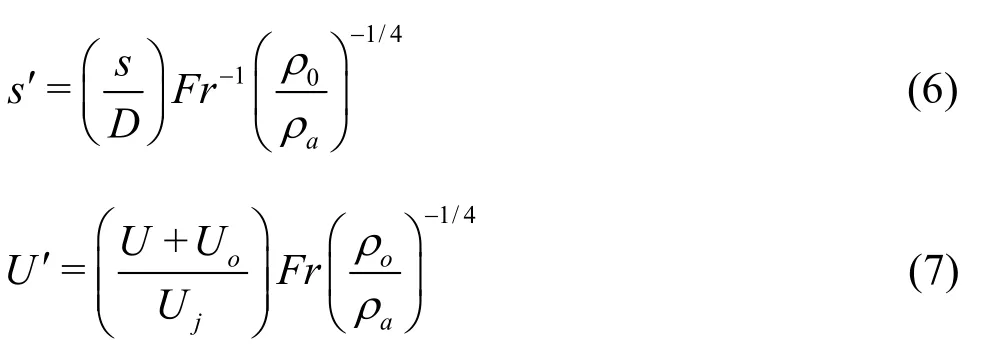
wheres′andU′represent the dimensionless lengths in the natural coordinate and dimensionless velocity, respectively.
Figure 3 shows the decay of the centerline velocity(U)normalized by Eq.(7) along the jet axial line. The centerline velocity remains unchanged for a certain distance near the jet exit when the buoyant jet penetrates forward into the counterflow. Afterward, the velocity begins to decay and converges to the penetration point. The rate of the velocity decay depends onR, instead ofFr. The centerline velocity decreases more rapidly asRincreases.
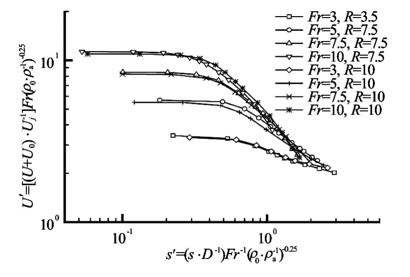
Fig.3 Non-dimensional centerline velocity decays along the axial line, based on simulated data (before the penetration point)
According to Knudsen[7], up to four asymptotic flow regions can exist in different parts of a buoyant jet in a counterflow. The four flow regions include the momentum-dominated near field (MDNF), the momentum-dominated far field (MDFF), the buoyancydominated near field (BDNF), and the buoyancydominated far field (BDFF).
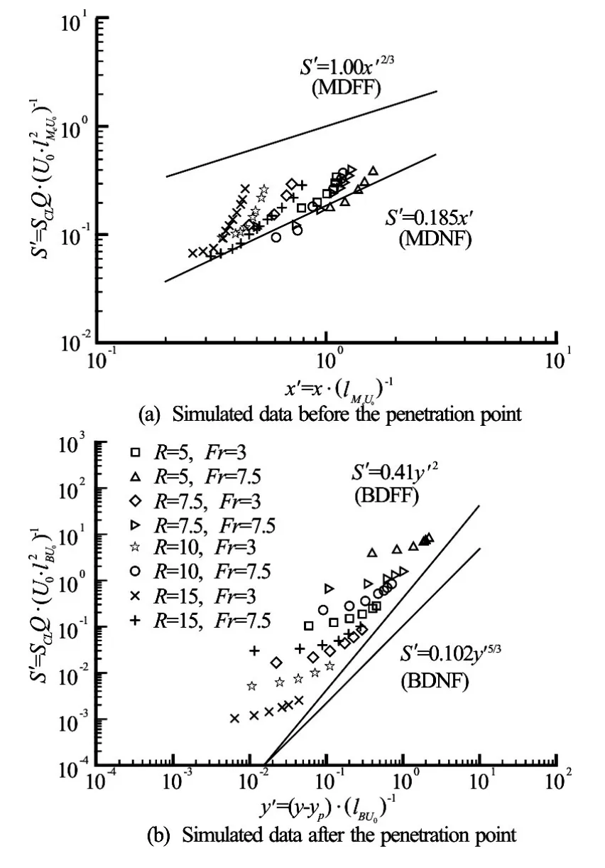
Fig.4 Jet centerline dilutions normalized by length scales
(1) In the region before the penetration point, all centerline dilutions data are initially dispersed for differentRvalues, but then collapsed and placed above and parallel to the asymptotic region for the MDNF. After the initial zone, the jet centerline dilution exhibits the behavior of the MDNF region with a dependence onx.The centerline dilutions before the penetration point do not reflect the features of the MDFF.
(2) Figure 4(b) shows that the minimum dilution data beyond the penetration point exhibit the characteristics of the BDFF. By observing the transition between regions in the centerline dilution, one can find that most of the jets in this study follow an MDNFBDFF sequence. After reaching the penetration point, nearly all jets transit into the BDFF.
The mixture two-phase model is used to simulate a buoyant jet in a counterflow. The simulation results are compared with the experimental data, with good agreements in most flow cases. The jet behaviors depend onRandFr. Two regions are divided by the penetration point. The flow in different regions of the jet is influenced by the momentum and the buoyancy in varying degrees.
The decay of the jet centerline velocity before the penetration point is analyzed against proper scaling parameters. The length scale analysis is applied to the centerline dilution data to explore the mixing and spreading mechanisms in different flow regions. Different flow mechanisms are revealed before and after the penetration point. All jets in the backward flow region beyond the penetration point exhibit the characteristics of the BDFF. This study sheds some light on the question how the combined action of the momentum and the buoyancy can determine the jet flow behavior.
[1] Lam K. M., Chan C. H. C. Time-averaged mixing behavior of circular jet in counterflow: Velocity and concentration measurements [J].Journal of Hydraulic Engineering, ASCE, 2002, 128(9): 861-865.
[2] Amamou A., Habli S., Saïd N. M. et al. Numerical study of turbulent round jet in a uniform counterflow using a second order Reynolds stress model [J].Journal of Hydro-Environment Research, 2015, 9(4): 482-495.
[3] Lee W. Y. Global behavior of a round buoyant jet in a counterflow [D]. Master Thesis, Hong Kong, China: University of Hong Kong, 2006.
[4] Belcaid A., Le Palec G., Draoui A. Numerical and experimental study of Boussinesq wall horizontal turbulent jet of fresh water in a static homogeneous environment of salt water [J].Journal of Hydrodynamics, 2015, 27(4): 604-615.
[5] Xue W., Huai W., Qian Z. et al. Numerical simulation of initial mixing of marine wastewater discharge from multiport diffusers [J].Engineering Computations, 2014, 31(7): 1379-1400.
[6] Chen C. J., Rodi W. Vertical turbulent buoyant jets: A review of experimental data [R]. NASA STI/Recon Technical Report A, 1980, 80.
[7] Knudsen M. Buoyant horizontal jets in an ambient flow [D]. Doctoral Thesis, Canterbury, New Zealand: University of Canterbury, 1988.
* Project supported by the National Natural Science Foundation of China (Grant Nos. 11672213, 51439007 and 11372232).
Biography:Meng Gao (1989- ), Male, Ph. D. Candidate
Wen-xin Huai, E-mail:wxhuai@whu.edu.cn
杂志排行

水动力学研究与进展 B辑的其它文章
- Large eddy simulation of free-surface flows*
- Effect of internal sloshing on added resistance of ship*
- Large eddy simulation of turbulent attached cavitating flow with special emphasis on large scale structures of the hydrofoil wake and turbulence-cavitation interactions*
- Assessment of the predictive capability of RANS models in simulating meandering open channel flows*
- The lubrication performance of water lubricated bearing with consideration of wall slip and inertial force*
- Ice accumulation and thickness distribution before inverted siphon*