The lubrication performance of water lubricated bearing with consideration of wall slip and inertial force*
2017-03-09ZhongliangXie解忠良NaTa塔娜ZhushiRao饶柱石
Zhong-liang Xie (解忠良), Na Ta (塔娜), Zhu-shi Rao (饶柱石)
Laboratory of Vibration, Shock and Noise, Shanghai Jiao Tong University, Shanghai 200240, China, E-mail: xiezlsj2011@sjtu.edu.cn
(Received July 30, 2015, Revised September 30, 2016)
The lubrication performance of water lubricated bearing with consideration of wall slip and inertial force*
Zhong-liang Xie (解忠良), Na Ta (塔娜), Zhu-shi Rao (饶柱石)
Laboratory of Vibration, Shock and Noise, Shanghai Jiao Tong University, Shanghai 200240, China, E-mail: xiezlsj2011@sjtu.edu.cn
(Received July 30, 2015, Revised September 30, 2016)
The lubrication mechanism and the performance parameters with consideration of wall slip and inertial force are studied in this paper. Based on the modified Reynolds equation, the finite difference method is used to study the lubrication mechanism and the performance. Effects of the wall slip and the inertial force on the performance parameters are obtained, and found in good agreement with the results of FLUENT. It is shown that the wall slip and the inertial force do not significantly change the distribution of the pressure, the load capacity and the friction force. The inertial force slightly increases the pressure and the load capacity by 1.2% and 4.8%, while the wall slip reduces them by 8.0% and 17.85%. The wall slip and the inertial force increase the friction by about 15.98%, 2.33%, respectively. Compared with the wall slip, the inertial force is smaller, but cannot be neglected.
Water lubricated bearing, wall slip, inertial force effect, lubrication performance
Introduction
The fluid flow boundary condition is one of the most important factors which determines the fluid hydrodynamic performance and characteristics. In the classical fluid mechanics and the lubrication theory the so-called “no slippage boundary conditions” are often used, namely, no wall slip occurs on the solidliquid interface, and the relative speed of motion between the fluid molecules on the solid surface and the solid interface is equal to zero. This hypothesis is verified by experiments in a macroscopic sense, and has been widely used in the theoretical analysis and the experimental researches. However, in recent years, with the development of the micro-nanometer science and technology, it is found that no slip boundary conditions are no longer valid under certain conditions. Boundary slip will occur in many instances[1,2], therefore affects the fluid behaviors and hydrodynamic cha-racteristics. The influence of the wall slip on the lubrication performance of the water lubricated bearing comes to be an important issue. For instance, Spikes et al.[3]analyzed the influence of slippage on the fluid dynamic behaviors with consideration of the wall slip only on the static slider surface. It is found that the bearing load capacity is exactly half of that with no slippage when the limiting shear stress is equal to zero, but the corresponding friction is reduced by several orders of magnitude.
Consequently, Spikes[4,5]proposed the thought of designing the bearing of a very low coefficient of friction, believing that the existence of the boundary slip would reduce the friction coefficient of the bearing surface, but might have a more complicated influence on the fluid hydrodynamic characteristics. Ma et al.[6,7]et al. studied the influence of the wall slip on the hydrodynamic lubrication performance of a twodimensional journal bearing (finite length journal bearing) based on the limiting shear stress model. Fortier et al.[8,9], Wang et al.[10]and Wu et al.[11]put forward the concept of heterogeneous slip, that is, the wall slip in different positions of the same solid surface of different slippage properties (i.e., with different limiting shear stresses). It goes beyond the framework of the classical lubrication theory[12], which holds that onlythe convergent gap can make the journal bearing generate the hydrodynamic pressure.
The water lubricated bearing is widely used in ships, water pumps and other mechanical systems for its various advantages, such as no pollution, wide source, safety and fire resistance. Its lubrication performance, reliability and safety help the safe and stable operation of the mechanical system. Therefore, the research and the improvement of the lubrication performance are of direct significance for the promotion and application of the water lubricated bearing.
Based on the modified Reynolds equation with consideration of both the wall slip and the inertial force, this paper investigates the lubrication mechanism of the water lubricated bearing through numerical methods, focusing on the pressure and thickness distributions as well as the variations of the bearing capacity and the friction force. The effects of the interface slip and the inertial force on the lubrication performance are analyzed, and the results are found to be consistent with the finite element analysis by the software FLUENT. This will help the structure design and optimization of the water lubricated bearing.
1. Derivation of modified Reynolds equation
1.1Theoretical basis of wall slip
It is shown[13,14]that the wall slip only occurs in the surface with smaller limiting shear stress when there exists a relative motion between two surfaces with different limiting shear stresses.
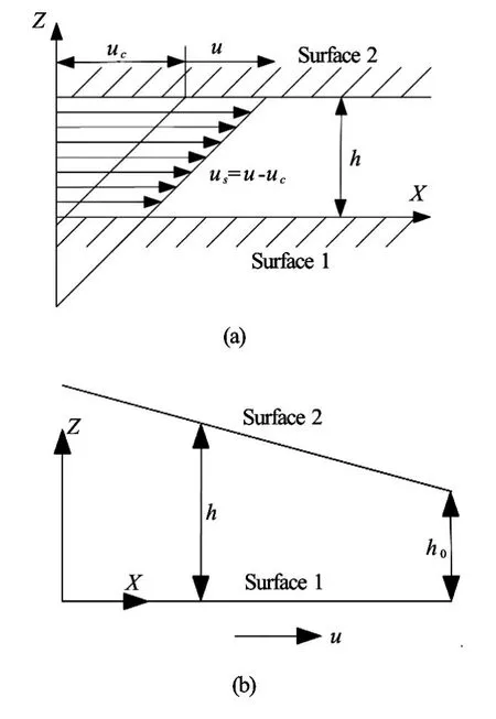
Fig.1 Schematic diagram of wall slip model
Figure 1(a) shows the schematic diagram of a wall slip model of the water lubricated bearing. Assuming that when the speed meets the criteriau=uc, Surface 1 just reaches the critical state of the interface slip, which means that the interface limiting shear stress is reached, correspondingly, the critical shear stressτcisτc=υ(uc/h)(υis the viscosity). With the increase of velocity on Surface 2, the wall slip starts to occur on Surface 1, the wall slip velocityusisus=u−uc,his the film thickness,ucthe critical slip velocity.
If there is no wall slip on any of the surfaces, the wall slip velocity is equal to zero, i.e.us=0. When the wall slip begins to occur, the wall slip velocity is equal to the difference between the velocity of Surface 2 and the critical slip velocity, i.e.,us=u−uc. It was proposed[15,16]that when the interface tension of the lubricant medium becomes larger than that of the friction pair material, then the interface slip is very likely to happen.
Table 1 shows the interfacial tension of commonly used materials. The interfacial tension of a water lubricated rubber bearing is much smaller, the adhesion fracture of water molecular bonds occurs more easily. Similarly, the wall slip may also exist on the solid-liquid interface of the water lubricated Teflon bearing. Therefore, the influence of the wall slip on the lubrication performance should be fully considered in the lubrication mechanism study for the water lubricated non-metallic or polymer friction pair material bearing.

Table 1 Interfacial tension of commonly used materials
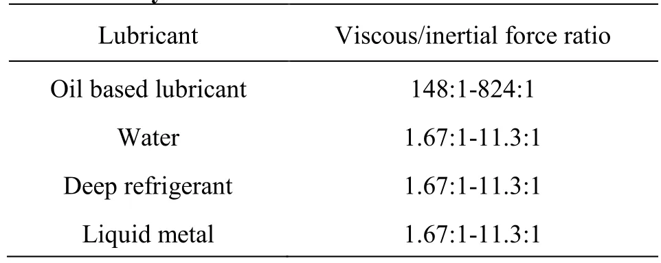
Table 2 The ratio of viscous force to inertial force of commonly used lubricants
1.2Theoretical basis of inertial force effect
Generally speaking, Reynolds number is very small for conventional oil based lubricants. Table 2 shows the ratio of the viscous force to the inertial force of commonly used lubricants. It is large for theconventional lubricants, so the inertial force effect is almost negligible. Under the same conditions, this ratio is relatively small for low viscosity lubricants, so the inertial force effect cannot be ignored. When the Reynolds number is close to the critical Reynolds number, the impact of the inertial force on the fluid flow will become more and more significant, the modified Reynolds equation with consideration of the inertial force can more properly describe the hydrodynamic characteristics of the water film.
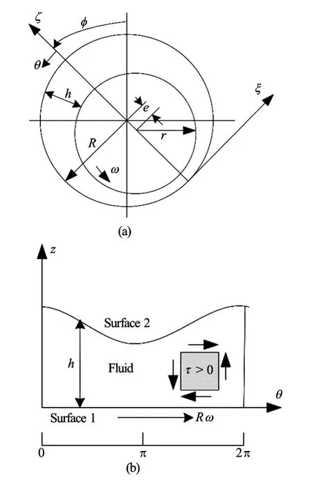
Fig.2 Schematic diagram of water lubricated bearing configuration
1.3Derivation of modified Reynolds equation
The modified Reynolds equation with consideration of both the wall slip and the inertial force is derived in the Cartesian coordinates based on the above theoretical analysis. The schematic diagram of the water lubricated bearing configuration is shown in Fig.2, and a simplified water lubricated bearing configuration in the Cartesian coordinates is shown in Fig.1(b). Surface 1 moves with speeduin the positivexdirection, while Surface 2 is stationary. The wall slip occurs on Surface 1, the critical limiting shear stress isτc, the critical slip velocity isuc. Assuming that the film thicknesshcan vary in thex,ydirections, but is small enough inzdirection so that the lubrication approximation is valid and the transient effect in the Navier-Stokes equations can be ignored. Thermal effects are not considered in the analysis, as the isothermal condition, and the viscosity and density of water regard as constants, without any changes with the temperature and pressure in the film thickness direction.
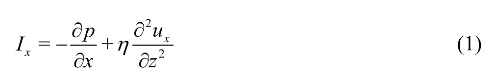
Using the above assumption, thex-component of the Navier-Stokes equation becomes
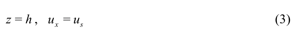
With the boundary conditions, on Surface1

and on Surface 2
Solving Eq.(1), subject to the boundary conditions Eqs.(2) and (3), we obtain the velocity component inxdirection

Similarly, the velocity component inydirection is

whereIx,Iyare the momentum components inx,ydirections,ux,uyare the velocity components inx,ydirections. The volumetric flow rate per unit length inxdirection is

Similarly, the volumetric flow rate per unit length inydirection is
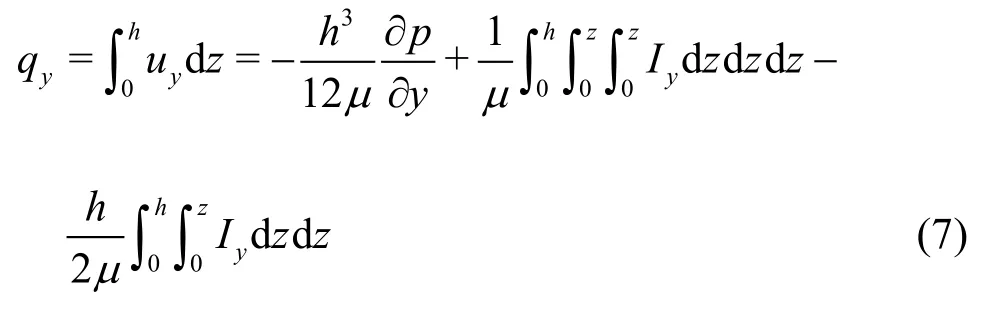
whereqx,qyare the volumetric flow rates inx,y-directions.
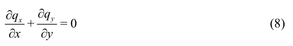
Conservation of mass requires

Inserting Eq.(6) and Eq.(7) into Eq.(8), we obtain

Equation (9) is made dimensionless by defining the following dimensionless variables. The resulting dimensionless modified Reynolds equation becomes
Linear combinations of these components represent modified Reynolds equations with different contributions as follows:
The bearing load capacity of the water film can be calculated as follows:

The friction force can be calculated as follows

1.4Numerical solution
These modified Reynolds equations are solved numerically by the finite difference method[12], with the discretization of the partial differential coefficients using the second order central difference. The natural rupture boundary conditions, namely, the Reynolds boundary conditions, are used here.
2. Results and discussions
Through analysis of the above theory, a finite length water lubricated bearing of angle of 360ois analyzed. Calculation starts from the thinnest area of the water film, i.e., assuming that the wall slip first occurs in the thinnest area of the film.
Fig.3 (Color online) The dimensionless pressure distributions with consideration of wall slip and inertial force of water film

Table 3 Characteristic parameters of circumferential pressure distribution of water film
2.1Pressure distribution
The dimensionless three-dimensional pressure distribution with consideration of the wall slip and the inertial force is shown in Fig.3(a). Figure 3(b) shows the dimensionless circumferential pressure distribution on the water film in four cases, whereθrepresents the circumferential coordinate,Lrepresents the axial coordinate. Pressure-I represents the result with consideration of the wall slip alone, pressure-II represents the result with consideration of both the wall slip and the inertial force, pressure-III represents the result without consideration of the wall slip and the inertial force effect, pressure-IV represents the result with consideration of the inertial force alone.
From Figs.3(a), 3(b) we can see that the pressure distribution shape is not significantly affected after the consideration of the wall slip and the inertial force. The inertial force slightly increases the peak pressure by about 1.2%, while the interface slip significantly decreases the peak pressure by about 8.0%.
Figure 3(b) shows the effect of the wall slip on the pressure boundary conditions, and also gives the rupture boundary of the water film. From Fig.3(b) we can obtain the maximum pressure and the rupture angle of the water film in four different cases. Characteristic parameters of the dimensionless circumferential pressure distribution of the water film are presented in Table 3. The water film rupture angle is about258owithout consideration of the wall slip and the inertial force, but the rupture angle increases to about 263owith consideration of the inertial force. Obviously, the pressure boundary expands outward and the entire water film lubrication region expands. Therefore, on one hand, the inertial force increases the film pressure peak, but on the other hand, it decreases the lubrication area and optimizes the lubrication state. To some extent, the inertial force effect is helpful for the lubrication performance of the bearing. The influence of the wall slip is just opposite.
The inertial force only influences the pressure values to a small margin, as compared with the influence of the wall slip, the influence of the inertial force on the water film hydrodynamic pressure is very limited, but it does influence the water film pressure boundary, the lubrication region and state. Furthermore, the calculation shows that, with the increase of the eccentri city ratio, the corresponding hydrodynamic pressure of the water film increases, and the wall slip effect becomes more significant. So is the reduction of the pressure peak, the maximum reduction amplitude may reach as high as 12%. And, the wall slip is first observed in the vicinity of the area of the minimum film thickness.
2.2Film thickness distributions
The dimensionless three-dimensional film thickness distribution with consideration of the wall slip and the inertial force is shown in Fig.4(a). Figure 4(b) shows the dimensionless circumferential film thickness distribution of the water film in four cases.
Fig.4 (Color online) The dimensionless film thickness of water film with consideration of wall slip and inertial force of water film
From Figs.4(a), 4(b) we can see that the film thickness distribution shape is not significantly affected after the consideration of both the wall slip and the inertial force. The wall slip slightly increases the film thickness values by about 1.8%, The film thickness curve reaches its minimum value at about 180.88owith consideration of the wall slip, but the value is180owithout its consideration. There is a deviation of0.88obetween these two cases. The esse-nce of the wall slip is the adhesive fracture or the fracture of molecular bonds. Therefore, the wall slip does not evidently change the viscosity and the density of the lubricant as well as the shape of the water film thickness. The wall slip firstly occurs in the maximum hydrodynamic pressure region, i.e. the area of the thinnest water film. Because under the same condition, the shear stress in the region of the thinnest film is the first to reach or even exceed the interface limiting shear stress, then the adhesion fracture happens, at the same time, the wall slip occurs.
The inertial force does not influence the film thickness values and the curve distribution trend. Essentially speaking, the inertial force is a conservative force and it does not work in the shaft rotation process. There is no energy transfer and no variation of the viscosity of lubricant. So the inertial force does not change the shape and the size of the film thickness distribution curve.
2.3Bearing load capacity
Figures 5(a), 5(b) show the dimensionless bearing load capacity and the friction force of the water film in four cases, respectively.εrepresents the eccentricity ratio of the bearing.
Fig.5 (Color online) The dimensionless bearing load capacity and friction force of the water film
From Fig.5(a) we can see that the bearing loading capacity increases along with the eccentricity, i.e., the larger the eccentricity, the larger the bearing loading capacity. The water film bearing loading capacity distribution is not significantly affected after consideration of both the wall slip and the inertial force. The inertial force slightly increases the bearing capacity, with the maximum increased amplitude of about 4.8%, while the wall slip evidently decreases the bearing capacity, with the reduced amplitude increasing along with the eccentricity, and with the maximum amplitude of about 17.85%. The bearing capacity with consideration of both the wall slip and the inertial force takes a value between that without consideration of the wall slip and the inertial force and that with consideration of the wall slip alone, but that value is much closer to the former. This fully illustrates the fact that compared to the wall slip, the influence of the inertial force on the lubrication performance is smaller, but cannot be neglected. From Fig.5(b) we can see that the curve shape is similar to that of the bearing load capacity. Mathematically speaking, compared to the wall slip, the influence of the inertial force on the friction force is smaller to some extent, but cannot be neglected.
2.4Finite element analysis of wall slip
A certain type of water lubricated bearing is analyzed by using the CFD software FLUNET. First we establish the water film model in the CAD software UG, then import it into the preprocessing module Gambit to mesh and fix the boundary conditions, and then import the mesh files into FLUENT for the finite element analysis. Table 4 shows the specific parameters of the water lubricated bearing. The water properties at 20oC as listed in Table 5 are employed.

Table 4 Basic parameters of the bearing
Generally speaking, the mesh plays an important role in the calculation. We have repeated the calculation several times with different meshes, to finally determine a proper mesh. We use a structural grid, for the mesh refinement and optimization. In the mesh, 5 divisions are used on the inlet and outlet surfaces along the radial direction, and 100 divisions are used for the edge on the inlet and outlet surfaces along the circumferential direction. The mesh is automatically divided along the axial water film direction. It is usually closely correlated with the length of the bearing. Altogether, there are about 17 952 nodes and 14 520 elements for the model (see in Figs.6(a), 6(b)).
Figure 7 shows the hydrodynamic water film model and the boundary conditions. The hydrodynamic flow in the wedge gap is considered to be incompressible, in a steady state and isothermal. In the preprocessing modelling, we only build the flow model between the bearing and the journal surface.

Table 5 Water properties at 20oC
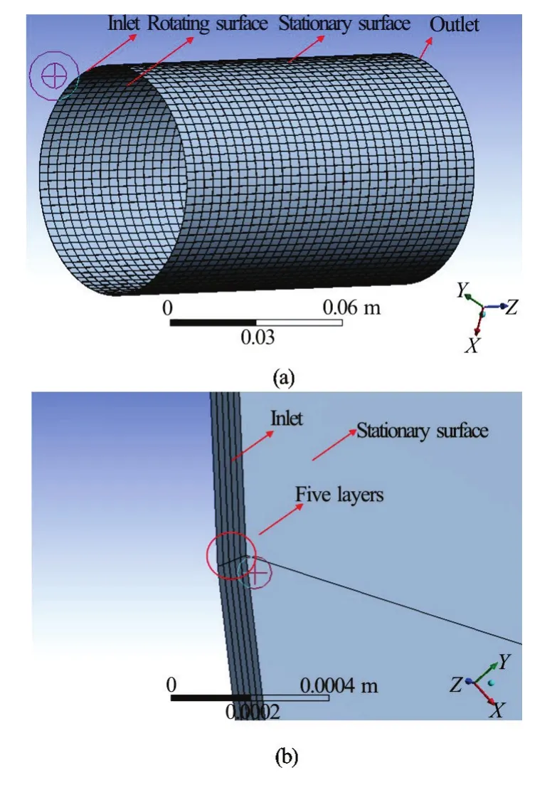
Fig.6 (Color online) Mesh models of the hydrodynamic water film

Fig.7 (Color online) Water film model and boundary conditions
The finite element software ANSYS 15.0 package is used in the simulation with the CFD models. Pro-processed models are incorporated into WORKBENCH. SIMPLEC algorithm is adopted in the calculation. The limiting shear stress of water is 1 806.5 Pa. The corresponding parameters are set in FLUENT and the simulations of two cases are conducted according to whether considering the interface slip or not. The pressure contours are obtained in the post processing module. Figure 8(a) shows the pressure contour of the water film without considering the wall slip. Figure 8(b) shows the pressure contour of the water film with consideration of the wall slip.
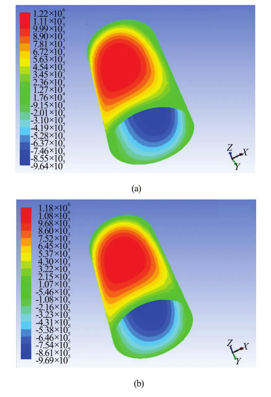
Fig.8 (Color online) The pressure contour of water film without/with consideration of wall slip
In order to further study the influence of the wall slip on the circumferential pressure distribution clearly, an iso-surface is plotted in the axial middle point of the film. The pressure data are calculated on the intersection of the iso-surface and the water film surface. Note that we ignore the negative pressure zone, and only consider the positive pressure area data in the investigation. Then the data are incorporated into the MATLAB to plot the pressure distribution curve[17,18].
Figure 9 hows the circumferential pressure distribution of the water film in four cases.Xaxis represents the circumferential coordinate of the bearing,Yaxis represents the water film pressure; P-I represents the result by the finite difference method without considering the wall slip, P-II represents the result by Fluent without considering the wall slip, P-III represents the result by the finite difference method with consideration of the wall slip, and P-IV represents the result by FLUENT with consideration of the wall slip.From Fig.9 we can see that the water film circumferential pressure increases nonlinearly and reaches its maximum value at about 0.063 m, then decreases rapidly to zero. With consideration of the wall slip, the peak pressure decreases visibly, with the maximum amplitude being reduced by about 3.4%. The wall slip first occurs in the vicinity of the region of the maximum hydrodynamic pressure for the shear stress here is the first to reach the interface limiting shear stress. The finite element simulation results are consistent with the theoretical results[19], with a very small deviation between them, which almost can be neglected. Consistency proves the correctness of the theoretical model[19].

Fig.9 (Color online) The circumferential pressure distribution
In the subsequent investigations[20,21], related experiments will be conducted systematically in order to obtain experimental results to verify the theory and the lubrication mechanism for the water lubricated plain journal bearing with consideration of wall slip[22].
3. Conclusions
This paper establishes a water lubricated bearing fluid dynamics model, derives the modified Reynolds equation with consideration of the wall slip and the inertial force. By numerical analysis methods, the influence of the wall slip and the inertial force on the lubrication performance of the water lubricated bearing is studied. The results are compared with those of the finite element software Fluent. The following conclusions are drawn:
(1) The wall slip and the inertial force have a certain impact on the hydrodynamic characteristics of the water film. The lubrication state and the lubrication performance can be more accurately described by the modified Reynolds equation with consideration of the wall slip and the inertial force.
(2) The wall slip slightly increases the film thickness, but does not change its shape. The inertial force has almost no effect on the film thickness distribution, its shape, value or size.
(3) The wall slip and the inertial force do not change the trend of the water film pressure, the bearing capacity and the friction force with eccentricity, but only change their values.
(4) Comparison between the finite element analysis by Fluent and the theoretical analysis is done for a certain actual water lubricated bearing with consideration of the wall slip. Simulation results are consistent with theoretical results.
[1] Kalin M., Polajnar M. The Effect of wetting and surface energy on the friction and slip in oil-lubricated contacts [J].Tribology letter, 2013, 52(2): 185-194.
[2] Neto C., Evans D. R., Bonaccurso E. et al. Boundary slip in Newtonian liquids: A review of experimental studies [J].Reports on Progress in Physics, 2005, 68(12): 28-59.
[3] Spikes H. A. The half-wetted bearing. Part 1: Extended Reynolds equation [J].Proceedings of the Institution of Mechanical Engineers, Part J: Journal of Engineering Tribology, 2003, 217(1): 1-14.
[4] Spikes H. A. The half-wetted bearing. Part 2: Potential application in low load contacts [J].Proceedings of the Institution of Mechanical Engineers, Part J: Journal of Engineering Tribology, 2003, 217(1): 15-26.
[5] Spikes H., Granick S. Equation for slip of simple liquids at smooth solid surfaces [J].Langmuir, 2003, 19(12): 5065-5071.
[6] Ma G. J., Wu C. W., Zhou P. Wall slip and hydrodynamics of two-dimensional journal bearing [J].Tribology International, 2007, 40(7): 1056-1066.
[7] Ma G. J., Wu C. W., Zhou P. Influence of wall slip on the hydrodynamic behavior of a two-dimensional slider bearing [J].Acta Mechanica Sinica, 2007, 23(6): 655-661.
[8] Fortier A. E., Salant R. F. Numerical analysis of a journal bearing with a heterogeneous slip/no-slip surface [J].Journal of Tribology, 2005, 127(4): 820-825.
[9] Salant R. F., Fortier A. E. Numerical analysis of a slider bearing with a heterogeneous slip/no-slip surface [J].Tribology Transaction, 2004, 47(3): 328-334.
[10] Wang L. L., Lu C. H., Wang M. The numerical analysis of the radial sleeve bearing with combined surface slip [J].Tribology International, 2012, 47: 100-104.
[11] Wu C. W., Wu C. D., Ma G. J. Low friction and high load support capacity of slider bearing with a mixed slip surface [J].Journal of Tribology, 2006, 128(4): 904-907.
[12] Szeri A. Z. Fluid film lubrication: Theory and design [M]. New York, USA: Cambridge University Press, 2005.
[13] Guo F., Wong P, Geng M. Occurrence of wall slip in elastohydrodynamic lubrication contacts [J].Tribology Letter, 2009, 34(2): 103-111.
[14] Wu C. W. Performance of hydrodynamic lubrication journal bearing with a slippage surface [J].Industrial Lubrication Tribology, 2008, 60(6): 293-298.
[15] Aurelian F., Patrick M., Mohamed H. Wall slip effects in (elasto) hydrodynamic journal bearings [J].Tribology Intertational, 2011, 44(7): 868-877.
[16] Hatzikiriakos S., Dealy J. Wall slip of molten high density polyethylene. I. Sliding plate rheometer studies [J].Journal of Rheology, 1991, 35(4): 497-523.
[17] Xie Z., Rao Z., Ta N. et al. Investigations on transitions of lubrication states for water lubricated bearing. Part I: Determination of friction coefficient and film thicknessratios [J].Industrial Lubrication and Tribology, 2016, 68(3): 404-415.
[18] Xie Z., Rao Z., Ta N. et al. Investigations on transitions of lubrication states for water lubricated bearing. Part II: Further insight into the film thickness ratio lambda [J].Industrial Lubrication and Tribology, 2016, 68(3): 416-429.
[19] Xie Z., Rao Z., Ta N. et al. Theoretical and experimental research on the friction coefficient of water lubricated bearing with consideration of wall slip effects [J].Mechanics and Industry, 2016, 17(1): 106-119.
[20] Yang J. Sharp interface direct forcing immersed boundary methods: A summary of some algorithms and applications [J].Journal of Hydrodynamics, 2016, 28(5): 713-730.
[21] Zhang X., Yin Z., Gao G. et al. Determination of stiffness coefficient of hydrodynamic water-lubricated plain journal bearings [J].Tribology International, 2015, 85: 37-47.
[22] Illner T., Bartel D., Deters L. Determination of the transition speed in journal bearing consideration of bearing deformation [J].Tribology Internaional, 2015, 82: 58-67.
* Biography:Zhong-liang Xie (1988-), Male, Ph. D. Candidate
Zhu-shi Rao, E-mail: zsrao@sjtu.edu.cn
杂志排行

水动力学研究与进展 B辑的其它文章
- Large eddy simulation of free-surface flows*
- Effect of internal sloshing on added resistance of ship*
- Large eddy simulation of turbulent attached cavitating flow with special emphasis on large scale structures of the hydrofoil wake and turbulence-cavitation interactions*
- Assessment of the predictive capability of RANS models in simulating meandering open channel flows*
- Ice accumulation and thickness distribution before inverted siphon*
- Lattice Boltzmann simulations of oscillating-grid turbulence*