基于 mimics 软件分析经颈椎前路椎弓根螺钉置钉技术的可行性
2016-11-24范国明龚遂良戴加平马巍
范国明 龚遂良 戴加平 马巍
基于 mimics 软件分析经颈椎前路椎弓根螺钉置钉技术的可行性
范国明龚遂良戴加平马巍
目的探讨 mimics 软件设计的经颈椎前路椎弓根螺钉理论置钉技术的可行性。方法2012 年1~4 月,我院门诊选择 30 例健康非脊柱疾病志愿者行 C2~7CT 轴向扫描,其中男 16 例,女 14 例,年龄 26~73 岁,平均 41.2 岁。用 dicom 格式导出,在个人计算机上用 mimics 软件对 C2~7各椎体进行蒙板、分割,行三维重建。利用 MEDcad 模块和测量模块,置入虚拟经颈椎前路椎弓根钉,然后测量其在椎体前缘的入口点位置及其与矢状面和水平面的夹角,确定经颈椎前路置入椎弓根螺钉是否存在可行性。结果C2椎弓根无法行前路手术。经颈椎前路椎弓根钉的投影点从 C3至 C7,并不在同一条直线上,而是形成一个 S 形的曲线,上往下逐渐从对侧转向同侧,前路椎弓根钉在椎体前壁上的投影点与椎体前表面上缘的垂直距离波动于 ( 6.56± 1.02 ) mm 与 ( 8.97±1.13 ) mm,与椎体前表面中心线的垂直距离,从 C3至 C7,波动于 ( 1.53±1.43 ) mm 与( 3.92±2.50 ) mm,左右两侧差异无统计学意义。结论除 C2外,经颈椎前路椎弓根螺钉按测量所得置入点及角度能实现置钉技术,临床操作可行,但因交叉碰撞,同一椎体不能实现双侧同时置入。
颈椎;椎弓根钉;图像处理,计算机辅助;软件;可行性研究
后路颈椎椎弓根钉在颈椎重建手术中能提供最坚强的固定。然而,某些病例需行多节段的前路减压。长节段植骨支撑或 cage 重建颈椎的生物力学性能很差,容易失败导致返修。而涉及多节段的手术或三柱损伤,需行前后联合入路固定或增加外固定方式处理,增加了手术风险、费用及感染几率,患者满意度降低。由于这些因素,需要增加前路重建手术的强度。Koller 等[1]首次尝试颈椎经前路椎弓根螺钉固定形态学可行性分析,但没有建立确切方便的置钉技术。Yukawa 等[2]利用现有的 AXIS 接骨板,利用C 型臂机进行颈椎经前路椎弓根螺钉的初步运用,将前路手术的优点和具备优秀生物力学特性的颈椎椎弓根内固定技术结合起来。2012 年 1~4 月,我院门诊选 30 例正常非脊柱疾病志愿人群,通过三维辅助软件 mimics 进行颈椎椎体重建,行虚拟置钉及测量后,分析经颈椎前路椎弓根螺钉置钉的可行性,同时确立可操作的临床置钉技术。现报告如下。
资料与方法
一、一般资料及数据获取
本组 30 例,其中男 16 例,女 14 例,年龄26~73 岁,平均 41.2 岁,告知本次研究的内容并签署知情同意书,所有志愿者均进行 C2~7CT ( Siemens,德国 ) 扫描,层厚 1.5 mm,层距 1.25 mm,螺距 0.75,导出 dicom 格式,刻入光盘。
二、数据重建
将所获得的数据导入个人计算机上 mimics 10.1软件 ( materialis,比利时 ),读取 CT 序列图像后,对颈椎进行阈值选取 ( threshold ),获得原始蒙板,然后经多层蒙板处理,三维重建,依次建立 C2~7椎体的三维图像,经光顺和三角面片修整后,获得完整的 C2~7的三维图像,予以保存。
三、虚拟置钉及数据测量
将获得的 C2~7三维图像进行最高透明显示,建立轮廓线,然后用 MEDcad 模块画出圆柱体,植入各椎体双侧椎弓根钉。椎弓根钉置入方式:将三维重建的椎体透明化,然后以椎体后壁为参照,使之垂直于屏幕,标准是椎体后壁上下缘重叠,侧方无倾斜,进行椎体约束,以椎管横距中心定位椎体中心线,以椎体前缘确立垂直于中心线的横垂线,然后旋转椎体,显示椎体矢状面像,再使椎体后壁垂直于屏幕下缘,后壁投影线再次重叠约束,做垂直于中心线的竖垂线,通过中心线、横垂线和竖垂线,两线确定一面的原理确定椎体的水平面、冠状面、矢状面,视窗将椎体设置成水平面,在该平面旋转椎体,使得椎弓根与屏幕下缘垂直,置钉,然后以屏幕为轴,旋转椎体,使得椎弓根孔道投影的上缘与椎体上方的距离和下缘与椎体下缘的距离相等,此时,该孔道中心认为是椎弓根的中心,调整椎弓根钉,使之前后中心重叠于椎弓根的中心,此时注意不能在水平面上有旋转,以防约束改变,造成置钉方法不统一。两侧方法一致。
通过 mimics 软件的测量模块建立测量文件,测量前路椎弓根螺钉的矢状面角、水平面角、投影点与椎体上缘的垂直距离及与椎体前缘中心线的垂直距离,确定置钉位置和角度。使用 Excel 软件记录各椎体相关数据。
四、统计学处理
采用 SPSS 14.0 软件进行统计学分析,确定各椎体颈椎前路椎弓根螺钉置钉点距离椎体前缘中心线及椎体上缘的垂直平均距离,各椎体椎弓根螺钉与水平面及矢状面的平均夹角。对左右两侧数据采用配对 t 检验,P<0.05 为差异有统计学意义。
表1 颈椎前路椎弓根钉入口与椎体上缘间距 (± s,mm )Tab.1 The distance from the entry point of the anterior cervical screw to the upper border line of the vertebra (± s, mm )

表1 颈椎前路椎弓根钉入口与椎体上缘间距 (± s,mm )Tab.1 The distance from the entry point of the anterior cervical screw to the upper border line of the vertebra (± s, mm )
椎体 右纵径 左纵径 t 值 P 值C3 6.56±1.02 6.58±1.06 -0.227 0.826 C4 6.94±1.15 7.12±1.08 -1.325 0.218 C5 7.13±1.30 6.91±1.23 1.110 0.296 C6 7.30±1.56 7.39±1.50 -1.891 0.091 C7 8.97±1.13 8.78±1.14 1.477 0.174
结 果
一、经颈椎前路椎弓根螺钉入口定位点
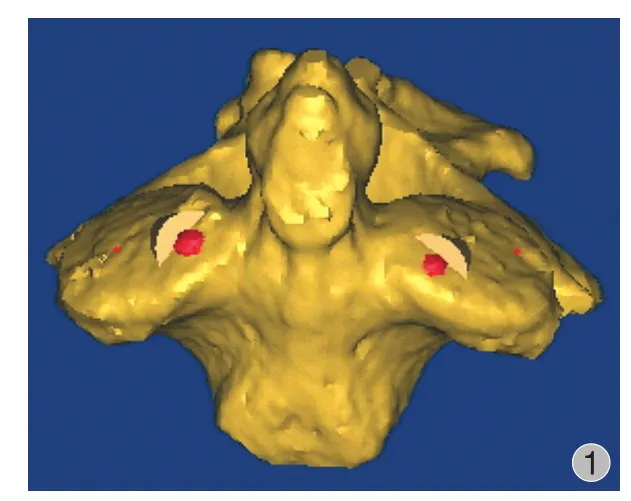
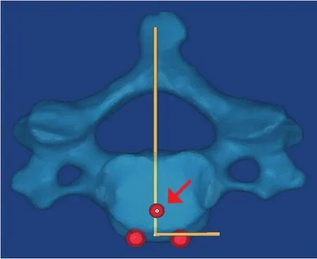
通过 mimics 软件分析,C2椎弓根钉从后路进入后将从 C2上关节突穿出,无法行颈椎前路椎弓根钉置入 ( 图 1 ),余椎体颈椎前路椎弓根钉均能实现前路置钉要求。颈椎前路椎弓根钉分布:C6以上在中心线对侧,C4位于对侧最偏外,C7在中心线同侧 ( 图 2 )。同时如表1 所示,颈椎椎弓根钉前缘入口点距离椎体上缘间距波动于 ( 6.56±1.02 ) mm 至( 8.97±1.13 ) mm 范围,往下逐渐有远离趋势,C7进钉点距离最远。C7右纵径为 ( 8.97±1.13 ) mm,左纵径为 ( 8.78±1.14 ) mm,左右两侧差异无统计学意义( P>0.05 )。颈椎椎弓根钉前缘入口点距离椎体前缘中线波动于 ( 1.53±1.43 ) mm 至 ( 4.19±1.84 ) mm 范围之间,左右两侧差异无统计学意义 ( P>0.05 )。C4进钉点在中线对侧最偏外,C6左右两侧基本重叠或接近于中线,C7在同侧最偏外。双侧椎弓根钉会出现交叉,除 C7椎体 ( 表2、图 3 )。

图 1 C2椎弓根投影点于上关节突表面穿出Fig.1 The projective point of the anterior screw of C2 was in the surface of the upper facet joint

图 2 颈椎前路椎弓根钉在椎体前缘表面投影点 a:显示的投影点为 S 形曲线;b:显示虚拟颈椎前路椎弓根钉透视图Fig.2 The projective point of the anterior pedicle screw in the anteriorce rvical surface a: The upper image showed the line was like a S shape; b: The right image showed the virtual perspective drawing of the anterior pedicle screw
二、经颈椎前路椎弓根螺钉平均矢状位及水平位夹角
颈椎经前路椎弓根螺钉从 C3至 C7椎弓根钉矢状面角度以 C3、C4及 C5角度最大,波动于 ( 46.59± 3.25 ) ° 至 ( 49.15±4.10 ) ° 之间,同时 C5椎体有趋势最大的表现。从 C6开始,矢状角减少,C7最小,左侧 ( 31.58±3.84 ) °,右侧 ( 31.93±5.80 ) °,左右两侧差异无统计学意义 ( P>0.05 )。颈椎经前路椎弓根螺钉从 C3至 C7椎弓根钉矢状面角度以 C3和 C6最小,C4、C5、C7趋势相近,除 C4外,左右两侧差异无统计学意义 ( 表3、4 )。
表2 颈椎前路椎弓根钉入口与椎体前缘中心线间距 (± s,mm )Tab.2 The distance from the entry point of the anterior cervical screw to the middle line of anterior surface of the vertebra (± s, mm )

表2 颈椎前路椎弓根钉入口与椎体前缘中心线间距 (± s,mm )Tab.2 The distance from the entry point of the anterior cervical screw to the middle line of anterior surface of the vertebra (± s, mm )
椎体 右纵径 左纵径 t 值 P 值C3 3.60±1.92 3.21±1.22 0.720 0.490 C4 4.19±1.84 3.05±1.76 1.527 0.161 C5 3.58±1.70 3.01±1.98 1.132 0.287 C6 1.53±1.43 2.41±1.90 -1.112 0.295 C7 3.53±2.87 3.92±2.50 -0.593 0.568
三、偏差因素
在设置椎体中线时,是以椎管横径中线作为标准的,但是实际上该中线比实际的略偏右 ( 图 4 ),所以,如表2 所示,入口点右侧比左侧有略偏大的趋势,平分中线后所得的左右入口点间距说明见表5。
表3 颈椎前路左右椎弓根钉矢状位变化趋势 (± s,° )Tab.3 Bilateral sagittal angles of the anterior cervical pedicle screw (± s, ° )

表3 颈椎前路左右椎弓根钉矢状位变化趋势 (± s,° )Tab.3 Bilateral sagittal angles of the anterior cervical pedicle screw (± s, ° )
椎体 左矢状角 右矢状角 t 值 P 值C3 46.59±3.25 46.97±4.81 -0.315 0.760 C4 47.84±4.02 49.44±4.20 -0.745 0.475 C5 48.62±3.60 49.15±4.10 -0.265 0.797 C6 42.23±6.02 43.81±4.06 -0.747 0.474 C7 31.58±3.84 31.93±5.80 -0.273 0.791
表4 颈椎前路左右椎弓根钉水平位变化趋势 (± s,° )Tab.4 Bilateral horizontal angles of the anterior cervical pedicle screws (± s, ° )

表4 颈椎前路左右椎弓根钉水平位变化趋势 (± s,° )Tab.4 Bilateral horizontal angles of the anterior cervical pedicle screws (± s, ° )
椎体 左水平角 右水平角 t 值 P 值C3 14.13±4.07 12.53±4.43 1.013 0.337 C4 21.83±4.62 18.41±4.94 3.136 0.012 C5 20.03±9.67 18.15±8.48 1.487 0.171 C6 16.84±4.36 16.25±5.65 0.573 0.581 C7 21.00±6.38 20.68±6.81 0.420 0.684
表5 颈椎前路左右椎弓根钉前缘投影点间距及平分间距 (± s,mm )Tab.5 The distance between bilateral entry points of the anterior cervical screws and the distance bisection (± s, mm )

表5 颈椎前路左右椎弓根钉前缘投影点间距及平分间距 (± s,mm )Tab.5 The distance between bilateral entry points of the anterior cervical screws and the distance bisection (± s, mm )
椎体 横向孔间距 平均横向孔间距C3 6.81±2.70 3.40±1.35 C4 7.23±2.72 3.62±1.36 C5 6.24±3.87 3.12±1.94 C6 2.73±3.33 1.37±1.66 C7 7.45±4.98 3.72±2.49

图 3 a~b:椎弓根钉交叉前面及上面观;c:螺钉方向与椎弓根呈一定角度,与传统方法有差异Fig.3 a - b: Cross of the screws in the anterior and upper perspective drawing; c: The difference of the direction of the screws compared with the traditional technology

图 4所指红点表示椎体中线,与椎管中线不在一条直线上,略偏左Fig.4 Red point nearindicated the middle line of the vertebra and it didn’t overlap with the yellow line which represented the middle line of the spinal canal
讨 论
在颈椎稳定性重建手术中,多节段的前路减压、长节段植骨或 cage 所重建颈椎的生物力学性能很差[3],多节段颈椎间盘切除融合术中不融合率高,长节段减压或椎体切除失败发生率 30%~100%[4-7]。有时也采用额外的后路固定或外固定方式[8-9]。但其增加了手术风险及感染率。类似的适应病例还包括单节段涉及三柱的骨折脱位、骨质疏松、肿瘤等需辅助后路加强固定[10],对这些特定病例,需要一种新的技术既满足单一切口减少创伤和感染,又能满足增加前路钉板抗拉强度的需求。结合前路手术优点和优秀的生物力学特性的新型经前路颈椎椎弓根固定技术应运而生。Koller 等[1]和 Yukawa 等[2]进行了不同的尝试。笔者利用 mimics 软件,将经前路椎弓钉置钉技术进行了具体化分析。
一、前路椎弓根钉在颈椎前缘表面投影的特点
在本研究中,通过 mimics 软件测定可以发现,C2无法实现从前路进行置钉,因为椎弓根投影点在上关节面 ( 图 1 ),后期测量中不再将其纳入。经前路颈椎椎弓根钉的投影点从 C3至 C7,并不在同一条直线上,而是形成一个 S 形的曲线。C6以上中心线对侧,C4对侧最偏外,C7在中心线同侧 ( 图 2 )。左右矢状角的特点是先增大后减小的趋势,C7最小,其次 C6,C4、C5最大,左右矢状径对比差异无统计学意义。双侧椎弓根钉除 C7外,存在交叉碰撞( 图 3 ),所以,目前的颈椎前路接骨板并不适应于行前路椎弓根钉的置入,或许在短节段固定的时候,可以用 AXIS 接骨板进行尝试。但无法实现双侧同时固定,可以考虑搭配椎体螺钉,在水平面上,C3的水平角最小,C6其次,C4、C5角度相似,左右两侧除 C4外,差异无统计学意义。C4显著性差异尚不能得到解释,可能与测量偏移有一定的关系。但原因可能并不一定如此,因为椎体并不是规则型的。前路椎弓根钉在椎体前壁上的投影点与椎体前表面上缘的垂直距离波动于 ( 6.56±1.02 ) mm 与( 8.97±1.13 ) mm,左右两侧不存在显著差异性,投影点至椎体前表面中心线的垂直距离,从 C3至 C7,波动于 ( 1.53±1.43 ) mm 与 ( 3.92±2.50 ) mm,左右两侧差异无统计学意义,但是尽管如此,从表2 中可以看出一个趋势,除 C6外,右横径大于左横径,C7在对侧,提示中心线有右偏的误差。从测量过程中可以看出,颈椎椎体并不是按照椎体中心线对称分布的,本研究在设立椎体中心的时候,以椎管横距的中心为椎体的中心线,该中心线 ( 垂线 ) 比实际椎体中线 ( 图 4 箭头所示红点位置 ) 要偏右。所以,在临床置钉的时候可能要把这个因素考虑进去,尽可能减少误差。需要说明的是中心线的设置是为了确定角度平面,对目前椎弓根钉角度和椎弓根钉投影点的孔间距是没有影响的。如果以椎体前缘中心线为参考平面,按孔间距平分值为参考进行置钉会更准确。
二、前路椎弓根钉虚拟置钉成功的关键要素及对临床置钉的参考
利用 mimics 软件进行虚拟设置经前路颈椎椎弓根螺钉成功的关键在于统一平面,对椎体进行确切约束,使椎弓根钉的置入在约束范围内进行,确保规则统一,因为设定椎弓根钉的置入方法不一致会导致结果的不一致。颈椎椎体形状不规则,从三维角度测得的椎弓根角度和二维平面测得的椎弓根角度在椎体空间发生位移时,会发生很大的改变,本研究在开始的时候采用三种测量方法进行比较。首先按传统方式进行椎弓根矢状面和冠状面投影,因无法准确设定参考平面而放弃,第二次采用试图使得椎弓根钉位置放置在椎弓根冠状面和矢状面均位于中心的位置。但实际上,在用 mimics 软件进行椎弓根中心线设置时,发现椎弓根通道中心表现为多阶位曲线形。所以,要把椎弓根钉准确打在所有的中心线上,不是一件很现实的事情。所以,本研究最后建立的置钉标准采用椎弓钉孔道透视,这可能与后路椎弓根钉置入有一定的差异,如图 3b 显示,但这是简单和安全的方法。首先将椎弓根投影竖直,垂直于屏幕下缘,此时椎体后方上下缘重叠,以此进行约束,然后在此基础上旋转椎体,逐渐使得椎弓根孔道投影的上缘与椎体上方的距离和下缘与椎体下缘的距离相等,此时,该孔道中心认为是椎弓根的中心,打入的椎弓根钉的前后中心重叠。这样建立的优点是:一是有固定的约束,使所有的经前路椎弓根钉的置入方法存在一致性,不会因为平面的不确定性而导致结果偏离过度。重复性高,简单方便。二是该设置方法同样适用于临床置钉。如前所述的 mimics 下椎弓根钉透视下置钉似乎描述烦琐,但这是为了研究的严谨需要,提供确切的约束,便于测量在统一的标准下进行,在临床上置入前路椎弓钉的时候,只要将 C 型臂机旋转,显示颈椎椎弓根通道的投影,同时保持投影上缘与椎体上缘和投影下缘与椎体下缘的距离相一致,置入椎弓根钉垂直于投影中心即可,安全性高。Yukawa 等[2]利用此法置钉仅发生 1 枚螺钉穿破,尽管如此,前路椎弓根钉透视法需要在熟悉颈椎解剖的基础上进行,要慎重选择适应病例。随着设备的进步,导航也可以作为一种方案[11]。
三、Mimics 软件进行虚拟置钉的可信性
利用 mimics 软件进行前路椎弓根钉的基础研究涉及一个与实物比较是否可信的问题。本研究为角度和距离的测定。纳入研究范围样本是通过 CT 扫描后重建的三维模型,虽然表面处理上和实物存在一定的差异性,但角度不存在扭曲现象,而且属于CT 的扫描定位,模型空间结构的分布与实物存在一致性,本研究的测量首先是角度的分析,然后根据空间结构确定测量的点,而不是在表面上直接画点进行常规测量,所以结果是可信的。目前,有大量的研究采用 mimics 软件建立颈椎椎体进行有限元分析和临床手术操作[12],说明大家对其可信度有了共识。其次,通过三维重建后的颈椎椎体,可以通过将椎体透明化,建立测量标准的时候可以通过椎体后壁投影重叠的方法建立固定的约束,使得测量方法标准化,比实物的测量更加准确。再次,在置入椎弓根钉的时候,通过孔道透视的特性,将置钉位置一致化,更贴近于临床。还有一点,可以将置入钉的直径随意更改,直至穿破椎弓根,可以确定钉的大小,同时不会产生像尸体一样的浪费,而且可以多次反复测定,既安全又便宜。需要提出的是,经前路钛板融合手术仍然是处理颈椎疾病的经典手段,经前路椎弓根钉系统存在一定的手术适应证,具有较高的风险,mimics 软件模拟了手术方式,具有参考价值,在临床上还是需要严格把控适应证和全面做好术前计划。
[1] Koller H, Hempfing A, Acosta F, et al. Cervical anterior transpedicular screw fixation. Part I: Study on morphological feasibility, indications, and technical prerequisites. Eur Spine J, 2008, 17(4):523-538.
[2] Yukawa Y, Kato F, Ito K, et al. Anterior cervical pedicle screw and plate fixation using fluoroscope-assisted pedicle axis view imaging: a preliminary report of a new cervical reconstruction technique. Eur Spine J, 2009, 18(6):911-916.
[3] Singh K, Vaccaro AR, Kim J, et al. Enhancement of stability following anterior cervical corpectomy: a biomechanical study. Spine, 2004, 29(8):845-849.
[4] Lowery GL, McDonough RF. The significance of hardware failure in anterior cervical plate fixation. Patients with 2- to 7-year follow-up. Spine, 1998, 23(2):181-186.
[5] Sasso RC, Ruggiero RA Jr, Reilly TM, et al. Early reconstruction failures after multilevel cervical corpectomy. Spine, 2003, 28(2):140-142.
[6] Schmidt R, Wilke HJ, Claes L, et al. Pedicle screws enhance primary stability in multilevel cervical corpectomies: biomechanical in vitro comparison of different implants including constrained and nonconstrained posterior instumentations. Spine, 2003, 28(16):1821-1828.
[7] Vaccaro AR, Falatyn SP, Scuderi GJ, et al. Early failure of long segment anterior cervical plate fixation. J Spinal Disord, 1998, 11(5):410-415.
[8] Swank ML, Sutterlin CE 3rd, Bossons CR, et al. Rigid internal fixation with lateral mass plates in multilevel anterior and posterior reconstruction of the cervical spine. Spine, 1997, 22(3):274-282.
[9] Ulrich C, Arand M, Nothwang J. Internal fixation on the lower cervical spine--biomechanics and clinical practice of procedures and implants. Eur Spine J, 2001, 10(2):88-100.
[10] Zhao LJ, Xu RM, Jiang WY, et al. A new technique for anterior cervical pedicle screw implantation. Orthop Surg, 2011, 3(3):193-198.
[11] Bredow J, Meyer C, Scheyerer MJ, et al. Accuracy of 3D fluoroscopy-navigated anterior transpedicular screw insertion in the cervical spine: an experimental study. Eur Spine J, 2016, 25(6):1683-1689.
[12] 肖进, 尹庆水, 张美超, 等. Mimics软件重建脊柱三维骨骼数据基础上快速成型的脊柱畸形模型. 中国组织工程研究, 2008, 12(35):6835-6838.
( 本文编辑:王萌 )
The feasibility of anterior cervical pedicle screw fixation technique by using Mimics software
FAN Guo-ming, GONG Sui-liang, DAI Jia-ping, MA Wei. Department of Orthopedics, the second Hospital of Jiaxing City, Jiaxing, Zhejiang, 314000, PRC Corresponding author: GONG Sui-liang, Email: fgmmail_cn@163.com
Objective To explore the feasibility of anterior cervical pedicle screw fixation technique by using Mimics software. Methods A total of 30 healthy volunteers ( 16 males and 14 females ), whose mean age was 41.2 years ( range: 26 - 73 years ), were enrolled in this study from January to April 2012 in the out-patient service. All the patients2to C7. The images were inputted into the computer in DICOM format. Mask, division and 3-dimensional reconstruction were performed for C2-7by using Mimics software. MEDcad module and measurement module were used to insert the anterior pedicle screw, and then the anterior pedicle screw insertion position in the anterior cervical surface was recorded. The angles between the anterior pedicle screw and the vertebral sagittal / horizontal plane were measured. The feasibility of anterior cervical pedicle screw fixation technique was analyzed by using Mimics software based on these data. Results The anterior insertion of pedicle screw guided by Mimics software for C2failed. The line of anterior cervical insert point was S-shaped, which was located from heterolateral side to ipsilateral side gradually from C3to C7. The vertical distance from the subpoint of pedicle screw insertion to the edge of the upper vertebral edge was from ( 6.56 ± 1.02 ) mm to ( 8.97 ± 1.13 ) mm. The vertical distance from the subpoint to the center line of the anterior vertebral surface was from ( 1.53 ± 1.43 ) mm to ( 3.92 ± 2.50 ) mm. No statistically significant differences were found between the 2 sides ( P < 0.05 ). Conclusions The insertion of pedicle screw guided by Mimics software from anterior cervical vertebra can be performed successfully except C2. But bilateral placement of the anterior pedicle screws in the same cervical vertebra can’t be achieved because of the intersection of the 2 screws.
the CT scan in the axial direction from C
Cervical vertebrae; Pedicle screws; Image processing, computer-assisted; Software; Feasibility studies
10.3969/j.issn.2095-252X.2016.11.016
R681.5, R687.3
314000 浙江,嘉兴市第二医院骨科
龚遂良,Email: fgmmail_cn@163.com
2016-04-09 )
