Optimal terminal guidance for exoatmospheric interception
2016-11-24YuWenbinChenWanchunYangLiangLiuXiaomingZhouHao
Yu Wenbin,Chen Wanchun,Yang Liang,Liu Xiaoming,Zhou Hao
School of Astronautics,Beihang University,Beijing 100083,China
Optimal terminal guidance for exoatmospheric interception
Yu Wenbin,Chen Wanchun,Yang Liang*,Liu Xiaoming,Zhou Hao
School of Astronautics,Beihang University,Beijing 100083,China
In this study,two optimal terminal guidance(OTG)laws,one of which takes into account the final velocity vector constraint,are developed for exoatmospheric interception using optimal control theory.In exoatmospheric interception,because the proposed guidance laws givefull consideration to the effect of gravity,they consume much less fuel than the traditional guidance laws while requiring a light computational load.In the development of the guidance laws,a unified optimal guidance problem is put forward,where the final velocity vector constraint can be considered or neglected by properly adjusting a parameter in the cost function.To make this problem analytically solvable,a linear model is used to approximate the gravity difference,the difference of the gravitational accelerations of the target and interceptor.Additionally,an example is provided to show that some achievements of this study can be used to significantly improve thefuel efficiency of the pulsed guidance employed by the interceptor whose divert thrust level is fixed.
1.Introduction
As the maximum speed of intercontinental ballistic missile(ICBM)is greater than 7 km/s and sometimes its apogee altitude can be up to 2000 km,currently only the ground-based midcourse defense(GMD)system equipped with groundbased interceptor(GBI)missile has the capability of intercepting ICBM.Theflight of GBI generally has three phases:boost,coast,and terminal guidance phases.After launch,the booster tries to put its warhead,which is commonly called kinetic kill vehicle(KKV)and destroys its intended target by direct collision,on a collision course,which means that if the KKV and target are only governed by gravity,the KKV can just hit the target directly.After the booster is turned of f,the KKV is separated from the booster and enters the coast phase in which the KKV flies to the predicted intercept point(PIP)without control.When the distance between the KKV and target reduces to a specified value,the terminal guidance phase begins.At this phase,the KKV uses the divert thrusters to per form lateral maneuvers in order to eliminate the PIP error.When these thrusters work,they consume much fuel.There fore,one main concern of designing the terminal guidance law is to minimize the maneuvering energy so as to savefuel.Additionally,sometimes it is desired that the KKV collides head-on with the target to increase the chances of success.There fore,the paper is aimed at designing two fuel-saving terminal guidance laws for exoatmospheric interception,one of which further considers thefinal velocity vector constraint.
The most widely used guidance law is proportional navigation(PN)because of its simplicity,effectiveness,and ease of implementation.1Yuan first put forward the basic principle of PN:2if the interceptor turns at a rate proportional to that of the line of sight(LOS),the interceptor can successfully hit the target travelling in uniform linear motion,and the angular velocity of the LOS will become zero finally.Adler extended PN to a 3D one using the tool of solid geometry.3Bryson and Ho demonstrated the optimality of PN.4Zarchan evaluated the performance of PN thoroughly and deeply.1In Refs.5–11,the variants of PN and their closed form solutions were presented.Graber developed the so-called augmented proportional navigation(APN)by adding an extra term to PN to account for the constant maneuvering acceleration of target.12In Ref.13,the guidance law considering the response lags was presented.Turetsky and Shinar proposed the guidance laws based on pursuit-evasion game formulations.14Ge et al.developed a head-pursuit guidance law for 3D hypervelocity interception using Lyapunov stability theory.15
For some special missions,the guidance laws capable of shaping trajectory are needed.These guidance laws are collectively referred to as trajectory shaping guidance(TSG).Cherry proposed a simple and effective TSG,called explicit guidance(E Guidance), for the first time by assuming that the commanded acceleration is a polynomial function of time.16E Guidance can be treated as an extension of PN because its expression consists of two terms:one is PN used to steer missile to destination,the other is used to control the final velocity vector.Ohlmeyer and Phillips obtained a series of the E Guidance coefficients by solving an optimal control problem with time-to-go weighted cost function.17Yu and Chen obtained the generalized closed form solutions of E Guidance where the closing speed can be an arbitrary positivefunction of time.18Further,by analyzing these generalized solutions,the stability domain of the guidance coefficients was obtained,in which E Guidance is stable and the commanded accelerations tend to be zero finally.Wang et al.improved E Guidance by considering the constant maneuvering acceleration of target.19In Refs.20–24,other types of TSG were presented.Yu and Chen proposed a novel guidance law for guiding missile against a maneuvering target while satisfying a circular no-fly-zone constraint.7In this guidance law,the real space is distorted such that the boundary of the no fly zone becomes a straight line,and then PN is used to steer the missile to the virtual target in the distorted space.
The widely-used terminal guidance laws for exoatmospheric interception are PN,APN,and predictive guidance(PG).Here,PG1is a guidance law that conducts the trajectory simulation once in each guidance cycle to predict the zero-effort miss(ZEM),and then uses the predicted ZEM to generate acceleration command.Zarchan evaluated their performance.1Simulation results show that PG consumes the least fuel because PG uses the accurate gravity model,but requires the heaviest computational load due to the real-time onboard trajectory simulations.PN and APN cause the interceptor to per form unnecessary maneuvers even if the interceptor has already been on a collision course.This is because they use the inaccurate gravity models:PN implies that the gravity difference is zero,whereas APN assumes that the gravity difference is constant.Simulation results show that the amount of the wasted fuel of APN is about half that of PN.
In this paper,two optimal terminal guidance(OTG)laws are developed for exoatmospheric interception using the optimal control theory:one considers the final velocity vector constraint,whereas the other does not consider it.Because the developed guidance laws evaluate the effect of gravity more accurately and need not conduct any onboard trajectory simulation,they almost consume as littlefuel as PG while having a light computational load.In the development of the OTG laws,a unified optimal guidance problem is put forward,of which the developed guidance laws are the two special solutions.Because the real gravity is a complex nonlinear function of position,it is impossible to obtain the exact analytical solutions of the problem.However,by observing the simulation trials,it can befound that the gravity difference almost varies linearly with time.There fore,the problem is made analytically solvable by the innovative use of a linear gravity difference model.Additionally,as the angular velocity of LOS can be measured by seeker directly,the OTG laws are re formulated in terms of the angular velocity of LOS using a novel 3D trans formation method based on vector operations,which considers the effect of gravity difference.
To implement the OTG laws,the position in formation is needed.However,the onboard infrared seeker can only provide the LOS orientation in formation and has a limited detection distance.Thus,in practice,the in formation on the states of motion is mainly provided by the external detection system such as X-band radar.When the interceptor gets close enough to the target,the infrared seeker becomes activated,and the data detected by the infrared seeker and external detection system arefused by Kalman filter to improve the accuracy of data.
It should be mentioned that some kinds of KKV cannot be throttled.For these KKVs,every time the thruster is turned on,the thrust will reach a fixed level and cannot be adjusted.In such a case,the pulsed guidance laws1,25,26are commonly employed,which use the predicted ZEM to determine the duration time of thrust.However,these guidance laws neglect the effect of gravity when predicting the ZEM.There fore,they will also result in a great waste of fuel in the long-range exoatmospheric interception.In fact,the formula of predicting ZEM proposed in this paper can be applied to the pulsed guidance laws.In Section 6.3,an example is given to demonstrate that this can significantly improve the fuel efficiency of the pulsed guidance laws.
2.Equations of motion
Fig.1 depicts the 3D engagement geometry outside the atmosphere of Earth.In this figure,the center of Earth is assumed to be stationary in the inertial space.An inertial frame of reference with origin at the center of Earth is created and called frame FE.As the engagement is outside the atmosphere,the interceptor missile uses the divert thrusters to per form lateral maneuvers where the thrust acceleration vector is denoted as aM= [aMx,aMy,aMz]T.The target is only governed by gravity and thus flies ballistically.In frame FE,the position vectors of the interceptor missile and targetare denoted as XM= [xM,yM,zM]Tand XT= [xT,yT,zT]Trespectively,their velocity vectors are denoted as VM= [VMx,VMy,VMz]Tand VT= [VTx,VTy,VTz]Trespectively,and their gravitational acceleration vectors are denoted as gMand gTrespectively.
Fig.1 Exoatmospheric interception geometry.
The equations of motion are

where μ is a constant of about 3.96272 × 10¹⁴m3/s2,and the symbol‘|·|”means the Euclidean norm of vector.
3.Optimal guidance problem
To develop the fuel-efficient guidance laws for exoatmospheric interception,the optimal guidance problem is posed where the cost function is

Here,k is a constant.tfrepresents the end time or flight time and will be discussed in detail in Section 5.tgo=tf-t is the time to go.XTM=XT-XMand VTM=VT-VMare the position and velocity vectors of the target relative to the missile,respectively.XTMfis the final value of XTM,and Eq.(9)makes the missile collide with the target.VTMfis the final value of VTM.is the desired value of VTMf.gTM=gT-gMis the gravity difference.
The cost function is designed with specific purposes.The first term on the right side of Eq.(6)is proposed for achieving the desired final velocity vector.In this term,the parameter k is used to adjust the contribution of VTMfto the cost function.After obtaining the general analytical solution of the optimal guidance problem,if one lets k=0,the guidance law without constraint on VTMfcan be obtained,but if one lets k go to in finity,the guidance law will be obtained,which makes the missile collide with its target while satisfying VTMf=The second term on the right side of Eq.(6)comes from Ref.17and is used to minimize the lateral divert requirement so as to savefuel.In this term,as t goes to tf,the weighttends to in finity.This makes aMconverge to zero finally,and greater exponent n tends to accelerate the convergence speed.It is emphasized again that different from the previous studies4,12,17,19,the effect of the gravity difference,which varies with position,is considered here.Thus,the proposed guidance laws require much less fuel than the traditional ones in exoatmospheric interception.
4.Optimal terminal guidance laws
As gTMis a complex nonlinear vector function of position,the analytical solution of the posed optimal guidance problem cannot be obtained.However,by observing the simulation trials where both the missile and target are only governed by gravity,it can befound that if the missile is just on a collision course,gTMvaries almost linearly with time,and at the collision point,there is gTM=0.As an example,one of these simulation trials is presented in Figs.2 and 3.Here,Fig.2 shows the trajectories of the missile and target,and Fig.3 shows the histories of gTM.
Further,it is concerned about whether the missile’s maneuver will seriously worsen the degree of linearity of gTM.There fore,it is needed to analyze the influence of the trajectory adjustment on gTMquantificationally.Defineandas the nominal trajectories of the missile and target respectively where the missile flies without control and can just hit the target.Defineas the gravity difference corresponding to the nominal trajectories.Define ΔXMas the difference of the actual and nominal trajectories of the missile.Thus,the actual missile trajectory is.Then,there is

Thefirst order Taylor approximation of Eq.(10)is

Fig.2 Nominal trajectories of missile and target.

Fig.3 gTMalmost changes linearly with time in nominal case.
In fact,the PIP error due to the boost guidance will not exceed 50 km.So the terminal guidance only needs to adjust the trajectory slightly but accurately,andis generally less than 50 km.By contrastis greater than the Earth’s radius of about 6356 km.There fore,< 0.01.Meanwhile, μ/has the same order of magnitude as.Thus,the change in gTMdue to the trajectory adjustmentis almost two orders of magnitude smaller than.Thereby,it can be concluded that gTMstill varies almost linearly with time even if the missile trajectory is adjusted by the divert thrusts.Thus,it is reasonable to use the following linear model27to approximate the gravity difference

where gTM0is the initial value of gTM.This linear model was first proposed by Newman and used to develop an iterative guidance law for steering booster.27However,compared with traditional guidance laws such as Lambert guidance,the developed guidance has a poor performance.For instance,if the initial distance is about 4000 km,the miss distance can be up to 5 km.There fore,Newman further used two more complicated but more accurate models to improve the guidance law.Different from the boost case,the linear model is very suitable for designing the terminal guidance,because(1)the linear model will not result in missing the target since the trajectory correction is always conducted until the collision occurs;(2)the linear model makes the optimal guidance problem analytically solvable,even though the problem-solving process is complicated and full of mathematic tricks;(3)the developed terminal guidance laws are expressed as explicit functions of current states,which are elegant in form and easy to implement;(4)compared with traditional terminal guidance laws,the new guidance laws can significantly reduce thefuel consumption.
According to optimal control theory4,using the linear model,the Hamiltonian is
where λ1and λ2are Lagrange multiplier vector functions.To facilitate writing,a new notation for partial derivative is defined as follows.
If there is a multivariable function z=f(X,Y)wherethen define the partial derivatives of z with respect to X and Y as
Consequently,the co-state equations are

The stationarity condition is

Denote the first term on the right side of the cost function(Eq.(6))as

As VTMfis not specified in the posed optimal guidance problem,the final value of λ2should satisfy the following condition to minimize the cost function

Integrating Eqs.(15)and(16)and then using Eq.(19),we obtain

where C1is a undetermined constant vector.Substituting Eq.(21)into Eq.(17)yields

Substituting Eqs.(12)and(22)into Eq.(8)and then integrating Eq.(8),we obtain

Substituting Eq.(23)into Eq.(7)and then integrating Eq.(7),we obtain

According to the final condition that XTMf=0,from Eq.(24),there is

Consider two cases:(1)VTMfis unconstrained;(2)VTMfis constrained.
(1)Optimal terminal guidance without constraint on VTMf
If k=0,then VTMfhas no effect on the cost function and is thus unconstrained.There fore,let k=0 here.By substituting Eqs.(27)and(28)into Eq.(22)and letting t=0,we obtain

(2)Optimal terminal guidance with constraint on VTMf
If one lets k go to positive in finity,then VTMtends tofinally.Otherwise,the cost function would go to in finity.Use Eqs.(27)and(28)to calculate the following two limits related to aM.

By substituting Eqs.(32)and(33)into Eq.(22)and letting t=0,we obtain

Note that the second term on the right side of Eq.(34)can be rewritten as

To facilitate the subsequent derivation,by substituting Eq.(35)into Eq.(34),Eq.(34)can be rewritten as
5.Flight time
Fig.4 ZEM prediction considering the effect of gravity.
Fig.5 Divert thrust is almost normal to LOS.
As shown in Fig.4,a non-rotating frame is created with origin at the center of mass of the missile and called frame FM.Now we observe the motion of the target from frame FM.If the missile flies without control,i.e.aM=0,then the missile is only governed by gravity and will miss the target.For this case,the corresponding trajectory of the target in frame FMis represented by the curve passing through the target and point P.Thereby,the ZEM is equal to the distance between the missile and point P.Denote the segment between the missile and point P as SMP,and the segment between the missile and target as SMT.The following explains that SMPis perpendicular to SMT.As shown in Fig.5,since the engagement is outside the atmosphere,the missile uses the divert thrusters to per form lateral maneuvers in order to eliminate the ZEM,and uses the attitude control thrusters to adjust its attitude such that the longitudinal axis of the seeker always follows the LOS.Because the divert thrust is normal to the longitudinal axis which approximately coincides with the LOS,the divert thrust is approximately perpendicular to the LOS.Meanwhile,it is assumed that the direction of the LOS remains unchanged throughout the engagement.In fact,the LOS always rotates due to the effect of gTM,even if the missile is just on a collision course.However,the angular displacement of LOS is very small,essentially because gTMis too small to result in a significant change in VTM.The above analysis and assumption indicate that the displacement of the missile due to aM(i.e.,the vector from the missile to the point P)is perpendicular to the initial LOS.Thereby,under these assumptions,the flight time tfcan be determined by analyzing the movement along the initial LOS.
Denote the components of VTMalong and perpendicular to the initial LOS asand,respectively,and denote the components of gTMalong and perpendicular to the initial LOS asand,respectively.Defineas the unit vector of XTM.^xTM0is the initialvalue of x^TM.Let RTM=XTM·x^TM0,VrTM=VTM·x^TM0,and=gTM·^xTM0.Note that since the missile always closes in the target,there is<0.
Due to the assumption that the direction of the LOS remains unchanged,from Eq.(12),there is


where RTM0is the initial value of RTM.When t=tf,there is RTMf=0,i.e.

In practice,due to the careful planning of mission be fore launch,the engagement geometry generally meets the requirement for successful interception,i.e.,the magnitude ofis large enough to satisfy Δ ≥ 0.To determine which root is theflight time and facilitates further derivation,the two roots are rewritten using a mathematical trick as follows:
Now determine which root is the flight time.According to Eq.(42),if≥ 0,then Δ ≤)2.Thus,it can be concluded from Eqs.(43)and(44)that 0<tf2<tf1.This means that at t=tf2,RTM=0 is met for the first time.There fore,the flight time is tf2.If< 0,then Δ > ()2.Substituting this into Eqs.(43)and(44),we obtain tf1<0<tf2.Thus,the flight time is still tf2.All in all,the flight time is
Using Eq.(45),the formulas of aM(Eqs.(31)and(36))can be rewritten in terms of the angular velocity of LOS.Substituting Eq.(45)into an expression related to aMyields
Using the triple product expansion, i.e.(a × b)× c= (a ·c)b- (b ·c)a,we obtain

where ωLOSis the angular velocity of LOS and its 3-D formula is
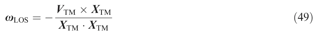
In practice,ωLOSis extracted from the data detected by the infrared seeker.1,28,29Substituting Eq.(45)into another expression related to aMyields
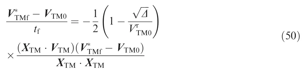
Using Eqs.(48)and(50),the OTG laws can be expressed in terms of the angular velocity of LOS,as follows:
(1)Optimal terminal guidance without constraint on VTMf
Substituting Eq.(48)into Eq.(31)yields

(2)Optimal terminal guidance with constraint on VTMf
Substituting Eqs.(48)and(50)into Eq.(36)yields

In practice,the guidance command is generated in real time by substituting the current states of motion into Eq.(51)or Eq.(52).
Note that Eqs.(51)and(52)are more suitable for practice than Eqs.(31)and(36);because(1)due to the help of the infrared seeker,the estimation accuracy of the angular velocity of LOS is much higher than that of the remaining flight time(i.e.time to go),especially when the missile is very close to the target;(2)since the time to go appears in the denominators of the guidance formulas,the miss distance is highly sensitive to the estimation error of the time-to-go,especially if there is a bias error in the estimated time-to-go.1,30In addition,because XTM0also appears in a denominator of Eq.(52),if there is a measurement error of the relative position,it can result in a waste of fuel and may even cause the missile to miss the target.Section 6.2 gives an example to show the influence of the measurement error.
In Ref.1,Zarchan demonstrated that the 2D PN expressed in terms of ZEM and tgois equivalent to that expressed in terms of the angular rate of LOS by geometrically analyzing the relationship between ZEM and the angular rate of LOS.Different from Ref.1,the trans formation method presented here is proposed for 3D guidance laws and based on vector operations,rather than geometric analysis.Additionally,the consideration of gravity greatly increases the difficulty of trans formation and causes the method presented in Ref.1to fail to handle the OTG cases.
6.Results and discussion
6.1.OTG without constraint on VTMf
In this subsection,some examples are given where VTMfis unconstrained.In these examples,the simulation results of OTG are compared with that of PN,APN,and PG.The commands of OTG,PN,and APN can be expressed uniformly as
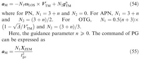
where N1=3+n and XZEMis the zero-effort miss vector.In each guidance cycle of PG,the onboard computer lets aM=0 and then integrates Eqs.(1)–(4)numerically.When X9m·VTM=0,the simulation stops.Then,let tgobe equal to the stop time and let XZEMbe equal to the value of XTMat the stop time.PG uses the component of aMperpendicular to the LOS as the guidance command.
Consider two cases about the PIP here:Case 1.the PIP has no error;Case 2.the PIP has an error of about 50 km.
In Case 1,the initial states of the KKV are XM0=[786280.91,-1300973.39,7286277.30]Tm and VM0=[2837.72,5409.49,1553.36]Tm/s,and the initial states of the target are XT0=[981407.04,-861312.60,7722585.39]Tm and VT0=[1725.21,-6831.13,-976.11]Tm/s.In this case,let n=0 for all thefour guidance laws.Define the velocity increment ΔV as
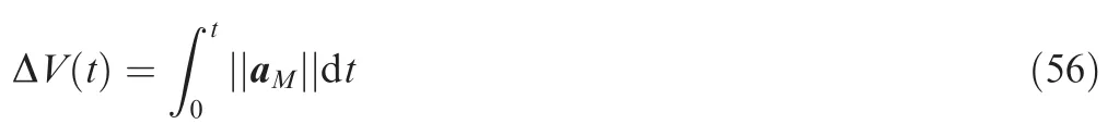
Because the thrust acceleration is proportional to the mass flow rate of fuel,ΔV reflects thefuel consumption.
The simulation results are shown in Table 1 and Figs.6–9.As can be seen from Table 1,PG consumes the least fuel,but requires the heaviest computational load.The velocity increment of OTG is almost as small as that of PG,but the computing time of OTG is much shorter than that of PG.Additionally,the velocity increment of APN is almost half that of PN.Fig.6 shows the trajectories and the correspondingground tracks of the missile and target for OTG.Because the trajectories for thefour guidance laws are nearly coincident and not easily distinguishable,only the trajectories for OTG are presented here.Fig.7 shows the histories of the velocity increments for all the guidance laws.Define plane PEMTas the plane containing the Earth center,missile,and target.Define^ynas the unit vector that is perpendicular to the current LOS in plane PEMTand has a positive projection on XM.Define^znas the unit vector perpendicular to plane PEMTand determined byFig.8(a)shows the histories of the components of aMalongy^n,denoted as.Fig.8(b)shows the histories of the components of aMalong^zn,denoted asFrom Fig.8,it can be seen that due to the use of inaccurate gravity models,PN and APN cause the missiles to per form unnecessary maneuvers and thus result in an apparent waste of fuel.Fig.9 shows the histories of gTMand XTMfor OTG.Here,it can be seen that both gTMand XTMvary almost linearly with time.Fig.9(b)indicates that the direction of LOS is almost unchanged during the interception.
Table 1 Comparisons of simulation results in Case 1.

Fig.6 Engagement trajectories for OTG in Case 1.

Fig.7 Histories of velocity increments in Case 1.
Fig.8 Histories of guidance commands in Case 1.

Fig.9 Histories of gTMand XTM for OTG in Case 1.

Table 2 Comparisons of simulation results in Case 2.
Now Case 2 is considered where there is a large PIP error of about 50 km in the beginning.To show the in fluence of the initial distance on the linearity of the gravity difference,the initial separation is enlarged to about 4000 km.The initial conditions are XM0=[192442.95,-2085138.26,6726394.99]Tm,VM0=[3418.94, 5190.08, 3269.23]Tm/s, XT0=[569875.90,1928987.06,7526018.77]Tm,and VT0=[2262.74,-6806.83,834.46]Tm/s.In this case,the parameter n of the four guidance laws is set to 1.The simulation results are shown in Table 2 and Figs.10–13.From Table 2,it can be seen that the velocity increments for OTG and PG are still significantly smaller than the other two,but the computing time for PG is much longer than the others.Also because the trajectories for the four guidance laws are very similar,Fig.10 only shows the trajectories and the corresponding ground tracks for OTG.Fig.11 shows the histories of the velocity increments.Fig.12 shows the histories of the acceleration commands for the four guidance laws.As can be seen from Fig.12(a),in PN,because the effect of gTMis not considered,the ZEM is underestimated and thus the commanded acceleration is insufficient in the beginning,which results in a large lateral divert requirement in the latter part of the trajectory.On the contrary,APN overestimates the ZEM since it assumes that gTMis constant throughout the remaining flight and equal to the current value.There fore,the maneuvering acceleration is too large in the beginning.This causes that the missile has to change the direction of thrust to the opposite in the latter part of the flight.By contrast,OTG estimates the ZEM accurately and thus control the missile to per form proper maneuvers.There fore,as shown in Fig.11,OTG requires much smaller velocity increment than PN and APN.From Fig.13,it can be seen that although the initial separation is up to 4000 km,gTMand XTMstill vary almost linearly with time.

Fig.10 Engagement trajectories for OTG in Case 2.

Fig.11 Histories of velocity increments in Case 2.
Define RTGPas the distance at which the terminal guidance phase starts.Now observe how RTGPinfluences the velocity increments of PN,APN,and OTG.In the simulations conducted here,there are two flight phases.The first phase is the coast phase where the missile is only governed by gravity and thus flies along a ballistic trajectory.When the distance between the missile and target reduces to RTGP,the terminal guidance phase begins.Here,two cases about the coast phase are considered:(1)the missile is just on a collision course,which means that there is no PIP error,and(2)the trajectory of the missile has a PIP error of about 5 km.By setting RTGPto different values and then conducting a large number of simulations,the profiles of the velocity increments with respect to RTGPcan be obtained,as shown in Fig.14.Here,Fig.14(a)shows the profiles corresponding to the case without PIP error,and Fig.14(b)shows the profiles corresponding to the case with PIP error.As shown in Fig.14(a),it can be seen that OTG has very high fuel efficiency,compared with PN and APN.This figure also shows that the amount of the wastefuel for APN is about half that for PN.As shown in Fig.14(b),shorter RTGPtends to increase the required heading correction and thus increase the lateral divert requirement.Inversely, for OTG,longer RTGPtends to reduce the lateral divert requirement significantly.However,because PN and APN adopt the inaccurate gravity models and thus cause the missile to per form unnecessary maneuvers,longer RTGPtends to increase the lateral divert requirements for PN and APN.
Fig.12 Histories of the guidance commands in Case 2.

Fig.13 Histories of gTMand XTM for OTG in Case 2.
Fig.14 Prof iles of ΔV versus RTGP.
6.2.OTG with constraint on VTMf
Now consider the cases with constraint on VTMf,where it is desired that the missile collides head-on with the target.As a comparison,the results of generalized vector explicit guidance(GENEX)17are also given here.Although GENEX is originally expressed in terms of ZEM and tgo,using the trans formation method shown in Section 5,GENEX can also be re formulated in terms of the angular velocity of LOS as follows:
The parameter n appearing in Eqs.(52)and(57)is set to be 1.Be fore launching the missile,the command and control center can figure out the position of the PIP and the velocity vector of the target at the PIP,where the unit vector of the velocity vector of the target at the PIP is denoted as^vTf.Then, for a head-on collision,let the desired final relative velocity vector be

A scenario is considered here that although the intercept trajectory has been planned perfectly with^vTf=[-0.1840,-0.9720,-0.1462]T,due to the guidance error at the boost phase,the missile has a heading error of about 0.5°at the beginning of the terminal guidance phase.For this scenario,at the terminal guidance phase,the initial conditions are XM0=[354390.76,-1468209.45,6924581.65]Tm,VM0=[1142.97, 4964.53, 2714.43]Tm/s, XT0=[942888.61,1633401.66, 7406664.03]Tm, and VT0=[-1168.38,-6981.35,680.63]Tm/s.
To show the influence of the measurement error of XTMon OTG,an additional case is considered where it is assumed that the measured magnitude of XTMis 100 m less than its real value and OTG is used as control.
The simulation results are shown in Table 3 and Figs.15–17,where the solid lines represent the ideal results of OTG,the dashed lines represent the ideal results of GENEX,and the dotted lines represent the results of the case with the measurement error of XTM.As can be seen from Table 3,the velocity increment of OTG is about half that of GENEX,and the measurement error of XTMleads to morefuel consumption.Also because the trajectories for the three cases are very similar,Fig.15 only shows the trajectories and the corresponding ground tracks for OTG.Define θ as the angle between thevelocity vectors of the missile and target.Fig.16 shows the histories of ΔV and θ.From Fig.16(a),it can also be seen that the velocity increment of OTG is much smaller than that of GENEX.From Fig.16(b),it can be seen that θ goes to 180°finally,which means that the missile hits the target from the head-on direction.As can be seen from Fig.17(a),because GENEX does not consider the effect of gravity,GENEX causes the missile to per form some unnecessary maneuvers and thus results in a waste of fuel.In Fig.17(b),because gTMhas no component along^zn,OTG and GENEX are almost the same in this direction and thus generate the similar acceleration commands.In the case with measurement error of XTM,when the missile is close enough to the target where the distance between them is within hundreds of meters,the measurement error results in rapid changes in the guidance command,which leads to fuel waste and a large error in θ.

Table 3 Comparisons of simulation results with constraint on VTMf.

Fig.15 Engagement trajectories for OTG with constraint on VTMf.
6.3.Improved pulsed guidance
An example is given here to show that some achievements of this paper can be used to improve thefuel efficiency of the pulsed guidance law employed by the missile with fixed thrust level.

Fig.16 Histories of ΔV and θ for the cases with constraint on VTMf.
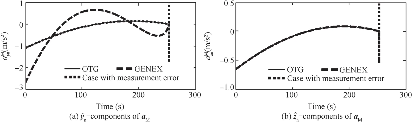
Fig.17 Histories of guidance commands for the cases with constraint on VTMf.
Zarchan introduced a 2D pulsed guidance law and demonstrated its performance in the long-range exoatmospheric interception.1Here,the guidance is extended to a 3D one and called the basic pulsed guidance(BPG)law.In general,KKV has four divert thrusters in a cruciform con figuration.Assume that the axis of a pair of coaxial thrusters remains along^yn,while the axis of the other pair of coaxial thrusters remains along^zn.The components of XZEMalong^ynand^znare denoted asrespectively.
As shown in Fig.18,if there is a guidance pulse of magnitude aMlasting for Δt seconds,then the pro file of the lateral maneuvering speed ΔV consists of two segments.In such a case,the lateral maneuvering range is equal to the area of the region enclosed by the time axis and lines depicted in Fig.18(b).
As the guidance tries to remove the predicted ZEM using one pulse,let the displacement due to thrust be equal to the predicted XZEMas
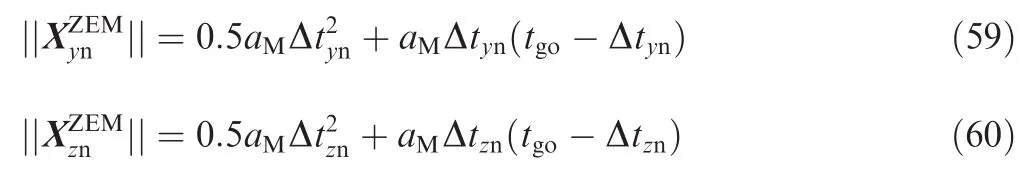

Fig.18 Sketch map of pulsed guidance.


Table 4 Comparisons of simulation results for BPG and IPG.

Fig.19 Engagement trajectories for IPG.

Fig.20 Histories of ΔV and predicted ZEM for IPG and BPG.
Here,Δtynis the commanded duration time for the thrust with the same direction asand Δtznthe commanded duration time for the thrust with the same direction asSolving the above two equations,we obtain Note again that<0.Because the above prediction formulas are inaccurate due to the ignorance of gravity,one trajectory correction cannot eliminate all the real ZEM.There fore,more trajectory corrections are needed.In Ref.1,these corrections are distributed at equal intervals during the flight.To reduce the miss distance,this scheme is slightly modified as:when tgo>30 s,the trajectory correction is conducted every 30 s,but when tgo≤30 s,the trajectory correction is conducted every 5 s.
Using some achievements of this paper,the prediction formulas of XZEMand tgoconsidering the effect of gravity can be obtained.From Ref.1,there iswhere N1=3+n.By comparing this with Eq.(31),we obtain

The initial conditions for the current case are the same as those for Case 2 in Section 6.1.The simulation results are shown in Table 4 and Figs.19–21.As can be seen from Table 4 and Fig.20(a),because IPG gives full consideration to the effect of gravity,its miss distance and velocity increment are much smaller than those of BPG.In Fig.19,only the trajectories and the corresponding ground tracks for IPG are presented,also because the trajectories for IPG and BPG are very similar.As shown in Fig.20(b),because IPG predicts the ZEM accurately and controls the missile to per form lateral maneuvers properly,the predicted ZEM of IPG remains nearly zero after the first trajectory correction.Fig.21 shows the histories of the lateral maneuvering accelerations.
7.Conclusions
In this paper,using optimal control theory,two optimal terminal guidance laws are developed for exoatmospheric interception:one considers thefinal velocity vector constraint,whereas the other does not consider it.Because the developed guidance laws givefull consideration to the effect of gravity and need not conduct any onboard trajectory simulation,the new guidance laws consume much less fuel than the traditional guidance laws while demanding a light computational load.To convert the OTG laws expressed in terms of XTM,VTMand tgointo that expressed in terms of ωLOS,the 3D trans formation method based on vector operations is proposed,which considers the effect of the gravity difference,especially on theflight time.Additionally,an example is given to show that if the prediction formulas of XZEMand tgoproposed in this study are applied to the pulsed guidance law,the fuel efficiency of the guidance law can be significantly improved.Different from PN,the implement of the OTG laws requires the in formation on the positions of the missile and target in order to calculate the gravity difference and guidance coefficients.
1.Zarchan P.Tactical and strategic missile guidance.6th ed.Virginia:AIAA Progress in Aeronautics and Astronautics;2012.p.299–323.
2.Yuan CL.Homing and navigation courses of automatic targetseeking devices.J Appl Phys 1948;19(12):1122–8.
3.Adler FP.Missile guidance by three-dimensional proportional navigation.J Appl Phys 1956;27(5):500–7.
4.Bryson AE,Ho YC.Applied optimal control.Waltham:Blaisdell;1969.p.148–76.
5.Guelman M.The closed- form solution of true proportional navigation.IEEE Trans Aerosp Electron Syst 1976;12(5):472–82.
6.Becker K.Closed- form solution of pure proportional navigation.IEEE Trans Aerosp Electron Syst 1990;26(3):526–33.
7.Yu WB,Chen WC.Guidance law with circular no fly zone constraint.Nonlinear Dyn 2014;78(3):1953–71.
8.Yang CD,Yang CC.Analytical solution of generalized 3D proportional navigation.In:Proceedings of the 34th conference on decisionamp;control;1995 December 13-15;New Orleans,LA,USA.Piscataway.NJ:IEEE Press;1995.p.3974–9.
9.Yang CD.Analytical solution of 3D true proportional navigation.IEEE Trans Aerosp Electron Syst 1996;32(4):1510–22.
10.Li K,Zhang T,Chen L.Ideal proportional navigation for exoatmospheric interception.Chin J Aeronaut 2013;26(4):976–85.
11.Su WS,Yao DN,Li KB,Chen L.A novel biased proportional navigation guidance law for close approach phase.Chin J Aeronaut 2016;29(1):228–37.
12.Garber V.Optimum intercept laws for accelerating targets.AIAA J 1968;6(11):2196–8.
13.Cottrell RG.Optimal intercept guidance for short-range tactical missiles.AIAA J 1971;9(7):1414–5.
14.Turetsky V,Shinar J.Missile guidance laws based on pursuitevasion game formulations.Automatica 2003;39(4):607–18.
15.Ge L,Shen Y,Gao Y,Zhao L.Head pursuit variable structure guidance law for three-dimensional space interception.Chin J Aeronaut 2008;21(3):247–51.
16.Cherry GW.A general,explicit optimal guidance law for rocketpropelled spacecraft.In:The AIAA/ION astrodynamics guidance and control conference;1964 Aug 24-26;Los Angeles,California,USA.Reston:AIAA;1964.p.1–2.
17.Ohlmeyer EJ,Phillips CA.Generalized vector explicit guidance.J Guidance Control Dyn 2006;29(2):261–8.
18.Yu WB,Chen WC.Trajectory shaping guidance with final speed and load factor constraints.ISA Trans 2015;56:42–52.
19.Wang H,Lin De,Cheng Z.Optimal guidance of extended trajectory shaping.Chin J Aeronaut 2014;27(5):1259–72.
20.Ben-Asher JZ,Yaesh I.Advances in missile guidance theory.Virginia:AIAA Progress in Aeronautics and Astronautics;1998.p.25–88.
21.Kim M,Grider KV.Terminal guidance for impact attitude angle constrained flight trajectories.IEEE Trans Aerosp Electron Syst 1973;9(6):852–9.
22.Ryoo CK,Cho H,Tahk MJ.Time-to-go weighted optimal guidance with impact angle constraints.IEEE Trans Control Syst Technol 2006;14(3):483–92.
23.Zhao J,Zhou R.Three-dimensional cooperative guidance laws against stationary and maneuvering targets.Chin J Aeronaut 2015;28(4):1104–20.
24.Yang L,Zhou H,Chen WC.Application of linear gauss pseudospectral method in model predictive control.Acta Astronaut 2014;96(1):175–87.
25.Hablani HB.Endgame guidance and relative navigation of strategic interceptors with delays.J Guidance Control Dyn 2006;29(1):82–94.
26.Ratnoo A,Ghose D.Collision-geometry-based pulsed guidance law for exoatmospheric interception.J Guidance Control Dyn 2009;32(2):669–74.
27.Newman B.Strategic Intercept midcourse guidance using modified zero effort miss steering.J Guidance Control Dyn 1996;19(1):107–12.
28.Lyzhof t J,Wie B.IR telescope and sensor characterization for hypervelocity asteroid intercept guidance.In:AAS/AIAA spaceflight mechanics meeting;2014 Jan 26-30;Santa Fe,New Mexico,USA.Reston:AIAA;2014.p.1–17.
29.Waldmann J.Line-of -sight rate estimation and linearizing control of an imaging seeker in a tactical missile guided by proportional navigation.IEEE Trans Control Syst Technol 2002;10(4):556–67.
30.Ben-Asher JZ,Yaesh I.Optimal guidance with reduced sensitivity to time-to-go estimation errors.J Guidance Control Dyn 1997;20(1):158–63.
Yu Wenbin received the B.S.degree in aerospace engineering from Beihang University in 2010.After that,he was recommended for pursuing the doctor’s degree directly also in Beihang University and received it in 2016.Now he is a postdoctoral researcher in Beihang University.His main research interests are flight mechanics,guidance and control.
Chen Wanchun received the B.S.,M.S.and Ph.D.degrees in aerospace engineering,Beihang University,Beijing,in 1986,1989,and 1995,respectively.Since 1989,he has been with the School of Astronautics,Beihang University,where he is currently a Prof essor and Ph.D.supervisor.His main research interests include flight Mechanics,guidance and control,and trajectory optimization.
Yang Liang received the Ph.D.degree in Beihang University.His research interests areflight mechanics,guidance and control,and trajectory optimization.
Liu Xiaoming is a Ph.D.and lecturer in Beihang University.His research interests areflight Mechanics,guidance and control,in formation fusion,and sensors applications.
Zhou Hao received his Ph.D degree in Beihang University and then became a lecturer there.His research interests areflight mechanics and trajectory optimization.
1 October 2015;revised 7 December 2015;accepted 7 March 2016
Available online 23 June 2016
Exoatmospheric interception;
Explicit guidance;
Guidance;
Optimal control;
Proportional navigation;
Pulsed guidance
©2016 Chinese Society of Aeronautics and Astronautics.Production and hosting by Elsevier Ltd.Thisisan open access article under the CC BY-NC-ND license(http://creativecommons.org/licenses/by-nc-nd/4.0/).
*Corresponding author.Tel.:+86 10 82339226.
E-mail address:yangliang.buaa@hotmail.com(L.Yang).
Peer review under responsibility of Editorial Committee of CJA.
Production and hosting by Elsevier
http://dx.doi.org/10.1016/j.cja.2016.04.019
1000-9361©2016 Chinese Society of Aeronautics and Astronautics.Production and hosting by Elsevier Ltd.
This is an open access article under the CC BY-NC-ND license(http://creativecommons.org/licenses/by-nc-nd/4.0/).
杂志排行
CHINESE JOURNAL OF AERONAUTICS的其它文章
- Numerical simulation of aerodynamic interaction for a tilt rotor aircraft in helicopter mode
- Investigation of MHD power generation with supersonic non-equilibrium RF discharge
- Experimental study on ceramic membrane technology for onboard oxygen generation
- Transition study of 3D aerodynamic configures using improved transport equations modeling
- Numerical investigation of aerodynamic flow actuation produced by surface plasma actuator on 2D oscillating airfoil
- Characterization of component interactions in two-stage axial turbine