Numerical simulation of aerodynamic interaction for a tilt rotor aircraft in helicopter mode
2016-11-24YeLiangZhangYingYangShuoZhuXinglinDongJun
Ye Liang,Zhang Ying,Yang Shuo,Zhu Xinglin,Dong Jun
Aviation Key Laboratory of Science and Technology on Aerodynamics of High Speed and High Reynolds Number,AVIC Aerodynamics Research Institute,Shenyang 110034,China
Numerical simulation of aerodynamic interaction for a tilt rotor aircraft in helicopter mode
Ye Liang*,Zhang Ying,Yang Shuo,Zhu Xinglin,Dong Jun
Aviation Key Laboratory of Science and Technology on Aerodynamics of High Speed and High Reynolds Number,AVIC Aerodynamics Research Institute,Shenyang 110034,China
A rotor CFD solver is developed for simulating the aerodynamic interaction phenomenon among rotor,wing and fuselage of a tilt rotor aircraft in its helicopter mode.The unsteady Navier–Stokes equations are discretized in inertial frame and embedded grid system is adopted for describing the relative motion among blades and nacelle/wing/fuselage.A combination of multi-layer embedded grid and ‘extended holefringe” technique is complemented in original grid system to tackle grid assembly difficulties arising from the narrow space among different aerodynamic components,and to improve the interpolation precision by decreasing the cell volume discrepancy among different grid blocks.An overall donor cell searching and automatic hole cutting technique is used for grid assembly,and the solution processes are speeded up by introduction of OpenMP parallel method.Based on this solver,flow fields and aerodynamics of a tilt rotor aircraft in hover are simulated with several rotor collective angles,and the corresponding states of an isolated rotor and rotor/wing/fuselage model are also computed to obtain reference solution.Aerodynamic interference influences among the rotor and wing/fuselage/nacelle are analyzed,and some meaningful conclusions are drawn.
1.Introduction
Tilt rotor aircraft is a promising flight vehicle with the adaptability to operate in landing and taking of f vertically like a helicopter as well as convert to propeller mode to achieve relatively high speed forward flight.Compared with conventional helicopter and fixed-wing turboprop aircraft,theflow fields and aerodynamic environments around the tilt rotor are more complicated,which partly due to the unique structure and movement features of the vehicle.
When a tilt rotor aircraft works in helicopter mode,the aerodynamic interactions among the rotor and wing/fuselage are of major concern.The rotor is only about one wing chord above the wing,so theflow induced by the wing and rotor is closely coupled.Impingement of the rotor downwash on the wing causes a download on the wing,which reduces the payload carrying capability.The impact of rotor downwash on the wing aerodynamics was studied by Smith et al.1with Euler equations and Kjellgren et al.2with large eddy simulation(LES)model.The air load of a quad tilt rotor was computed by Lee-Rausch and Biedron3and Gupta and Baeder4using Fun3D and Overflow solver respectively and that was also calculated by Sitataman and Baeder5using thefree wake/Navier–Stokes hybrid method.The governing equations in rotational frame were resolved by Potsdam and Strawn6in order to give theflow fields and aerodynamics of a tilt rotor with a fixed rotor blade azimuth.In recent years,tilt rotor flow fields research based on CFD method has also been conducted in China,and progress has been made(see Refs.7–9).
When previous research works are reviewed,wefind that the contents and numerical methods used commonly are restricted by the technique itself and computer resource limitation at that time.The viscosity influence cannot be considered when the Euler equations are used.1Parts of components are used for simulation.For example,2only the wing section is considered,but actual action of the rotor is not modeled.The actuator model,4,5,8with which impaction of rotor downwash on the wing can be modeled,or the method by discretizing governing equations in rotation frame,6simplifies theflow to a quasi-steady one,and unsteady effects,important in general,are ignored during simulations.The unsteady simulation,with the rotor blade modeled with its actual configuration,is a more accurate method for tilt rotor aerodynamic interaction.Interference among rotors and wing in different blade azimuthal positions were discussed only with certain rotor collective angle in literature6,7,and some aerodynamic components were not counted.For example,only wing and rotor were simulated excluding the influence of fuselage and nacelle.7
The viscosity,unsteady flow,and the interaction among components(wing,fuselage,and nacelle)may exert a critical impact on the overall performance estimation.The numerical methods,which take most parts of the tilt rotor aircraft aerodynamic components into account and treat theflow as unsteady,are meaningful for theflow mechanism comprehension and future aircraft design work.The research can also be improved by more detailed CFD simulation with multi-status input considered.
The embedded grid system is generally used in rotor aircraft flow fields due to the existence of large amplitude relative motion among different aerodynamic components.Previous developed domain connectivity methods,which include donor cell searching and hole cutting methods,have been widely studied.Various methods are developed,such as implicit hole cutting methods,10object ray method,11top view map,12neighbor-to-neighbor(N2N)13and alternating digital tree(ADT)method.14,15However,new difficulties arise when most parts of important aerodynamic components of a tilt rotor aircraft are taken into account,including rotor,wing,nacelle,fuselage,and the flow fields around it need to be simulated time-accurately.One aspect of difficulties is from the embedded grid assembly and data transfer.Domain connectivity might fail when the grid partitions of overlap region among different blocks are not sufficient.The other is from computational resource consumption and efficiency decrease.In order to describe theflow details around these components and maintain the interpolation precision,numerous grid cell numbers are needed,which overburden the computational task.For an embedded grid system generated to describe a tilt rotor aircraft,the cells used for data transfer(donor or recipient)among different grid blocks usually have large cell volume discrepancy,especially for those cells belonging to different grid blocks which describe components with different spatial scale.Numerical precision descends rapidly when the data exchanges among these grid block cells.At the same time,the outer boundary range of minor grids is limited by the narrow space between the rotors and wing/fuselage,and there may be only few background cells in the space region where the minor grid blocks traverse,which makes the grid assembly fail.Grid refinement in large space region is resource consuming,and the background grid refinement be forehand is almost impossible for more complicated rotor movement states due to the reason that the position for background grid refinement cannot be predicted.
Mainly focusing on the tilt rotor working in its helicopter mode,a tilt rotor aircraft model,which is composed of rotor,nacelle,wing and fuselage configurations,is used for numerical simulation.Flow fields and aerodynamics of isolated rotor and the vehicle with different component combination are computed and compared with each other in several rotor blade collective angles.Unsteady Navier–Stokes equationsin conservation-law form are solved in inertial frame.The temporal discretization algorithm is an implicit dual-time stepping method with lower–upper symmetric Gauss–Seidel(LU-SGS)sub-iteration and 2nd-order accuracy in spatial discretization is obtained by reconstruction.Parallel computing technique is used to cut the time consumption and improve the efficiency.A multi-level embedded grid and ‘extended holefringe” technique is put forward in this paper to alleviate volume discrepancy among the cells for data transfer and to decrease the requirement of background refinement.The previously developed automatic hole cutting technique which is based on overall N2N donor searching,is also used in grid assembly process in those regions where the extended hole is not used.The domain connectivity duty is resolved and the interpolation precision is ameliorated when the data-exchanges happen among cells with approximate scale and belonging to different grid blocks.
Numerical results show that intense unsteady aerodynamic characteristics exist for tilt rotor aircraft in helicopter mode.The interaction among the wing/fuselage and the rotor,which changes the aerodynamic environment of the total aircraft,brings out unsteady aerodynamic load variation for the vehicle.The variation process of the rotor blade thrust contains the decreasing and recovering parts in one revolution.The thrust of the blade tip sections dramatically drops when the blade traverses through thefountain flow region,and it cannot be counteracted by the benefit gained from the ‘ground effect’,which makes the rotor overall performance hard to evaluate.The aerodynamics differences occur when different combinations of aerodynamic components are considered.The interaction among the components is discussed at different working status.Details of flow fields,including vorticity evolution,fountain flow phenomenon and separated flow beneath the wing/fuselage,can be described,which indicates that the present numerical methods based on multi-level embedded grids and extended holefringe can work well when coupled with overall donor searching/automatic hole cutting method,and are effective for flow fields simulation of tilt rotor in helicopter mode.
2.Methodology
2.1.Grid system
When several aerodynamic components of a tilt rotor aircraft are simulated,the ratios of cell volume among different grid blocks are usually large,especially for those grid blocks which describe components with different spatial scale.Loss of precision occurs when the data is exchanged among cells which respectively belong to blade body-fitted grid blocks and background grid blocks due to the worse cell volume matching.
On the other hand,the outer-boundary range of minor grid(blade body-fitted grid)blocks cannot be too large as it is limited by the narrow space among the rotors and wing/fuselage beneath it.Data exchange region construction difficulty arises when a relatively sparse background grid is used,as there might be only few background cells in the space region where the minor grid blocks traverse through.This phenomenon happens morefrequently when the rotor works with an axial tilt angle,and the refinement of background grid cannot be forecasted.The quantity requirement of background cells increases rapidly for grid assembly,which overburdens the simulation tasks.
For these reasons,a multi-level embedded grid system and‘extended holefringe” method are proposed in this paper to alleviate the background grid refinements which are almost compulsory for successful grid assembly formerly and to lessen the volume scale ratio discrepancy among data-exchange cells.The previously developed automatic hole cutting technique which is based on overall N2N donor searching is also used in grid assembly process in those regions where the extended hole is not used.
2.1.1.Multi-level embedded grid
The grid system is composed of three parts which can be described as follows:
(1)Minor grid blocks(blade body-fitted grid blocks),which describe the configuration of blades and move with the blades(rotation,pith,etc.).
(2)Mediator grid blocks(nacelle body-fitted grid blocks),which surround all minor grid blocks,describe the nacelle configuration,and transfer data among the minor grid blocks and background block as a mediator.
(3)Background grid,which contains all the other grid blocks and describes the wing/fuselage configuration.
2.1.2.Donor cell identification and automated ‘hole cutting’’The method used for domain connectivity is described briefly as follows,and the details can be retrieved in Ref.16.
(1)Layer number construction: for each grid block,cells are marked with layer number according to its adjacency to the body surface.
(2)Donor and hole cell identification:For each cell in every grid block,the donor cells are searched in all the other grid blocks with N2N method,and hole cutting results are obtained as a byproduct of the donor searching.The process is automatic and the hole range is adjustable by setting the control parameters(layer numbers of donor cells).
(3)Interpolated boundary identification:we loop over all the grid cells,and the cell which is adjacent to ‘hole cell”is defined as ‘interpolated cell”.
The efficiency of algorithm is critical since donor searching is per formed many times in flow simulation process.To achieve the maximum efficiency,the donor identification results obtained in last physical time are used as an initial guess for the next step searching.
2.1.3.‘Extended holefringe’and data transfer
With the multi-level grid system, ‘extended holefringe”concept can be brought forward,and the hole in background grid which is cut by the blade configuration can be extended to the range outside the minor grid outer boundary.The domain connectivity conditions are still satisfied only with the assumption that the extended holefringe does not exceed the nacelle grid outer boundary,and the data exchange process can be carried out properly.Fig.1 is the schematic of computational domain of a 2D aerof oil multi-layer embedded grid after extended hole cutting.
There is no straight forward data exchange among the background and minor grid blocks when the nacelle grid block is used as the mediator.The interpolation process is only carried out between the nacelle block and the minor grid blocks or the background grid block,and volume ratio among the cells which are used for data exchange is decreased,especially in the high gradient region where the aerodynamic components are close to each other,which improves the accuracy for flow field simulation.
An overall view of the embedded grid for tilt rotor aircraft con figuration(3 grid systems:background,nacelle,and blades)is shown in Fig.2,and a close-up view of the grid assembly and hole cutting is shown in Fig.3.
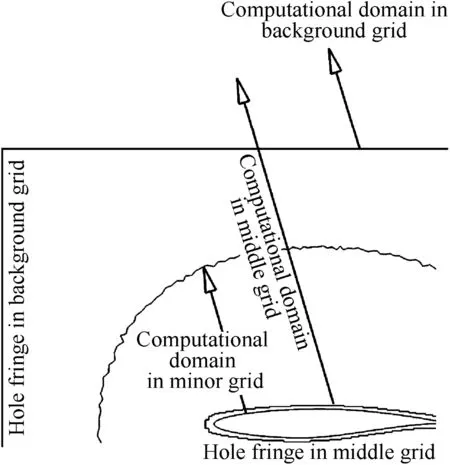
Fig.1 Schematic of computational domain of a 2D aerof oil multi-layer embedded grid with extended holefringe.
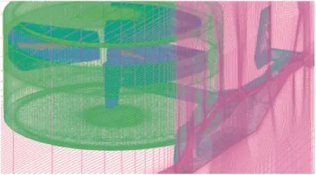
Fig.2 Schematic of embedded grid system for tilt rotor aircraft configuration.
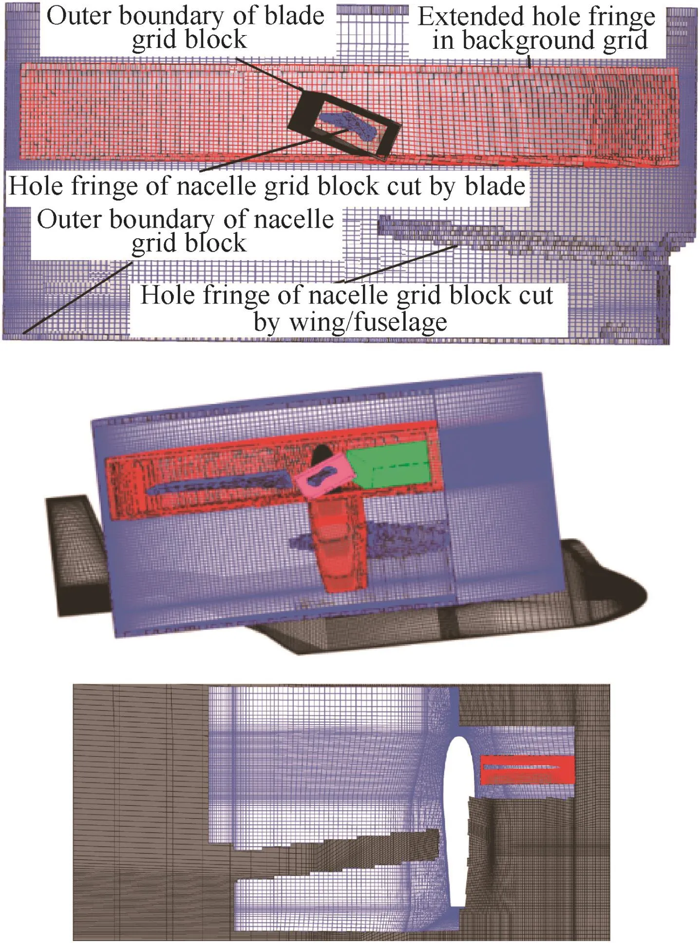
Fig.3 Close-up view of grid assembly and hole cutting.
2.2.Numerical method
2.2.1.Governing equations
The Navier–Stokes equations,written in time-dependent integral form for a moving control volume Ω with a surface element dS,are as follows:
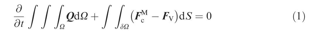
The vector of the conservative variables Q=[ρ, ρu, ρv, ρw, ρE]T,the vector of the convectivefluxeswhere ρ denotes the density, (u,v,w)theflow velocity,(nx,ny,nz)the unit normal vector,E the total energy,H the total enthalpy per unit mass and p the pressure.Vtis the contravariant velocity of theface of the control volume,Vrrepresents the contravariant velocity relative to the motion of the grid,and Vr=V-Vt.Fvis the vector of the viscous fluxes.
For a cell-centered scheme,theflow variables are stored at the center of the grid cells.Only hexahedron elements are used for grids quality consideration,although there is no topology restriction as the discretization methodologies applied to the convective and viscous fluxes of the governing equations are designed for unstructured/mixed grids in essential.
2.2.2.Discretization of convectivefluxes
Theflux-difference splitting scheme of Roe17is a widely employed approach in convectivefluxes computation:
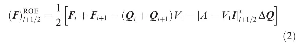
where F is the convectivefluxes,|·|*the Jacobian matrix of Roe’s scheme;subscript i,i+1 and i+1/2 represent left,right cell and the interface respectively.I is identity matrix.
Second-order accuracy of numerical scheme can be derived by using some interpolation algorithm(solution reconstruction),which provides a mapping from the conservative variables stored at cell center to fluxes at the cell faces.Gradient of dependent variables stored in the cell center can be calculated with the Gauss–Green law.The limiter functions presented by Venkatakrishnan18are adopted to prevent the generation of oscillations and spurious solutions in regions of high gradients for its superior convergence properties.
2.2.3.Turbulence model and wall distance computation
The viscous terms are calculated using a second-order central difference discretization.The Spalart–Allmaras(S–A)oneequation turbulence model19is used for eddy viscosity evaluation:
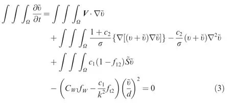
where υ is the laminar kinematic viscosity,~υ denotes the modified eddy viscosity,V is the velocity,c1,c2,CW1,κ,σ are constants,d the distance to the closest wall,~S is the modified magnitude of the rotation rate.fWand ft2stand for procedure variable.
The wall distance computation must be carried out in every physical time step as the relative location changes among aerodynamic components.Recursive box method20with less adaption is used in application for its high efficiency in multi-block grid system.
2.2.4.Boundary conditions
Three kinds of boundary conditions are used in our work.Nosilp boundary conditions are adopted at solid wall surfaces and the contravariant velocity relative to the motion of the grid is zero;non-reflecting boundary conditions are applied at the outer boundary of the computational domain,and symmetric boundary conditions are used at symmetric surfaces as only one-half of the tilt rotor aircraft model is simulated.
2.2.5.Dual time-stepping
A dual time-stepping approach is introduced for unsteady flows.Define that n is the physical time level and m is the pseudo-time level,and the equations can be replaced by
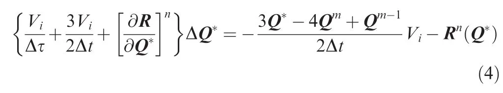
where Viis the volume of control unit Δt Δτ are physical time and pseudo time step Rn,and is the residual after the nth iteration in physical time domain,m,m-1 is sub-iteration in pseudo time.Thesolution ismarched forward in pseudo-time domain to the steady state through a matrixfree LU-SGS iteration algorithm.21The Courant–Friedrichs–Lewy(CFL)numbers that we used in our computations are up to 20,although there is no limitation for an implicit subiteration,and physical time step is equal to 1/360 rotating period.
2.2.6.Parallel computing
Parallelization is the process of restructuring of the sequential codes to run on multiprocessor systems by distributing the workload among the threads.OpenMP22is a set of compiler directives along with library routines to make an application program interface for supporting share-memory parallel programming.The code modification effort is relatively small for an OpenMP Parallelization,as all data is stored in a common memory and all threads have access to this place to store and retrieve variables and the grid partitions are not needed.
For multiprocessing to work properly,the variables in one loop must stand alone and the results must be unrelated to the order of execution.Three kinds of grid reordering are proposed.Thefirst one we proposed here is used for LU-SGS timestepping.After this reordering,every cell from one group has no connections with other cells from the same group.Ref.23was adapted(the vertex was substituted by the cell as the solver we used is cell-centered and Sharov’s is cell-vertex) for vectorization of the code and balance of the lower and upper matrices.The second one is that every vertex from one group has no connections with other vertex from the same group,as primitive variables of theflow fields will be interpolated to the vertex for gradient reconstruction.The last one is that every facefrom one group cannot share any left/right neighbor cell with the others,as the conservative variables must be updated in every sub-iteration at the same time,which will lead to memory dispute if this condition is not satisfied.The reordering is per formed only once be fore iterations are started.
Most sections of the code are parallelized except the input and output module with the nature of data dependency.Grid assembly module is executed with master thread only,as the grids are not partitioned physically.Speeding up achieves 4.8 for 8 threads with approximate 18 million hexahedron grid cells for computing,and the performance results may attribute to the structure of the code where many small subroutines are called for the ‘folk-join” processes24in OpenMP Parallelization.
3.Results and discussion
3.1.Flow fields and aerodynamics calculation on ‘GT rotor”geometry
The ‘GT rotor” geometry,which has been widely used for rotor-fuselage interaction calculation research by several researchers,is adopted as validation case.It has a 2-bladed rotor and a cylinder fuselage.The blades have no geometric twist and taper with rectangular plane form and NACA0015 airfoil sections.The advanced ratio is 0.1.Flap angle variation is taken from Ref.25.Fig.4 shows flow fields and aerodynamics for this geometry.The agreements among calculation and experimental data are good no matter for the time average or time accurate(blade azimuth ψ =0°,174°)pressure coefficient Cpalong thefuselage crown line.
3.2.Tilt rotor aircraft in helicopter mode
A simplified tilt rotor configuration which is similar to V-22 is used for numerical simulation.Due to the assumed symmetry of theflow field in hover,only one-half of the configuration is considered.Thefuselage length is 17.6 m and the wing semispan is 6.2 m.The rotor has 3 blades with 5.8 m radius;the blades consist of 3 different airfoil sections and have a nonconstant geometric twist(about-30°from root to tip).Symmetry boundary condition is used for cutting down the total grid cells requirements.Each of the rotor blade body-fitted grid blocks used in embedded grid system presented here contains almost 0.8 million cells;the background grid consists of approximately 12 million cells;nacelle grid block 3.5 million,resulting in a total of approximately 18 million grid cells for the overall analysis of the half tilt rotor aircraft.
Fig.5 is the schematic of coordinate system used in this paper,in which Z axis is along the longitudinal direction of fuselage and positive downstream,Y axis is parallel to the rotor rotational axis and positive up,and X axis is along wing spanwise direction and positive out the right side.The rotational direction is counterclockwise top view and zero azimuth of blade is downstream,as shown in this figure.The operating conditions are as follows:blade tip Mach number Matipis 0.7 and collective angles Φ7are 7.5°,10.0°,12.5°,15.0°and 17.5°.Flow fields of the isolated rotor and rotor/wing/fuselage model(without nacelle)in the same operating conditions are also computed for obtaining reference solutions.
In Fig.6,the sectional lift of isolated rotor is plotted over blade span(r/R is the proportional position of the span direction),which shows that the lift becomes larger and the lift coefficient CLpeak of blade sections moves towards the inboard direction and far from the blade tip with the rotor collective angle increasing.
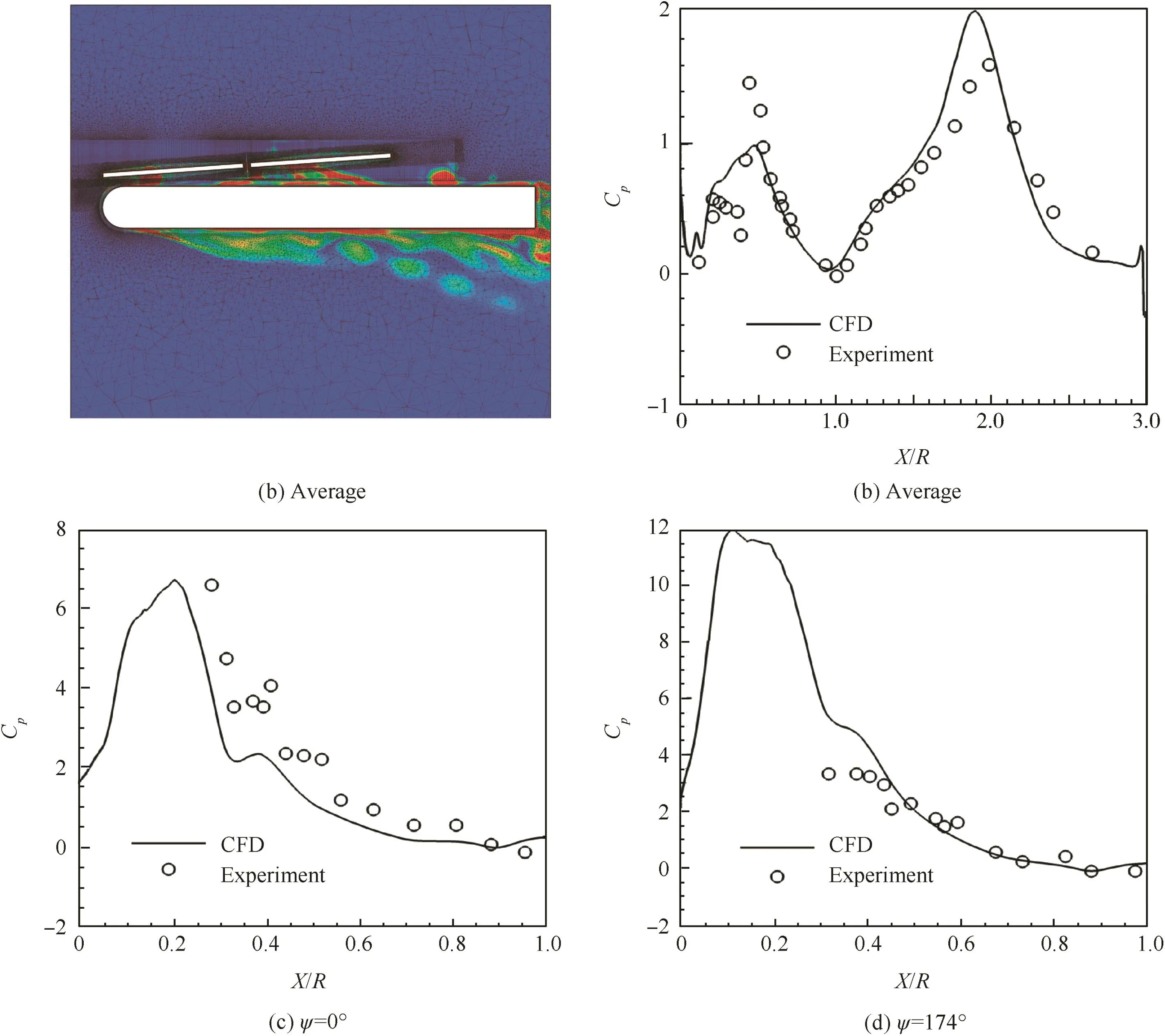
Fig.4 Flow field and aerodynamics for ‘GT rotor” geometry.
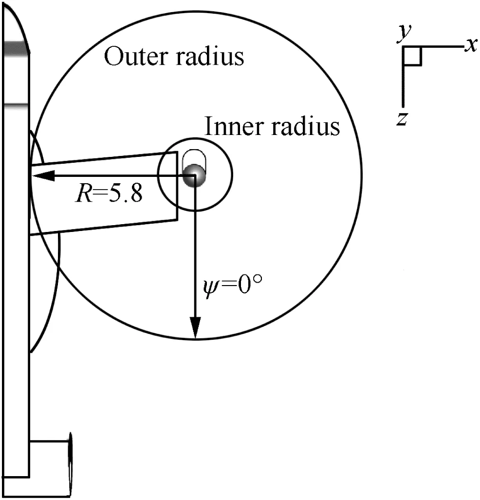
Fig.5 Schematic of coordinate system.
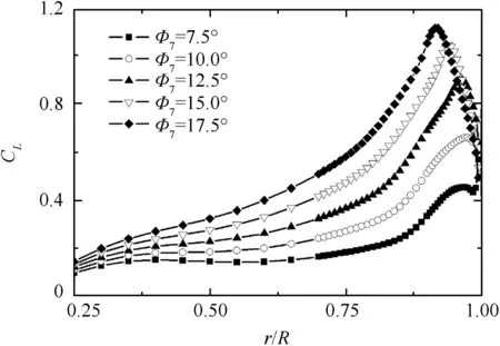
Fig.6 Blade spanwise lift coefficient of isolated rotor.
Fig.7 is the streamline and vorticity contour distribution on a vertical plane through rotor rotation center at different rotor collective angles for isolated rotor,rotor/wing/fuselage and rotor/wing/fuselage/nacelle combination model.It can be seen from thesefigures that a recirculating flow pattern called ‘fountain flow” is visible above the wing adjacent to the plane of symmetry when the rotor/wing/fuselage and rotor/wing/fuselage/nacelle are modeled,and the tip vortex development is clearly captured for all combinations.More complicated flow phenomenon is observed where downwash of the rotor is impinged with the wing;when the nacelle is taken into account,the wing spanwise(outboard direction)flow is blocked by nacelle,and a new strengthened vortex is generated at the cylinder region with the radius approximate to the root cut length and below the rotor.The range of rotor downwash action changes with the rotor collective angle variation.Large region of flow separation and enrollment under thefuselage is found at Φ7=7.5°since the rotor lift and the induced downwash is relatively small for this work state.The enrollment region shrinks with the collective angle and the rotor lift increasing.The structure of vortex shedding from the rotor is destroyed when it interacts with the wing/fuselage,and the tip vortex is strengthened with the collective angle increasing.The region of ‘fountain flow” changing with collective angle variation can also be observed in this figure.
Fig.8 gives comparisons of wing/blade airfoil sectional CL(with and without nacelle interaction)(‘F”represents for rotor/wing/fuselage,and ‘FN” represents for rotor/wing/fuselage/nacelle model),and ‘rrc” is the abbreviation for rotor rotation center.It can be seen from this figure that the downward lift of the wing section in near wing tip region is smaller with the nacelle countered model,and this tendency reverses with X position increasing(far from rotor rotation center).This phenomenon happens maybe mainly due to the vortex inducement.The strengthened vortex is generated below the rotor and nearby to the wing tip when rotor/wing/fuselage/nacelle model is simulated(see Fig.7).The sectional lift of the blade with the rotor/wing/fuselage model is a little larger at the near tip region when compared with the rotor/wing/fuselage/nacelle one in most blade collective status.The difference is not apparent at the blade root region with and without nacelle existence.
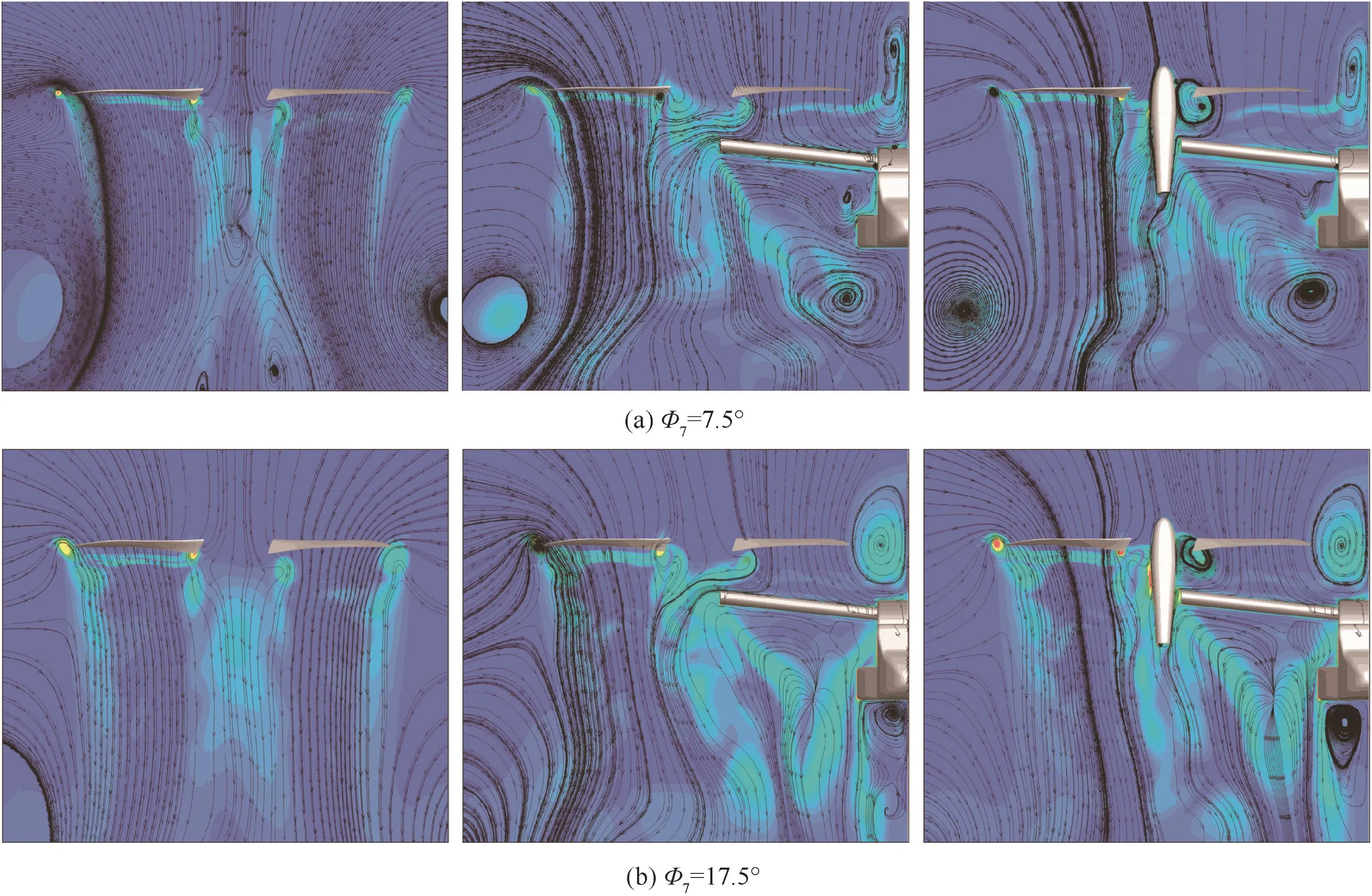
Fig.7 Streamlines and vorticity contour on flow field section at different rotor collective angles.
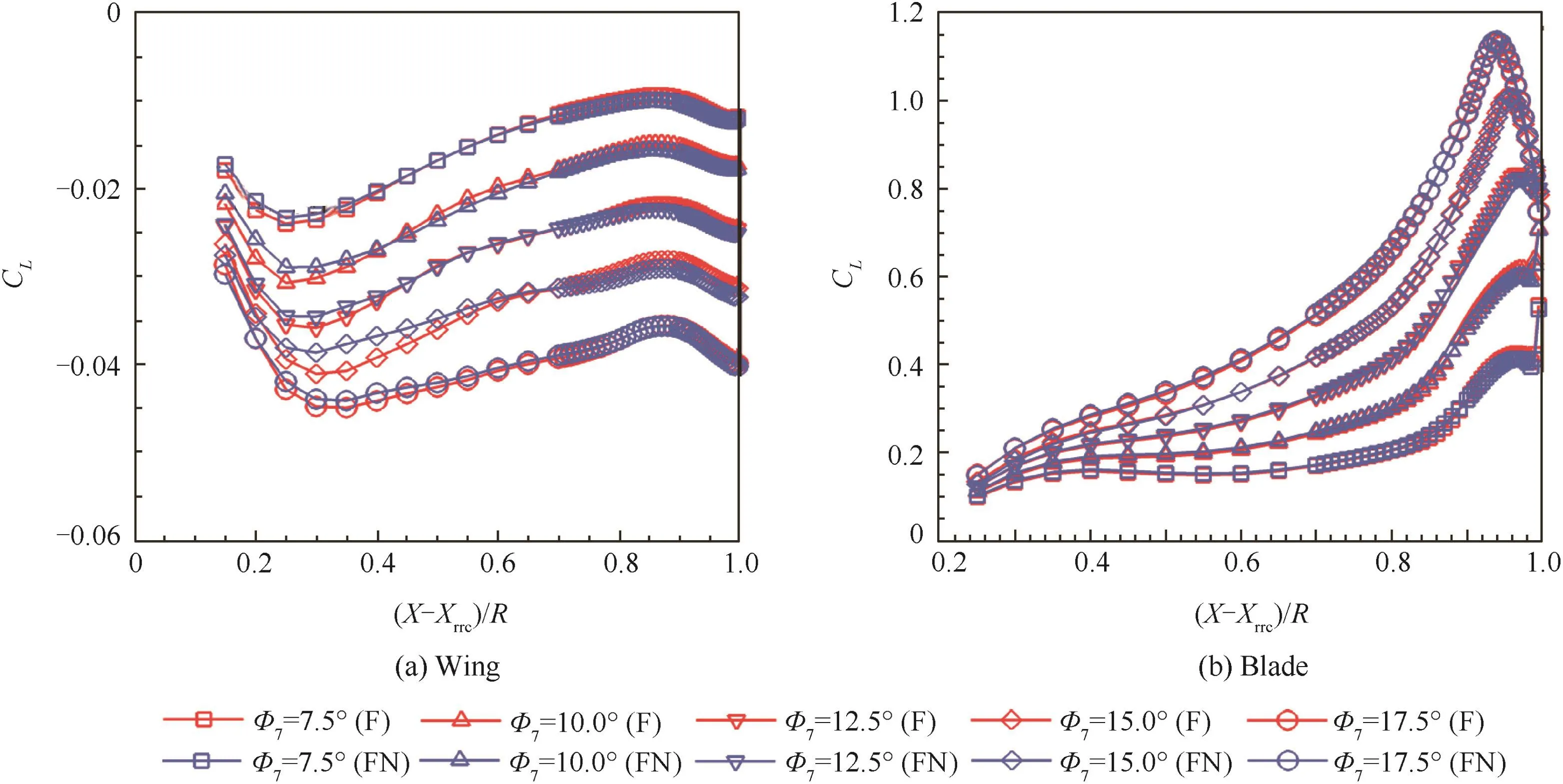
Fig.8 Comparisons of airfoil sectional lift coefficient(with and without nacelle interaction).
Fig.9 is the wing/fuselage surface restricted streamline for different rotor collective angles at blade azimuth ψ =0°( for rotor/wing/fuselage/nacelle model).Theflow stagnation on the wing upper surface moves towards inboard spanwise direction with the collective increasing.This can be explained as with the collective angle increasing,downwash speeds up with relatively less swirl velocity(induced by the rotor,tangential to circumferential direction)variation,which shifts the stagnation point and makes it approach more closely to the blade tip.Similar characteristics are also observed at other blade azimuth angles and not given here.
The separated flow region beneath the wing is represented in Fig.10.The cutting plane is at(X-Xrrc)/R=0.5.It can be seen from this figure that the unsteady separated flow phenomenon is captured with presented unsteady unsteady Reynolds averaged Navier-Stoke methods and turbulence model.Maybe other more suitable turbulence model or DES/LES method will be tried for better demonstration.Despite this limitation,the method,in its current state of development,can provide a useful tool for the study of separation induced by rotor and wing/fuselage interaction.
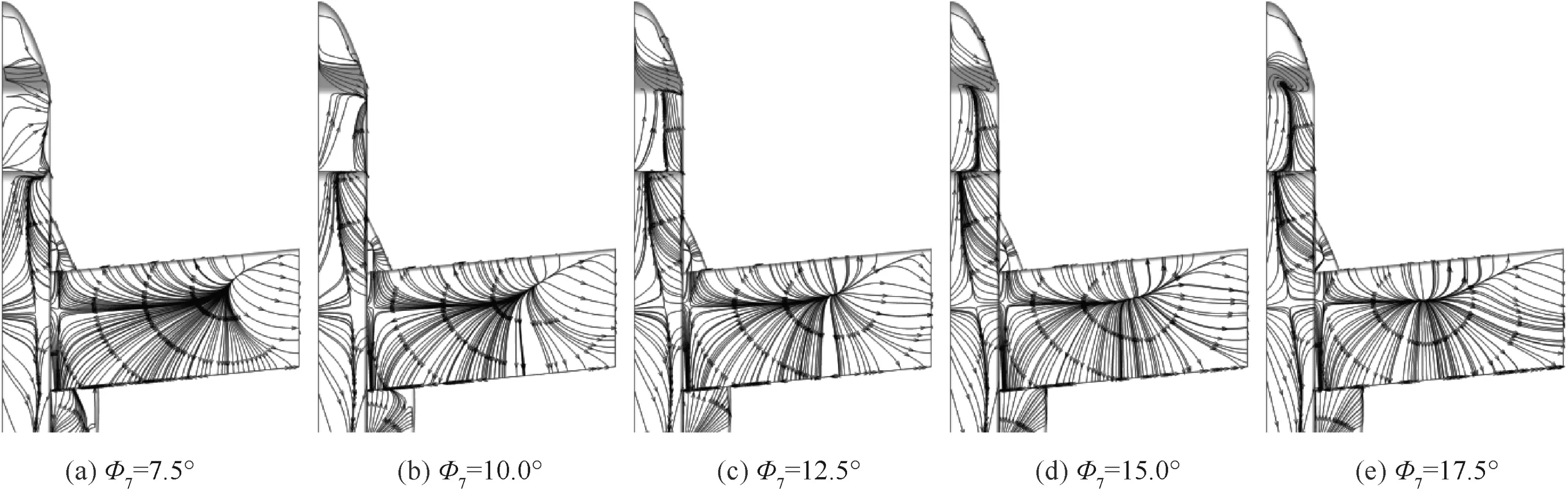
Fig.9 Wing/fuselage surface restricted streamline(ψ =0°).

Fig.10 Streamline in cutting plane((X-Xrrc)/R=0.5,ψ =0°).
Figs.11 and 12 show sectional CLdistribution over blade sections with rotor collective angle Φ7=10.0°,15.0°and differentazimuth angles. The unsteady aerodynamic phenomenon is obvious for rotor/wing/fuselage interaction.Load of the blade changes intensely with the azimuth angle ψ varying from 0°to 360°.It is worthwhile to pay attention that the CLdecreases dramatically at blade tip sections when the blade moves via the azimuth 270°and 300°,where the blade is just above the wing.CLloss of the blade tip sections may be attributed to the ‘fountain flow” effect.We can also observe that time-accurate CLat these two azimuth angles is larger than time-averaged results in one rotational revolution for those blade sections which arefar from the tip region(r<0.75R),and this benefit may be obtained from the‘ground effect” which is provided by the wing/fuselage.In general,the blade CLbenefit obtained from ground effect cannot counteract the loss at the blade tip sections in most work status(can also be seen in thefollowing rotor thrust comparison).The similar characteristics are also observed at other rotor collective angles and not given here.
Fig.13 shows the comparisons of trust coefficient CTvariations of a blade interacted by wing/fuselage/nacelle with the isolated rotor cases in one revolution,where ‘W” represents‘with wing/fuselage and nacelle”,and ‘I” represents ‘isolated rotor”.Fig.14 is sectional Cpcomparison of the blade at different azimuth angles with wing/fuselage/nacelle interaction(Φ7=10°).It can be seen from Fig.13 that CTin interaction cases is smaller when compared with the corresponding isolated rotor blade results from azimuth approximately 180°–330°.This phenomenon is mainly attributed to the lift loss in blade tip region.The tendency reverses at other blade azimuth angles,and the conversion point shows little difference with rotor collective angle variation.Fig.14 gives the pressure difference between upper and lower aerof oil surface of blade tip sections at different blade azimuth,and the azimuth 270°case is smaller compared with azimuth 0°.The pressure coefficient is the pressure divided by the local section dynamic pressure.Besides,it can befound out from thefigure that the rotor experienced lift loss(near the wing/fuselage)and recovery(far from the wing/fuselage)process in per revolution.
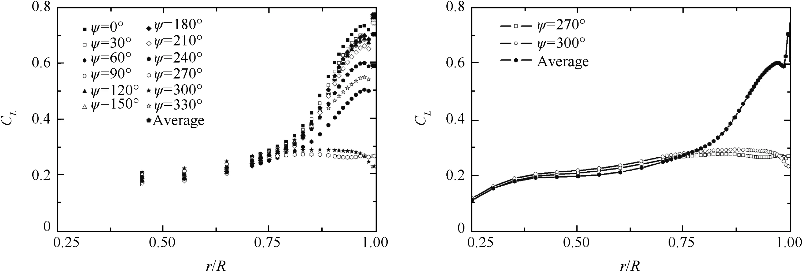
Fig.11 Comparison of spanwise lift coefficient over blade sections at different blade azimuth(Φ7=10.0°).
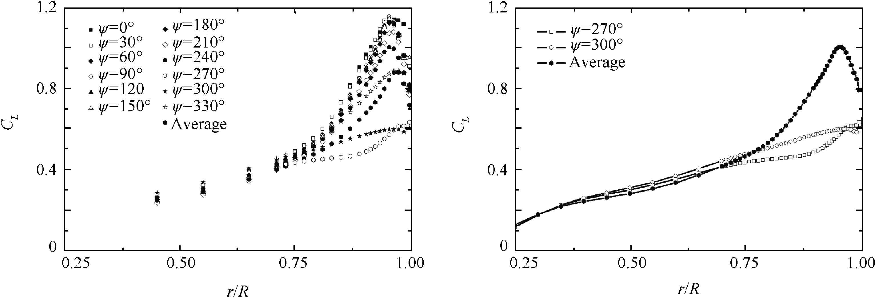
Fig.12 Comparison of spanwise lift coefficient over blade sections at different blade azimuth(Φ7=15.0°).
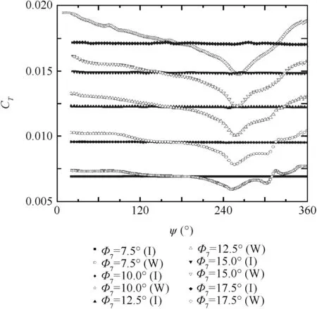
Fig.13 CTcomparison of one blade with/without wing/fuselage/nacelle interference in a rotor revolution.
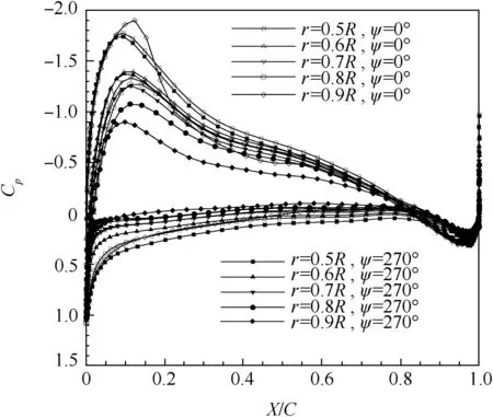
Fig.14 Sectional pressure coefficient comparison of blade at different azimuth angles with wing/fuselage interaction(Φ7=10.0°).
Fig.15 is pressure contour of fuselage at different blade azimuth with Φ7=15.0°( for rotor/fuselage/nacelle model).The static pressure of the wing surface is larger at the blade azimuth 30°and 60°,which is due to the reason that the 3rd blade is close to the wing(azimuth 270°/300°)at this time,and the downwash induced by the blade leads to the increase of the wing surface Cp.
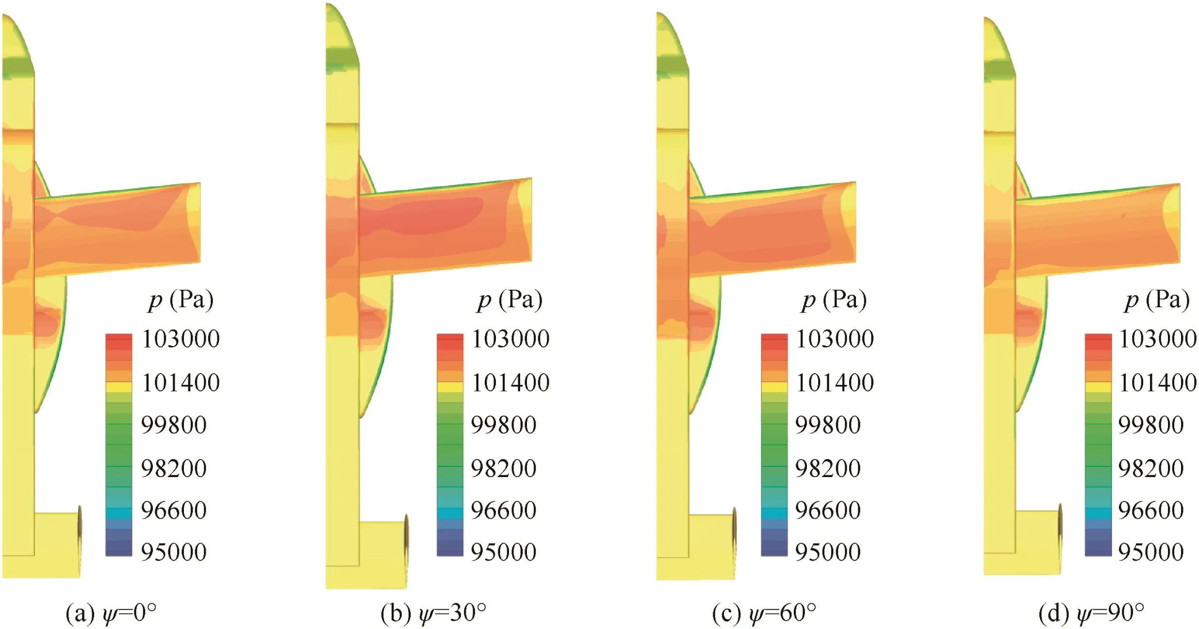
Fig.15 Wing/fuselage surface pressure contour comparisons at different blade azimuth(Φ7=15.0°).
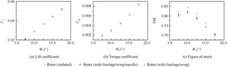
Fig.16 Per formance comparisons of rotor with/without interaction.

Fig.17 Download of wing/fuselage.
Fig.16 presents the calculated rotor lift coefficient,torque coefficient and figure of merit(FM).From Fig.16(a),wefind that the lift data point is entangled when the rotor is with or without wing/fuselage interaction.The rotor lift(with wing/fuselage/nacelle interaction)is 1.5%larger in magnitude than isolated rotor results in Φ7=17.5°and 1.3%smaller in Φ7=15.0°,and the regular pattern is hard to find.Rotor torque solutions obtained from interaction status are consistently higher than the isolated rotor results(Fig.16(b)),which is mainly attributed to the stagnation effect of the wing/fuselage on the swirl of the rotor wake.The maximum amplitude is 3.3%increasing when compared with isolated rotor results for Φ7=7.5°.Accordingly,figure of merit(FM,Fig.16(c))decreases in most cases when the rotor interacts with other components.The FM peak value is approximately 0.84 for isolated rotor in Φ7=10.0°.When the other components are taken into account,the induced drag increasing rapidly with inconspicuous lift variation follows the collective augmentation and brings out over 2.5%FM loss for optimum rotor design point(decreased by about 1.6 percent from the isolated rotor performance in Felker and Light’s experiments26),and the calculated figure of merit with nacelle interaction is little larger than that without at smaller rotor collective angle.
Fig.17 is download of the wing/fuselage.The lift coefficient of the wing/fuselage CLWincreases with the rotor collective angle augmentation.It is also found that the ratio of wing/fuselage download to rotor thrust CL/CTincreases with the rotor collective augmentation in our computation,which indicates more severe aerodynamic loss in those work status with large rotor collective angles.The smaller ratio of wing/fuselage download to rotor thrust is obtained when the nacelle is taken into account(can also be seen from Fig.8 and corresponding analysis).The rotor download on the wing/fuselage of a tilt rotor can be as large as 14%–19%of the rotor thrust,which is similar to Felker and Light’s experimental data27(approximately 15%).
4.Conclusions
(1)The aerodynamic interaction phenomenon of a tilt rotor in helicopter mode is simulated at different rotor collective angles.The aerodynamic differences are compared with each other when the different component combinations are taken into account and the actuation mechanism is discussed.
(2)Thrust of the blade oscillates intensely in one rotor revolution when the rotor interacts with wing/fuselage/nacelle.The blade sectional thrust at the near tip region decreases and is lower than the isolated rotor results in magnitude when the blade traverses through the region(azimuth angle)upon the wing/fuselage,where the incidence angle of blade sections may be decreased by the induced effect of ‘fountain flow” which marks the tilt rotor aircraft flow phenomenon in helicopter mode,and thrust recovers at other azimuth angles where the blade is far from the wing/fuselage and is larger than isolated rotor results(which are mainly influenced by the‘ground effect” provided by the wing/fuselage).
(3)The rotor torques obtained in interaction status are larger in magnitude when compared with the isolated rotor results atall collective angles we have computed.The regular pattern is hard to befound when the rotor lift results in different work status with and without interactions are compared.The thrust loss of blade tip sections is severe and cannot be counteracted by the advantages obtained from the ‘ground effect”byour computations.The rotor figure of merit, for most cases,decreases with aerodynamic interaction.Wing/fuselage download lower the total thrust level for a tilt rotor aircraft.The ratio of wing/fuselage download to rotor thrust increases from approximately 14%to 19%with the rotor collective angle augmentation for our computational operations.
(4)The nacelle has an important influence on the aerodynamic interaction.A strengthened vortex in the region near wing tip and below the rotor is generated,which provides a proximate attraction actuation among the blades and the wing,and notably affects the wing lift and rotor figure of merit.
(5)The multi-level embedded grids and extended holefringe method can work well when coupled with overall‘donor searching”/automatic ‘hole cutting”technique,making the complicated grid assembly with multi-component successful and less laborious.The major flow feature of rotor/wing/fuselage interaction for the tilt rotor aircraft configuration,which includes the vorticity evolution,‘fountain flow” phenomenon and the separated turbulenceflow beneath the wing/fuselage,can be described with limited grid cell numbers,which indicates that the present numerical methods are effective for flow field simulation of tilt rotor in helicopter mode.
Acknowledgements
We would like to express my appreciation to Guo CP and Zhang XL for their assistance in codes compiling during the research.
1.Smith MJ,Ahuja KK,Fleming A.Computational and experimental simulations of tiltrotor configurations in hover.Reston:AIAA;1994,Report No.:AIAA-1994-0735.
2.Kjellgren P,Hassan A,Sivasubramanian J,Cullen L,Cerchie D,Wygnanski I.Computations and experiments of flows around the wing.Reston:AIAA;2002,Report No.:AIAA-2002-6007.
3.Lee-Rausch EM,Biedron RT.Simulation of an isolated tiltrotor in hover with an unstructured overset-grid RANS solverProceedings of the 65th annual forum of the American Helicopter Society.Alexandria:The AHS International,Inc.;2009.
4.Gupta V,Baeder JD.Investigation of quad tiltrotor aerodynamics in forward flight using CFD.Reston:AIAA;2002,Report No.:AIAA-2002-2812.
5.Sitataman J,Baeder JD.Analysis of quad tilt rotor blade aerodynamic loads using coupled CFD/freewakeanalysis.Reston:AIAA;2002,Report No.:AIAA-2002-2813.
6.Potsdam MA,Strawn RC.CFD simulation of tiltrotor configurations in hoverProceedings of the 58th annual forum of the American Helicopter Society.Alexandria:The AHS International,Inc.;2002.
7.Li P,Zhao QJ.Calculations on the interaction flowfield and aerodynamic force of tiltrotor/wing in hover.Acta Aeronaut Astronaut Sin 2013;35(2):361–71[Chinese].
8.Liu Q.Numerical analysis on tiltrotor aircraft flowfield in hover and forward flight[dissertation].Nanjing:Nanjing University of Aeronautics and Astronautics;2008[Chinese].
9.Li P,Zhao QJ,Zhu QX.CFD calculations on the unsteady aerodynamic characteristics of a tilt-rotor in a conversion mode.Chin J Aeronaut 2015;28(6):1593–605.
10.Lee Y,Baeder JD.Implicit hole cutting—A new approach to overset grid connectivity.Reston:AIAA;2003,Report No.:AIAA-2003-4128.
11.Meakin R.Object X-rays for cutting holes in composite overset structured grids.Reston:AIAA;2001,Report No.:AIAA-2001-2537.
12.Wang B,Zhao QJ,Xu G,Xu GH.A new moving embedded grid method for numerical simulation of unsteady flow-field of the helicopter rotor in forward flight.Acta Aerodyn Sin 2012;30(1):14–21[Chinese].
13.Sitaraman J,Floros M,Wissink A,Potsdam M.Parallel domain connectivity algorithm for unsteady flow computations using overlappingand adaptivegrids.J ComputPhys2010;229(12):4703–23.
14.Madrane A,Heinrich R,Gerhold T.Implementation of the chimera method in unstructured hybrid DLR finite volume Taucode6th overset composite grid and solution technology symposium.
15.Bonet J,Peraire J.An alternate digital tree(ADT)algorithm for 3D geometric searching and intersection problems.ASME Int J Numer Methods Eng 1991;31(1):1–17.
16.Zhang Y,Ye L,Yang S.Numerical study on flow fields and aerodynamics of tilt rotor aircraft in conversion mode based on embedded grid and actuator model.Chin J Aeronaut 2015;28(1):93–102.
17.Roe PL.Approximate Riemann solvers,parameter vectors,and difference schemes.J Comput Phys 1981;43(2):357–72.
18.Venkatakrishnan V.On the accuracy of limiters and convergence to steady state solutions.Reston:AIAA;1993,Report No.:AIAA-1993-0880.
19.Spalart PR,Allmaras SR.A one-equation turbulence model for aerodynamic flows.Reston:AIAA;1992,Report No.:AIAA-1992-0439.
20.Zhao HY,He XZ,Le JL.Recursive box method for wall distance computation.Chin J Comput Phys 2008;25(4):427–30[Chinese].
21.Luo H,Baum JD.A fast,matrix-free implicit method for computing lowMach number flows on unstructured grids.Reston:AIAA;1999,Report No.:AIAA-1999-3315.
22.Hermanns M.Parallel programming in Fortran 95 using OpenMP.Spain:Universidad Polite´cnica de Madrid;2002.
23.Sharov D,Nakahashi K.Reordering of 3-D hybrid unstructured grids for vectorized LU-SGS Navier-Stokescomputations.Reston:AIAA;1997,Report No.:AIAA-1997-2102.
24.Turner EL,Hu H.A parallel CFD rotor code using OpenMP.Adv Eng Sof tw 2001;32(8):665–71.
25.Ruffin SM,O’Brien D,Smith MJ,Hariharan N,Lee JD,Sankar L.Comparison of rotor-airframe interaction utilizing overset and unstructured grid techniques.Reston:AIAA;2004,Report No.:AIAA-2004-0046.
26.Felker FF,Light JS.Aerodynamic interactions between a rotor and wing in hover.J Am Helicopter Soc 1988;33(2):53–61.
27.Felker FF,Light JS.Rotor/wing aerodynamic interaction in hoverProceedings of the 42nd annual forum of the American Helicopter Society.Alexandria:The AHS International,Inc.;1986.
Ye Liang is a senior engineer in AVIC Aerodynamics Research Institute.He received his doctor’s degree in aircraft design from Nanjing University of Aeronautics and Astronautics in 2009.His main area of research is CFD on rotor aircraft.
Zhang Ying received the master’s degree in computational fluid dynamics from Beihang University in 2011,and then became an engineer in AVIC Aerodynamics Research Institute.Her main research interest is CFD.
Yang Shuo is an engineer in AVIC Aerodynamics Research Institute.She received the master’s degree in aircraft design from Beihang University in 2012.Her current research interest is CFD.
Zhu Xinglin is an engineer in AVIC Aerodynamics Research Institute.His main research interest is CFD.
Dong Jun is a prof essor of engineering in AVIC Aerodynamics Research Institute.His main research interest is CFD.
15 January 2015;revised 25 January 2016;accepted 26 April 2016
Available online 22 June 2016
Aerodynamic interaction;
Extended holefringe;
Multi-layer embedded grid;
Navier–Stokes equations;
Tilt rotor
©2016 Chinese Society of Aeronautics and Astronautics.Production and hosting by Elsevier Ltd.Thisisan open access article under the CC BY-NC-ND license(http://creativecommons.org/licenses/by-nc-nd/4.0/).
*Corresponding author.
E-mail addresses:yeliang1981@163.com(L.Ye),zyzq6583@126.com(Y.Zhang),feifei427@126.com(S.Yang),zhuxlin2005@sina.com(X.Zhu),dongsavo@hotmail.com(J.Dong).
Peer review under responsibility of Editorial Committee of CJA.
Production and hosting by Elsevier
http://dx.doi.org/10.1016/j.cja.2016.06.001
1000-9361©2016 Chinese Society of Aeronautics and Astronautics.Production and hosting by Elsevier Ltd.
This is an open access article under the CC BY-NC-ND license(http://creativecommons.org/licenses/by-nc-nd/4.0/).
杂志排行

CHINESE JOURNAL OF AERONAUTICS的其它文章
- Investigation of MHD power generation with supersonic non-equilibrium RF discharge
- Experimental study on ceramic membrane technology for onboard oxygen generation
- Transition study of 3D aerodynamic configures using improved transport equations modeling
- Numerical investigation of aerodynamic flow actuation produced by surface plasma actuator on 2D oscillating airfoil
- Characterization of component interactions in two-stage axial turbine
- Numerical study of aerodynamic characteristics of FSW aircraft with different wing positions under supersonic condition