Investigation of MHD power generation with supersonic non-equilibrium RF discharge
2016-11-24YngPengyuZhngBilingLiYiwenWngYutinDunChengduoFnHoGoLing
Yng Pengyu,Zhng Biling,Li Yiwen,c,*,Wng Yutin,Dun Chengduo,Fn Ho,Go Ling
aScience and Technology on Plasma Dynamics Laboratory,Air Force Engineering University,Xi’an 710038,China
bChina Aerodynamics Research and Development Center,Mianyang 621000,China
cScience and Technology on Combustion,Internal Flow and Thermo-Structure Laboratory,Astronautics School,Northwestern Polytechnical University,Xi’an 710072,China
Investigation of MHD power generation with supersonic non-equilibrium RF discharge
Yang Pengyua,b,Zhang Bailinga,Li Yiwena,c,*,Wang Yutiana,Duan Chengduoa,Fan Haoa,Gao Linga
aScience and Technology on Plasma Dynamics Laboratory,Air Force Engineering University,Xi’an 710038,China
bChina Aerodynamics Research and Development Center,Mianyang 621000,China
cScience and Technology on Combustion,Internal Flow and Thermo-Structure Laboratory,Astronautics School,Northwestern Polytechnical University,Xi’an 710072,China
Magnetohydrodynamic(MHD)power generation with supersonic non-equilibrium plasma is demonstrated.Capacitively coupled radio frequency(RF)discharge(6 MHz,maximum continual power output of 200 W)was adopted to ionize the Mach number 3.5(650 m/s),0.023 kg/m3airflow.In a MHD channel of 16 mm×10 mm×20 mm,MHD open voltage of 10 V is realized in the magnetic field of 1.25 T,and power of 0.12 mW is extracted steadily and continuously in the magnetic field of 1 T.The reasons for limited power generation are proposed as:low conductivity of RF discharge;large touch resistance between MHD electrode and plasma;strong current eddies due to flow boundary layer.In addition,the cathode voltagefall is too low to have obvious effects on MHD power generation.
1.Introduction
The development of Magnetohydrodynamics(MHD)technology provides an innovative way to solve the important technical problems in hypersonic flight.The AJAX was presented by Russian scholar and caused that MHD technology applied to aircraft became a research hot spot.1–6The key of AJAX is that the temperature and velocity of flow entering into the engine are decreased by MHD power generation and reach the requirement of engine’s stable work in hypersonic flight.7–12
The working medium of MHD power generation is conductiveflow,so air needs to be ionized into plasma.There are two ionizing ways:equilibrium and non-equilibrium ionization.Equilibrium ionization requires a very high gas temperature,which is hard to realize in flight.Non-equilibrium ionization has no temperature requirement and is a morefeasible.In general,it can be realized by strong electric filed or high energy electron beam.13–16
Currently,the experimental study of MHD power generation with non-equilibrium plasma is in preliminary stage.Murray et al.realized the experimental observation of MHD power generation.17They ionized supersonic airflow with discharge driven by 2 ns,100 kHz,30 kV pulsed voltage,and achieved Mach number 3 supersonic non-equilibrium plasma.Faraday generator with continuous electrodes was adopted and the peak extraction power measured by optical isolation was about 4.2 mW.At the same time,Nishihara et al.also conducted similar experimental study.18They measured the MHD open voltage of 25-30 V,but extraction power could not be measured.In addition,producing supersonic non-equilibrium plasma for MHD applications was also experimentally studied.Bobashev et al.investigated the production of air(nitrogen)gas-discharge plasma in a supersonic MHD channel using a combined discharge consisting of a high-frequency discharge and a high-voltage pulse discharge.19McAndrew et al.designed and tested a supersonic plasma wind tunnel where the plasma was produced by a 50 kW,1 ms pulse of microwave radiation at 2.45 GHz.20
These studies have employed pulse discharge to ionize airflow,but their results present some unsolved problems.First,the cathode voltagefall is significant,and Faraday current is seriously limited when MHD voltage is lower than the cathode voltagefall.Second,the pulse discharge plasma leads to a discontinuous power generation and low time-average extraction power due to thefast delay of plasma.Third,the pulse discharge voltage and current coupling into MHD circuit lead to very strong interference,and the weak signal of extraction power is hard to capture.Thus the extraction power was not measured directly in Munetake Nishihara’s experiment.And in Murray’s experiment,the extraction power was measured by adding a bias voltage into MHD circuit and adopting optical isolation between MHD and measurement circuit.
Pulse discharge seriously limits MHD power extracting according to above studies,and to our best knowledge,the continuous MHD power generation from supersonic nonequilibrium plasma has not been realized till now.Thus it is very necessary to investigate MHD power generation with continuous discharge.This paper tries to produce volume-filling,steady,and continuous non-equilibrium plasma in supersonic airflow employing capacitively coupled radio frequency(CCRF)discharge,and conducts continuous MHD power generation.In addition,thefactors limiting the performance of MHD power generation are analyzed by experimental and numerical methods.
2.Experimental system
The supersonic non-equilibrium plasma was produced by CCRF discharge in the supersonic airflow realized within a small-scale,in-draft wind tunnel facility.The image of discharge was monitored by two cameras.Faraday MHD channel with continuous electrodes was designed to extract power.The room of MHD channel was full of uniform magnetic field produced by an electromagnet.The value of extraction power was obtained through measured load voltage.
2.1.Wind tunnel
Mach number 3.5 airflow was achieved through a converging/diverging nozzle.Test cross section was 10 mm×20 mm.Wind tunnel worked in an in-draft setup using a vacuum system to realize the low backpressure.Employed reducing valve adjusted the pressure of nozzle’s inlet down to 40 kPa resulting in the airflow of the Mach number 3.5(650 m/s),0.023 kg/m3through the test section,and the stable running time was 15 s.
2.2.Plasma production
Continuous and steady non-equilibrium plasma was produced by CCRF discharge.The power supply is an AG1017L radio frequency(RF)voltage generator with a maximum continual power output of 200 W and a range of frequency from 10 kHz to 10 MHz.The discharge electrode was made of Al2O3ceramic and its surface was placed on a 10 μm thick palladium(Fig.1).The Palladium metal was separated from the plasma by the ceramic piece.There was a match circuit between RF power and discharge electrodes.The match circuit was composed of two 35 mH inductances which connected with each electrode,respectively.The optimal match was realized at the radio frequency of 6 MHz.As the variation of load characters could change the original optimal match,the radio frequency has to be slightly adjusted to recover the optimal match.
2.3.MHD electrode
MHD electrode was made of copper.Some problems were considered to design MHD electrodes.Firstly,MHD electrodes need to touch the plasma.The images of RF discharge in static air gas and supersonic airflow are shown in Fig.2.It can be seen that the bright region does not move forward following supersonic air.In other word,stronger ionization region,where the plasma is dense,is still located in the room covered by the discharge electrodes.In addition,the nonequilibrium plasma life time is at the order of 1 μs in weak electric field,21–23making the plasma sparse in other region.Thus MHD electrodes were deposed at the room covered by the discharge electrodes to touch plasma.
Secondly,MHD electrodes could affect the distribution of discharge electric field,and result in a sharp local ionization between MHD electrode and discharge electrode.The local ionization is hard to control especially under higher pressure,but we can take effort to decrease the possibility of its production.One of the means is to increase the distance between discharge electrode and MHD electrode by reducing the width of MHD electrode.
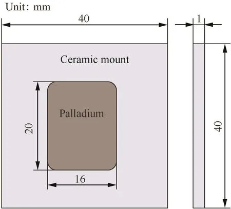
Fig.1 Schematic of discharge electrode.
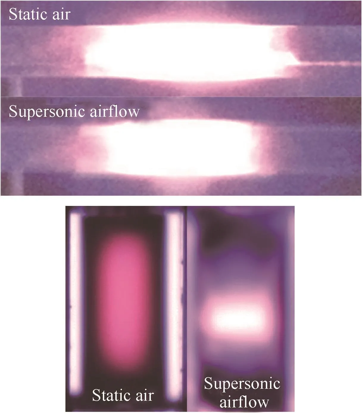
Fig.2 RF discharge images in vertical flow and in parallel flow.
Thirdly,a large touch resistance is produced by bad touching between MHD electrode and plasma,and it can critically decrease the Faraday current.As shown in Fig.2,when static air is trans formed into supersonic airflow,the stronger ionization region shrinks.In supersonic airflow,discharge cannot ensure the rich plasma near the top and down walls,which probably leads to a large touch resistance.To improve the bad touch,MHD electrodes need to stretch into the airflow,and it must be ensured that MHD electrodes do not seriously disturb supersonic flow field.In summary,MHD electrodes’structure,size and position were designed(Fig.3,B is the magnetic field).
2.4.MHD circuit design and generation voltage measurement
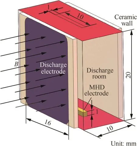
Fig.3 Schematic of MHD channel.
The steady running time of experimental system reached 10 s,in which MHD channel acted as a battery.The MHD electrodes were connected with a load resistance.Load voltage was measured by the Tek-DPO4104 oscilloscope and the Tek-P6139A voltage probe.In addition,it must be considered that the electrical noisefrom the CCRF discharge,combined with the interaction of the discharge electrodes and the MHD electrodes,as coupled through the plasma,covered the signal of extraction power.MHD generation voltage was a few of volt under the experimental condition and was far lower than the electrical noise of about 100V.However,MHD generation power was a DC signal and electrical noise was an AC signal from CCRF discharge.Thus the component of generation voltage could be separated from measurement signal by averagefiltering.In addition,electrical noise was effectively reduced by a 1 μF filtering capacity.
3.Results and discussion
3.1.Supersonic plasma characteristic
The image of CCRF discharge in Mach number 3.5 supersonic air flow is shown in Fig.4 where the discharge load power(LP)is 25 W and the magnetic field B is 1 T.It can be seen that the RF discharge is more uniform compared with the condition in non-magnetic field(Fig.2).The reason is that Lorentz force can reduce the diffusion loss of charge particles.The strong ionization regions are located in central area of MHD channel and the cathode layers near discharge electrodes.Ionization strength gradually reduces toward top and down walls.There are dark regions near top and down walls due to low RF load power and the effect of flow on discharge.In the dark regions,discharge ionization has already been very weak and local plasma is only remained by the diffusion of plasma from central area.In addition,the discharge region,specifically cathode layer,is vertically asymmetric due to the non-uniform flow field.
The discharge load voltage and current are measured by Tek-P6015A voltage probe and Tek-TCP312 current probe respectively(Fig.4).Both the voltage and current are sine waves and do not distort,which can infer that the discharge is steady and the characteristic of discharge load does not seriously change.Thus the plasma’s density and distribution are steady.
Judging from the above experimental phenomenon,we can see that the discharge plasma is steady,continuous,and relatively uniform in Mach number 3.5 supersonic airflow,B=1 T,which is the basis for analysis of MHD power generation in experiment and forgiving the boundary condition of numerical simulation.
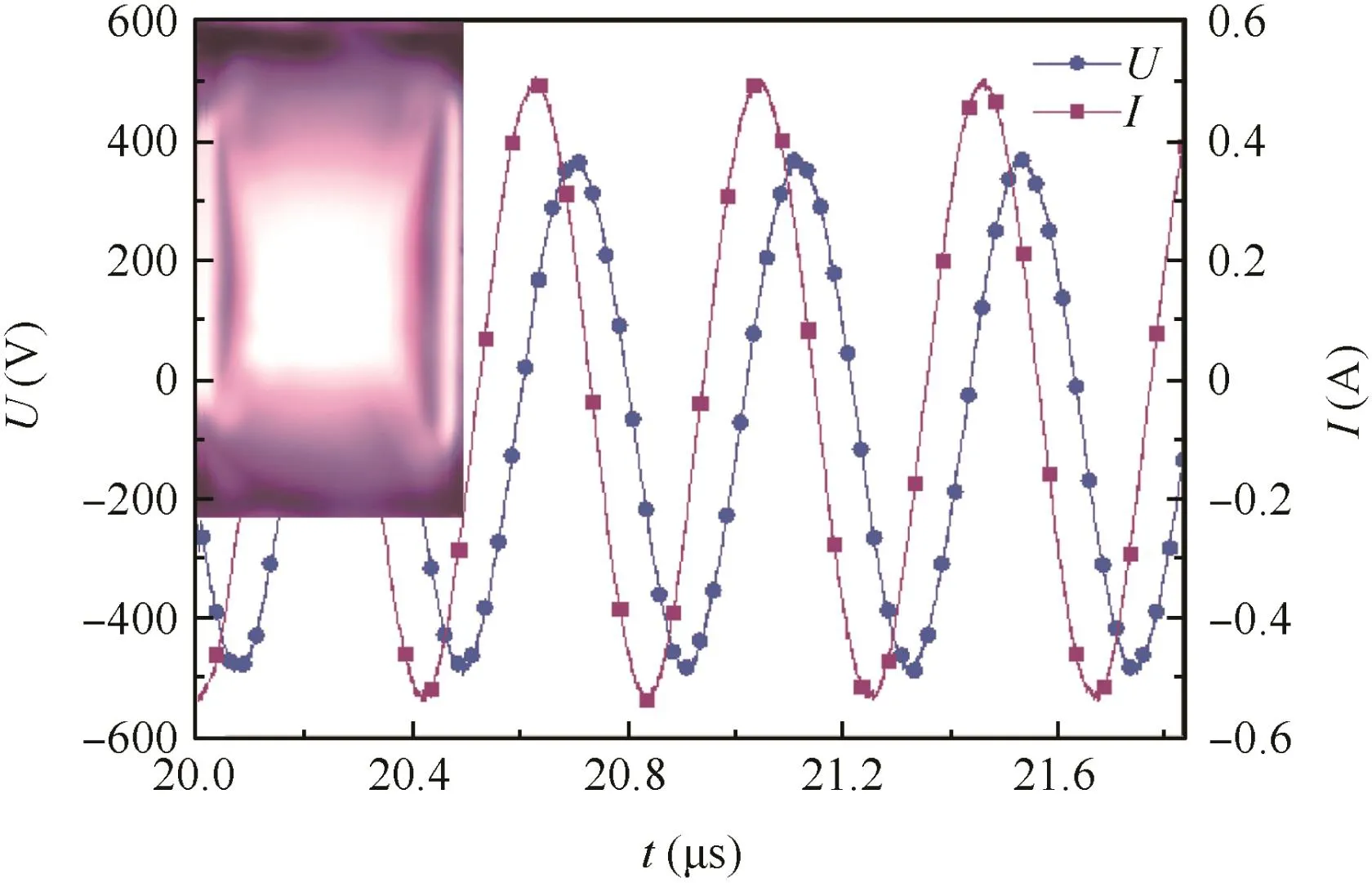
Fig.4 Image of RF discharge and voltage and current curves of discharge in Mach number 3.5 supersonic airflow(LP=25 W,B=1 T).
3.2.MHD open voltage and extraction power
With different magnetic strengths and directions,MHD open voltages were obtained by measuring the voltages between MHD electrodes without load resistance.The results show that the absolute value of MHD open voltage is large as magnetic strength increases and reaches 10 V when B=1.25 T.On the other hand,the phase of open voltage reverses to negative when magnetic direction changes.These disciplines are consistent with the theoretical formula U=huB where h is the distance between MHD electrodes,u the velocity of flow in x direction,and U theinducevoltage.Ath=18 mm,u≈650 m/s,B=1.25 T,the induced voltage is about 14.6 V.
At B=1 T and different LP,MHD load voltages Uoare obtained by measuring the voltages between MHD electrodes with connecting a 20 kΩ load resistance Ro.The results are shown in Fig.5.It can be seen that the voltage waves are composed of a DC signal and sine signal.The sine signal is the electronic noise which is produced by RF discharge and leaks into MHD circuit as coupled through the plasma.But due to the 1uF filtering capacity parallel connected with MHD electrodes,the amplitude of sine signal has been seriously reduced from 100 V to a few of Volts.The DC signal presents the value of extraction voltage.The extraction voltage becomes gradually large as LP increases,because the increase of LP enhances the discharge ionization and raises the plasma conductivity,which reduces the internal resistance of MHD channel.On the other hand,the amplitude of sine signal is also gradually large as LP increases.The reason includes two points.First,the discharge voltage and current increase as LP increases.Second,the couple between MHD circuit and RF discharge circuit enhances with the increase of plasma conductivity.
Extraction voltage Uecan be estimated by time-average load voltage.As shown in Fig.5,at LP=35 W,extraction voltage greatly increases.The reason is analyzed according to corresponding images of the discharge.At LP<35 W,there are dark regions near top and down walls.The dark regions make MHD electrodes insulated from the central strong ionization region where is full of plasma.The thickness of dark regions gradually reduces as LP increases.At LP≥35 W,the dark regions nearly disappear and MHD electrodes touch strong ionization region directly.Thus it can be considered that dark regions are very low conductive due to poor plasma and lead to a large touch resistance between MHD electrodes and plasma.The large touch resistance seriously limits Faraday current Ie.As LP increases,the central strong ionization region penetrates the dark regions and rich plasmas touch MHD electrodes,which sharply decreases the touch resistance.
Thus it is important for extraction power to guarantee effective touch between MHD electrodes and rich plasma.In current experiment,to reduce the negative effect of dark region,MHD electrodes were stretched into the airflow(Fig.3).But in order to reduceflow disturbance produced by MHD electrodes,the stretching distance was merely 1 mm,smaller than the thickness of dark region at LP<35 W.On the other hand,a volume-filling discharge was realized by increasing LP to guarantee the effective touch.But the volume-filling discharge is unsteady and easily trans forms to local discharge because the air density in boundary layers is lower than that in coreflow region.In current experiment,unsteady discharge phenomenon has emerged at LP≥35 W.For example,the wave shape of load voltage has distorted and the strong discharge has been produced at the top and down boundary layers(Fig.5).
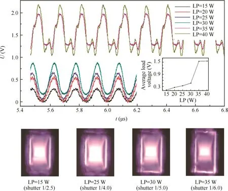
Fig.5 MHD load voltage waves and corresponding images of discharge at B=1 T and different discharge load power(LP).
Using measured extraction voltage,Faraday current can be calculated by the formula Ie=Ue/Ro,and extraction power can be calculated by the formula Pe=Ue2/Ro.The results are shown in Table 1,and the achieved maximum extraction power is 0.12 mW.
3.3.Cathode voltagefall and internal resistance
Ohio State University’s Nishihara et al.has conducted a similar experimental study of MHD power extraction.18In their experiment,a repetitively pulsed discharge with pulse duration(FWHM)of approximately 30 ns was adopted in order to ionize the Mach number 3 airflow into conduction flow.They did not realize power extraction and only measured open voltage about 25–30 V.From their analysis,the reason is that the open voltage is much smaller than the cathodefall of about 500 V under their experimental conditions,which leads to a very low Faraday current.In addition,Princeton University’s Murray et al.also presented the negative effect of cathodefall by the experimental and numerical studies in which the plasma was also produced by the repetitively pulsed discharge.17
From the obtained measurement data(Fig.5),it is difficult to observe cathodefall.Thus a new experiment is conducted to measure cathodefall.In static air of 600 Pa pressure,a DC power is adopted to provide the voltage between MHD electrodes.And the voltage–current characteristics of MHD channel are measured in the presence of CCRF plasma and in the absence of CCRF plasma,respectively(Fig.6).It can be seen that two curves are nearly linear,but the points of intersection with voltage-axis are different.The value of cathodefall can be estimated by the points of intersection.The red curve nearly passes through the zero point of voltage-axis and the black curve nearly passes through the 420 V point of voltage-axis.It is indicated that cathode voltagefall is very small when MHD channel is full of RF plasma.Thus it can be concluded that in current experiment of MHD power extraction,cathode voltage is too small to affect Faraday current.In Nishihara’s and Murray’s experiments,cathode voltage is large,and that is because the plasma in MHD channel is not continuous.
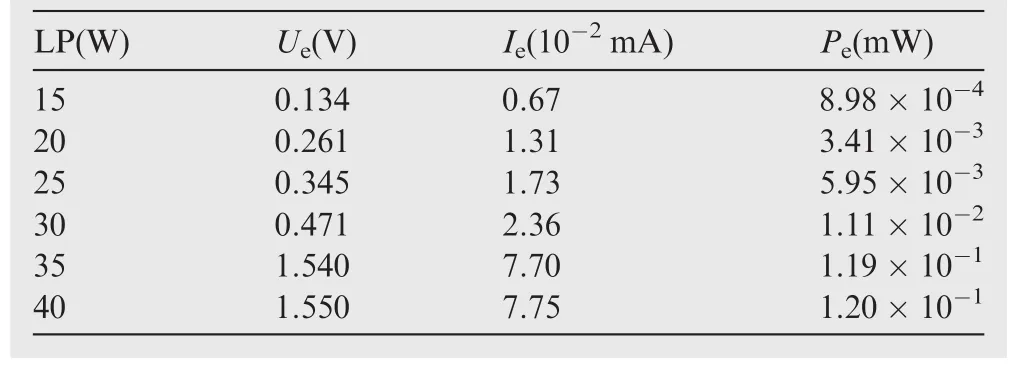
Table 1 Calculated extraction current and power at different LP.
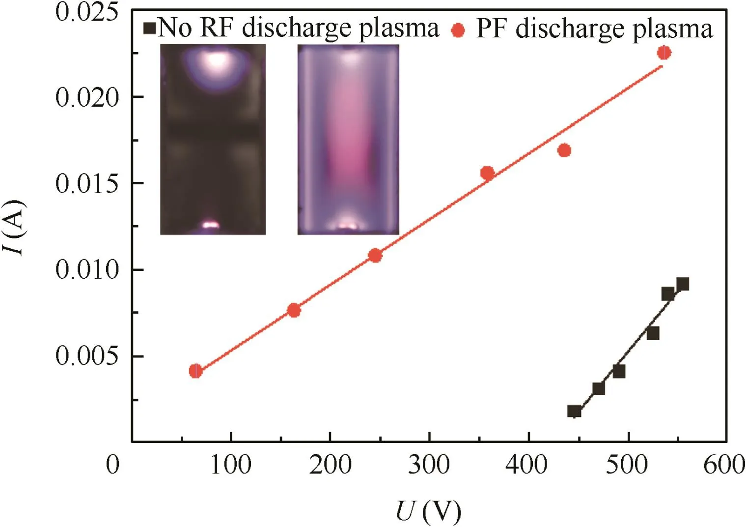
Fig.6 Voltage–current characteristics of MHD channel in static air of 600 Pa pressure.
In addition,the internal resistance of MHD channel Rican be obtained by the linear slope on the current–voltage characteristics,and is about 26000 Ω in the presence of CCRF plasma.The conductivity of RF plasma can be estimated by the formula σ=h/(SRi)where S is the across area of plasma in MHD channel. The calculation result is about 4.3×10⁻³S/m.And in the supersonic air,σ is lower than the value because the discharge power and charge particles lose with following airflow.
The density of extraction power can be estimated by formula ρe=k(1-k)σu2B2,where k is the load coefficient ranging from 0 to 1.When k=0.5,ρereaches the maximum equaling 4.54×10²W/m3at u=650 m/s,B=1 T,and σ=4.3×10⁻³S/m.The maximum theoretical value of Peis about 1.4 mW in MHD channel of the size 3.2×10⁻⁶m3,and is still very small.Thus,to increase extraction power,plasma conductivity must be seriously raised.
4.Numerical simulation
4.1.Solution model
A numerical model is adopted to learn the electric process of MHD channel during power extraction.The numerical model is based on the equations of single fluid MHD,and the equations are simplified according to the experimental conditions.First,on account of the low magnetic Reynolds number flow in MHD channel,the induced magnetic field is neglected,i.e.,the magnetic field of MHD channel is the constant equaling provided magnetic field at experiment.Second,on account of the low magnetic interactive parameter,it is considered that the magnetic force has no effect on the flow field.In addition,the discharge does not produce fierce Joule heating,so the temperature rise of flow field leaded by the discharge can be neglected.Similarly,the heating effect of Faraday current on flow field also can be neglected.In summary,it is considered that the flow field of wind tunnel will not change with the present of magnetic field and CCRF discharge,which is verified by the experimental observation that the static pressure of supersonic flow in MHD channel measured by an absolute pressure trans former did not change under the in fluence of abovefactors.Thus flow field can be independently solved by neglecting magnetic force and Joule heat.The flow field of wind tunnel is simulated by CFD code,and the velocity field of MHD channel is obtained.
When an electrically neutral fluid is considered,the Ohm’s law of MHD can be described by the formula

In the formula,the electromagnetic quantities include the magnetic field B,electric field E,and current density j.U is the velocity of flow.In addition,β is the Hall parameter.In current experiment,Bx=0,By=0,and Bz=const.The equivalent electrical conductivity which is a tensor puts forward
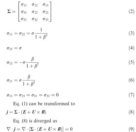
The relationship between the electric potential φ and electric field E satisfies the formula

Eq.(9)can be trans formed by Eqs.(2)and(10)to
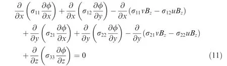
The Poisson Eq.(11)is discretized by central difference scheme.And the Gauss–Seidel iterative computation is used to solve electric potential.
4.2.Grid and boundary condition
The geometric model is similar to experimental MHD channel(Fig.7).The part of MHD electrodes that stretch into the flow field is not considered to simplify the structure grid and solution code.The size of the integration domain is 16 mm in x-axis(the width of discharge electrode),20 mm in y-axis and 10 mm in z-axis.The domain only has a block that consists of 50×50×50 grid points.
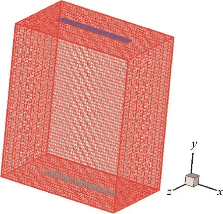
Fig.7 Geometric modeling of MHD channel.
For boundary conditions,Eq.(12)is applied to the cathode boundary,Eq.(13)is applied to the anode boundary,and other boundaries adopt Eq.(14).
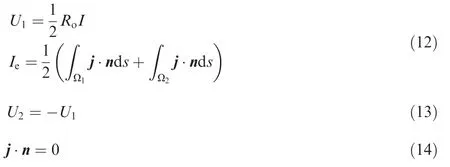
where Ω1is the superficial area of cathode,Ω2the superficial area of anode,and n the unit normal vector of the surface.It is assumed that the electrical conductivity σ and Hall parameter β are uniform,and σ =4.3 × 10⁻³S/m,β =0.1,respectively.The velocity field of MHD channel U is from the solution result of CFD code.In corresponding to experimental condition,Bz=1 T and Ro=20 kΩ.
4.3.Simulation results
According to the experimental condition,the wind tunnel’s flow field is simulated by CFD code.The solution results are shown in Fig.8.It can be seen that the flow field in MHD channel is uniform and the maximum flow velocity reach Mach number 3.3 which is smaller than the designed Mach number 3.5 because of the thicker boundary layer.In addition,the discharge electrodes’effect on flow field is also reduced due to the thicker boundary layer.The second flow is produced by the high pressure regions near top and down walls,and the boundary layer of the side walls permeates toward core flow region and thickens as flow develops.
The potential distribution in MHD channel is simulated(Fig.9).It can be seen that potential distribution is slightly distorted at xOy profile because of Hall effects.The maximum and minimum potential are 3.23 V and-3.16 V,respectively.The potential of MHD electrodes is±0.807 V,so it can realize extraction voltage Uo=2×0.807 V=1.614 V,Faraday current Ie=Uo/Ro=8.07×10-2mA,and extraction power Po==1.3×10⁻¹mW.In addition,the Joule loss can be computed by the formula
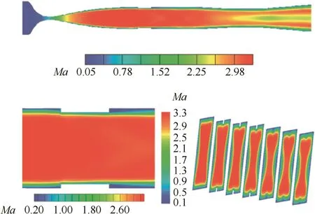
Fig.8 Mach contours in wind tunnel.
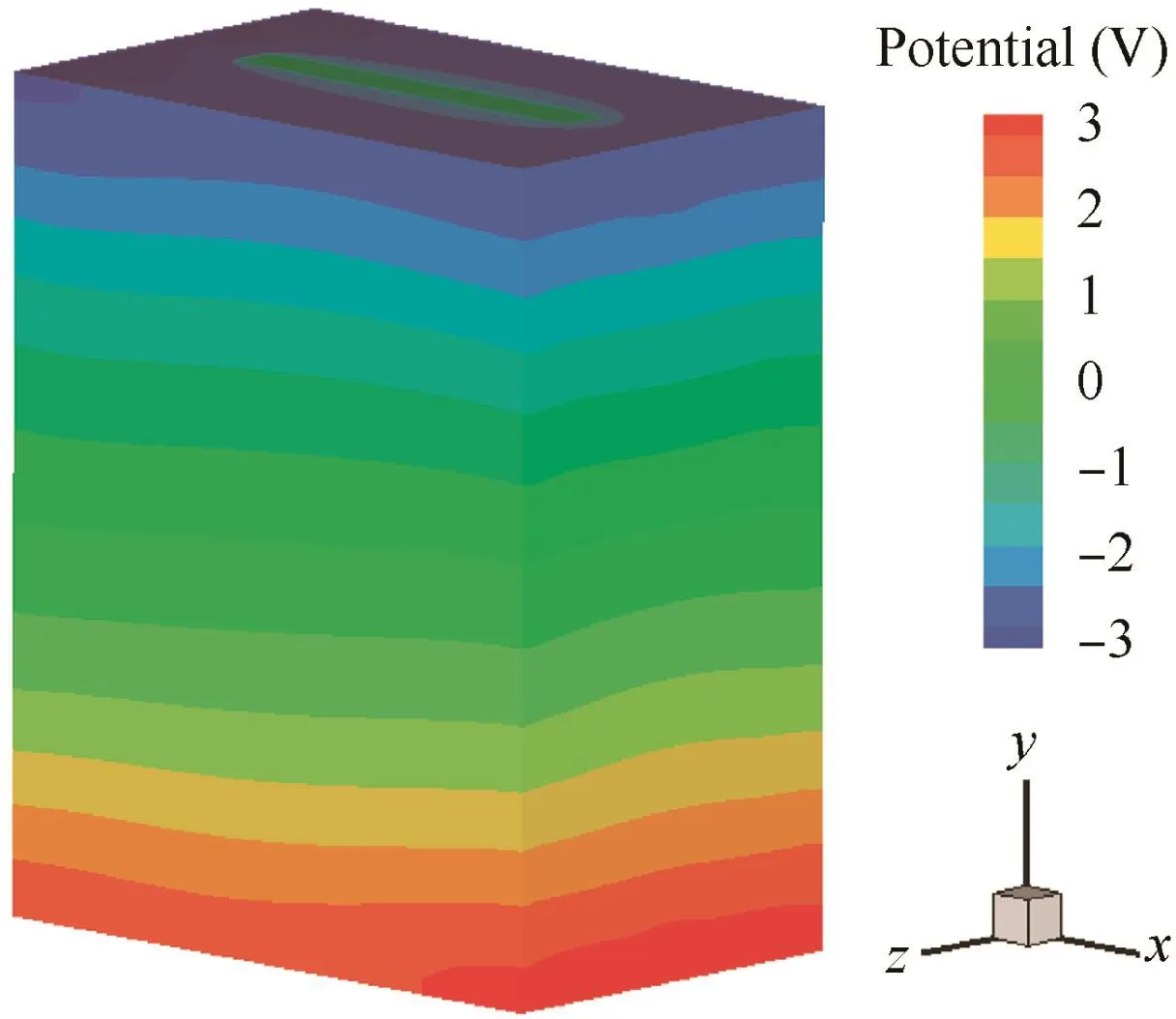
Fig.9 Potential distribution in MHD channel.
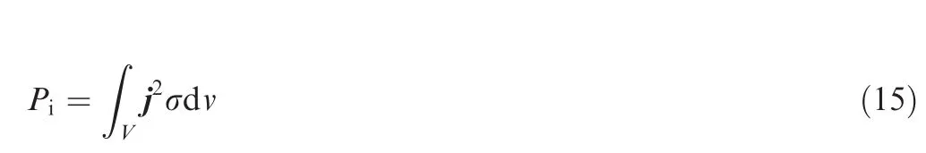
where V is the volume of MHD channel.The current density distribution is computed by Eqs.(8)and(10).The computed result of the Joule loss is 1.6 mW.The extraction efficiency is computed by η=Po/(Po+Pi)=7.5%.
The current density distribution and current lines of MHD channel’s middle pro files are shown in Fig.10.It can be seen that the maximum current density located in MHD electrodes’edge and corner is about 16 A/m2.It is found that the current eddies produced in MHD channel is an important reason for higher Joule loss.The current eddies are mainly at yOz pro file and xOz pro file.At yOz pro file,current eddies are located in boundary layers of left and right walls,and are stronger.Its production mechanism is that the small flow velocity of x direction in boundary layers leads to small induced electric field in the locality,which does not counteract the main static electric field produced by the difference of potential between top and down walls.So the reversed current is produced by the static electric field in boundary layers,thus leads to current eddies.
At xOz profile,current eddies cover the whole xOz profile,which is different from the current eddies of yOz profile.The reason is that there is no external current loop composed of MHD channel and load circuit,and there is only the internal current loop composed of middle region and boundary layer.Its production mechanism agrees with the above analysis,and it needs to be emphasized that the current eddies of xOz profile are driven by the electric fields in x direction,which include the induced electric field and static electric field.The electric fields in x direction are produced owing to Hall effects,and increase as Hall parameter increases.On the contrary,the electric fields in y direction decrease as Hall parameter increases.It can be inferred that when Hall effects become notable,the current eddies of xOz profile can be stronger than the current eddies of yOz profile and the performance of power generation can become worse.Of course,Hall effects only change the strength of current eddies,and the essential reason for current eddies’production is the electro-conductive boundary layer.
5.Conclusions
Volume-filling,steady,continuous,relatively uniform,and non-equilibrium plasma was produced in Mach number 3.5 supersonic airflow in the magnetic field of 1 T using capacitively coupled radio frequency(CCRF)discharge.Continuous and steady power generation from supersonic non-equilibrium plasma was realized.The MHD open voltage was about 10 V in the magnetic field of 1.25 T,and the maximum extraction power was about 0.12 mW under the conditions of the magnetic field of 1 T and 20 kΩ load resistance.
The extraction power is very low.The reasons are as follows:(A)the conductivity of RF discharge plasma is merely the order of 1×10⁻³S/m;(B)the touch resistance between MHD electrode and RF discharge plasma is large owning to the dark regions near top and down wall,and the small contact area between electrodes and plasma;(C)in MHD channel,strong current eddy produced due to the boundary layer of flow leads to the serious power loss of Joule heating.Current eddy also reduces the extraction efficiency.In addition,the small scale of MHD generator,the weak magnetic field,and the low velocity of flow all lead to a relative low generation power.On the contrary,experiments proved that in the volume- filling RF discharge,the cathodefall was rather low and would not limit the MHD extraction power.In the present study,it is proved that continuous and steady MHD power generation from non-equilibrium plasma is feasible.But due to the limitation of non-equilibrium ionization,it is difficult to produce high-conductivity and continuous plasma in supersonic air flow.Thus,MHD power extraction from nonequilibrium plasma is not considerable.In addition,solving the problems such as large touch resistance and strong current eddy can effectively improve the performance of MHD power generation,which needs further study of the mechanism of multi- field coupling in MHD channel,including discharge electric field, flow field,magnetic field and induced electric field.
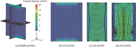
Fig.10 Current density distribution and current lines of MHD channel’s middle profiles.
Acknowledgements
This study was co-supported by the National Natural Science Foundation of China(No.11372352)and the Shaanxi Province Science Foundation of China(No.2013JQ1016).
1.Gurijanov E.AJAX-New directions in hypersonic technology.3rd AIAA international space plane and hypersonic systems and technology conference.Reston:AIAA;1996.
2.Chase R,Boyd R,Czysz P.An AJAX technology advanced SSTO design concept.AIAA and SAE,1998 world aviation conference.Reston:AIAA;1998.
3.Lyu HY,Zhen HP,Li CX,Zhang YN.Influence of cross-sectional shape on the performance of supersonic magnetohydrodynamic generator.Acta Aeronaut Astronaut Sin 2015;36(11):3549–56.
4.Kuranov A,Kuchinsky V,Sheikin E.Scramjet with MHD control under ‘AJAX”concept– requirements for MHD systems.32nd AIAA plasma dynamics and lasers conference.Reston:AIAA;2001.
5.Kuranov A.MHD control on hypersonic aircraft under ‘AJAX”concept-Possibilities of MHD generator.40th AIAA aerospace sciences meetingamp;exhibit.Reston:AIAA;2002.
6.Kuranov A.MHD control by external and internal flows in scramjet under AJAX concept.41st aerospace scienes meeting and exhibit.Reston:AIAA;2003.
7.Kuranov A,Korabelnikov A.Atmospheric cruiseflight challenges for hypersonic vehicles under the AJAX concept.J Propul Power 2008;24(6):1229–47.
8.Kuranov A,Sheikin E.Magnetohydrodynamic control on hypersonic aircraft under AJAX concept.J Spacecraft Rockets 2003;40(2):174–82.
9.Kuranov A.Hypersonic technologies of atmospheric cruiseflight under AJAX concept.15th AIAA international space planes and hypersonic systems and technologies conference.Reston:AIAA;2008.
10.Sheikin EG,Kuranov AL.Scramjet with MHD by pass under‘AJAX” concept.42nd AIAA aerospace sciences meeting and exhibit.Reston:AIAA;2004.
11.Tang J,Yu D,Bao W.A new manner for energy reintroduction in AJAX.IEEE computational engineering in systems application.Piscataway,NJ:IEEE Press;2006.p.803–8.
12.Tang J,Bao W,Yu D.The In fluence of energy-bypass on the performance of AJAX.44th AIAA aerospace sciences meeting and exhibit.Reston:AIAA;2006.p.78–80.
13.Macheret S.External supersonic flow and scramjet inlet control by MHD with electron beam ionization.39th aerospace sciences meeting and exhibit.Reston:AIAA;2001.
14.Nishihara M,Adamovich IV.Numerical simulation of a crossed pulser-sustainer discharge in transverse magnetic field.IEEE Trans Plasma Sci 2007;35(5):1312–24.
15.Yang PY,Zhang BL,Li YW,Zhang Y.Experimental study of the discharge characteristic of nanosecond voltage pulses in supersonic flow.Acta Aeronaut Astronaut Sin 2014;35(6):1539–48.
16.Deaconu S,Jones J,Hawk C.Diagnostics of electric properties of flowing microwave plasmas for MHD applications.35th joint propulsion conference and exhibit.Reston:AIAA;1999.
17.Murray R,Zaidi S,Carraro M.Magnetohydrodynamic power generation using externally ionized,cold,supersonic air as working fluid.AIAA J 2006;44(1):119–27.
18.Nishihara M,Rich W,Lempert W.MHD flow control and power generation in low-temperature supersonic flows.Am Phys Soc 2006;1:347–55.
19.Bobashev SV,Erof eev AV,Lapushkina TA.Air plasma produced by gas discharge in supersonic MHD channel.44th AIAA aerospace sciences meeting and exhibit.Reston:AIAA;2006.
20.McAndrew B,Barker P,Miles R.Development of a supersonic plasma wind tunnel.38th AIAA aerospace sciences meeting and exhibit.Reston:AIAA;2000.
21.Aleksandrov N,Kirpichnikov A,Kindusheva S.Non-equilibrium plasma life time measurements and flow control.45th AIAA aerospace sciences meeting and exhibit.Reston:AIAA;2007.
22.Zhukov V,Kindisheva S,Kirpichnikov A.Plasma production for MHD power generation by nanosecond discharge.44th AIAA aerospace sciences meeting and exhibit.Reston:AIAA;2006.
23.Kline J,Zaidi S,Murray R.Non equilibrium ionization techniques for MHD power extraction in high-speed flows.41st AIAA aerospace sciences meeting and exhibit.Reston:AIAA;2003.
Yang Pengyu received the M.S.degree in Air Force Engineering University in 2014,and then became an assistant engineer of China Aerodynamics Research and Development Center.His main research interest is aeronautic flow control using magnetohydrodynamics and plasma dynamics techniques.
Zhang Bailing is a prof essor in Air Force Engineering University.His area of research includes aeroengine ground test and hypersonic vehicle MHD technique.
Li Yiwen is an assistant in Air Force Engineering University.His main research interest is hypersonic vehicle MHD technique and MHD wind tunnel.
23 June 2015;revised 17 October 2015;accepted 15 March 2016
Available online 13 July 2016
Magnetohydrodynamic;
Non-equilibrium plasma;
Power generation;
Radio frequency discharge;Supersonic flow
©2016 Chinese Society of Aeronautics and Astronautics.Production and hosting by Elsevier Ltd.Thisisan open access article under the CC BY-NC-ND license(http://creativecommons.org/licenses/by-nc-nd/4.0/).
*Corresponding author at:Science and Technology on Plasma Dynamics Laboratory,Air Force Engineering University,Xi’an 710038,China.
E-mail addresses:xiaoyu182444840@126.com(P.Yang),zhangbailing2468@126.com(B.Zhang),lee_yiwen@163.com(Y.Li).
Peer review under responsibility of Editorial Committee of CJA.
Production and hosting by Elsevier
http://dx.doi.org/10.1016/j.cja.2016.06.018
1000-9361©2016 Chinese Society of Aeronautics and Astronautics.Production and hosting by Elsevier Ltd.
This is an open access article under the CC BY-NC-ND license(http://creativecommons.org/licenses/by-nc-nd/4.0/).
杂志排行

CHINESE JOURNAL OF AERONAUTICS的其它文章
- Numerical simulation of aerodynamic interaction for a tilt rotor aircraft in helicopter mode
- Experimental study on ceramic membrane technology for onboard oxygen generation
- Transition study of 3D aerodynamic configures using improved transport equations modeling
- Numerical investigation of aerodynamic flow actuation produced by surface plasma actuator on 2D oscillating airfoil
- Characterization of component interactions in two-stage axial turbine
- Numerical study of aerodynamic characteristics of FSW aircraft with different wing positions under supersonic condition