Numerical investigation of aerodynamic flow actuation produced by surface plasma actuator on 2D oscillating airfoil
2016-11-24MinhKhangPhanJichulShin
Minh Khang Phan,Jichul Shin
Department of Aerospace Engineering,University of Ulsan,Ulsan 680-749,Republic of Korea
Numerical investigation of aerodynamic flow actuation produced by surface plasma actuator on 2D oscillating airfoil
Minh Khang Phan,Jichul Shin*
Department of Aerospace Engineering,University of Ulsan,Ulsan 680-749,Republic of Korea
Numerical simulation of unsteady flow control over an oscillating NACA0012 airfoil is investigated.Flow actuation of a turbulent flow over the airfoil is provided by low current DC surface glow discharge plasma actuator which is analytically modeled as an ion pressure force produced in the cathode sheath region.The modeled plasma actuator has an induced pressure force of about 2 kPa under a typical experiment condition and is placed on the airfoil surface at 0%chord length and/or at 10%chord length.The plasma actuator at deep-stall angles(from 5°to 25°)is able to slightly delay a dynamic stall and to weaken a pressure fluctuation in down-stroke motion.As a result,the wake region is reduced.The actuation effect varies with different plasma pulse frequencies,actuator locations and reduced frequencies.A lift coefficient can increase up to 70%by a selective operation of the plasma actuator with various plasma frequencies and locations as the angle of attack changes.Active flow control which is a key advantageous feature of the plasma actuator reveals that a dynamic stall phenomenon can be controlled by the surface plasma actuator with less power consumption if a careful control scheme of the plasma actuator is employed with the optimized plasma pulse frequency and actuator location corresponding to a dynamic change in reduced frequency.
1.Introduction
Flow control in either passive or active manner is still an attractive research area especially in dynamic situation such as in oscillating airfoil.A major attention has been paid to thefact that dynamic stall phenomenon has been a limiting factor in aerodynamic performance of aerial vehicles such as rapid maneuvering aircraft and bio-inspired aircraft or with rotating blades in helicopters(retreating blades1)or wind turbines.Eliminating or reducing the effect of dynamic stall phenomenon would provide many benefits to possibly build a high performance aerial vehicle which requires severe mobility,adaptability and flexibility features for various missions under heavy dynamic loading with noise and vibration.Aiken et al.2pointed out that if dynamic stall phenomenon can be eliminated,a next generation helicopter,a stall-free rotor helicopter,would be possible to realize.In addition,success in design of bio-inspired wing can bring many benefits by lowering cost and reducing pollution and noise during take-of f.Dynamic stall has been investigated by many researchers using either experimental or computational methods.Surface pressure measurement of unsteady boundary layer flow and stall event on oscillating NACA0012 airfoil revealed that dynamic stall can be signatured by a sudden turbulent breakdown and is highly sensitive to a reduced frequency(k=ωc/2U∞)which is a non-dimensional value defined by the ratio of pitching velocity ωc/2 to free-stream velocity U∞,where c is a chord length and ω an angular velocity.Lift stall occurs when the leading edge vortex(LEV)covers 90%of the chord length,while moment stall begins when trailing edge reversal flow ends to upwards spread.3Study on vortex structures in a downstream of a flow past an oscillating NACA0012 airfoil reported that dynamic stall can be controlled by manipulating frequency,amplitude and sharpness of oscillating wave form.4They claimed that the axial flow in the center of wake vortices is important and its magnitude is suggested to be linearly dependent on oscillating frequency and amplitude of Karman vortex.Numerical simulation5about dynamic stall for low Reynolds number(Re)2D flow provided a good quantitative agreement with experimental data except at very high angle of attack(AOA).Predicting a flow separation phenomenon precisely is still challenging problem in a numerical study.Experimental data about dynamic stall phenomena for eight airfoil sections over a wide range of incidence angles,amplitudes,oscillating frequencies,and Mach numbers are collected by McAlister et al.6,but still a limited number of experiment cases are available.The above mentioned studies propose that dynamic stall begins with flow separation at leading edge of oscillating airfoil during its rapid motion near high AOA.Then it is followed by LEV which afterwards grows and covers the entire upper surface of the airfoil.Hence,capturing flow phenomena like vortex growth,propagation and subsequent separation is essential for better understanding of dynamic stall.Eventually,dynamic stall phenomena should be controlled by providing appropriate flow control techniques to control LEV and flow separation.Here,an active flow control is desired in dynamic situation in an effort to suppress or delay the effect of dynamic stall.
So far,numerous passive and active flow control methods have been proposed.However,applying some of them in dynamic situations requires caution due to some of their reversing effects on parasitic drag,additional weight,centrifugal loading,noise and vibration.7Especially the structure of these aircrafts of ten consists of composite material that limits a structural modification for the provision of control devices.Desired way to improve an aerodynamic performance in stall flow is to delay or postpone the onset of dynamic stall with the minimized side effects described above rather than to mitigate its effects after occurrence.Although control flow using passive devices has some advantages such as simplicity,robustness,lower cost,and efficient and quickest devices to implement,8–10it also has disadvantages such as increased weight,induced noise and vibration,surface contamination and parasitic drag.Because of these disadvantages,many researches have been focusing on performance optimization.Godard and Stanislas7tested co-and counter-rotating vortex generator with different geometries(height,separation distances,triangular and rectangular devices,pitch and skew angle).However,parasitic drag and vibration is still unavoidable and the actuation effect cannot be controlled in a timeaccurate manner.On the other hand,activeflow control compared with passive control can per form a transient flow control whereflow properties can be modified in a time-dependent manner rather than in a permanent way.Shun and Ahmed10used air jet vortex generators(AJVG) for activeflow control to improve performance of wind turbine.AJVG with a series of holes on the airfoil surface was helpful to reduce an area of flow separation associated with dynamic stall phenomena on wind turbine blade.Geissler et al.11computationally investigated an activeflow control of rotor blades with a trailing edgeflap.Nevertheless,it can be intuitively seen that applying such mechanical control devices as AJVG or the actuators based on active material to rotating blades is still complicated.
Alternative technique to mechanical flow control that had been studied in the past decade is a plasma actuator.Studies of using plasma actuator in flow control reveal that plasma actuator is capable of producing noticeable results in the application of flow control.Plasma actuator is fully electronic with non-moving parts and consequently do not cause high centrifugal loading in rotating bodies.It is also light,scalable in size and operates at high frequency.12There fore,plasma actuator can be a good candidate for controlling a flow in dynamic situations such as in rotor blades.Flow actuation by plasma actuator can be achieved by gas heating, electrohydrodynamic(EHD) forcing and/or magneto-hydrodynamic(MHD) forcing mechanism.Supersonic flow control can be achieved by an instantaneous gas heating near the wall by high current DC discharge plasma to modify the boundary layer thickness13or by creating a high speed spark-jet impinging through a boundary layer.14Subsonic flow control can be achieved by various types of plasma actuators mostly relying on electrostatic forcing.Lorentz force in the presence of external electromagnetic field can also play a role in flow control.14
In this paper,a numerical investigation about an active flow control on oscillating airfoil using a low current DC surface discharge plasma actuator is reported.EHD force achieved by the plasma actuator is estimated via analytic estimation of ion pressure force produced near the cathode based on the values obtained from the experiment.The EHD force produced right on the airfoil in a tangential direction can effectively provide a slip surface and modifies a boundary layer profile.Modeled plasma actuator is placed on the upper surface of oscillating NACA 0012 airfoil and provides a pulsed actuation source into Navier–Stokes equations.We do the simulation for Reynolds number of 4×10⁶flow over an oscillating NACA0012 airfoil with various values of AOA range,reduced frequencies and plasma frequencies.Effect of the plasma actuator is expected to change the characteristics of formation and propagation of LEV and corresponding flow phenomena in oscillating airfoil.
2.Computational scheme
2.1.Turbulent model
In the context of an oscillating airfoil exhibiting complicated dynamic stall phenomenon,vortex structures and turbulence effect,various computational methods such as hybrid LESRANS,15hybrid URANS-LES,16analytical method17,18and vortex method19are available and tested.These methods are in general more accurate than standard turbulence modeling Reynolds average Navier–Stokes(RANS)but may not be practically efficient when a large number of simulation cases are needed.Correa et al.20claimed that RANS can provide a reasonable 2D prediction of dynamic stall phenomenon and reattachment incidence angles.There fore,we employ RANS method without significantly sacrificing the preciseness of numerical solution with a much reduced computational cost.
Although all real physical phenomena are inherently 3D and dynamic stall studied here is not an exception,2D simulation is per formed in this paper.For flow over an oscillating airfoil,2D simulation will cause larger lift vibration during downstroke phase than 3D simulation.16Although 3D simulation can improve the precision of solution and reduce amplitude of lift fluctuation in down-stroke phase due to an improvement of the hysteresis loop,it is still costly.In addition,2D simulation is still efficient in the studies where large amount of simulation cases are needed for an investigation of the effect of aerodynamic parameters as considered in this paper.Numerical simulation is per formed with an open source CFD code,OpenFOAM.The unsteady solver in OpenFOAM is equipped with an algorithm called ‘PIMPLE”which has two iterative loops to help accelerating convergence and further stabilizing a solution of unsteady flow.First order,bounded,implicitscheme Euler is selected for time discretization.The generalized method of geometric algebraic multi-grid(GAMG)is employed to accelerate solutions on the mesh.According to Ekaterinaris and Platzer,21in comparison with two-equation turbulence models,one-equation turbulence model which is more recently developed isbetterto capture physical phenomenon of unsteady separated flow.Spalart–Allmaras(S–A)turbulence model22is commonplace in commercial simulations.Alexis and Zha23used S–A model in their study on flow control by co- flow jet on pitching airfoil and reported that numerical results agree with the experiments for deep-stall cases.Martinat et al.15showed that S–A model of turbulence phenomenon of the dynamic stall can provide results close to experiment with a slight overestimation of the maximum lift and drag coefficients.Test simulations conducted for a validation of S–A model showed a good agreement with experiment results,and hence we adopted S–A turbulence model for a simulation of dynamic stall phenomena and flow control by plasma actuator in this paper.
2.2.Dynamic mesh
In order to implement a motion of oscillating airfoil,a dynamic mesh technique called ‘Arbitrary Mesh Interface”(AMI)is adopted.As depicted in Fig.1,the computational domain is split into two sub-domains:one stationary zone and one rotary zone.Unstructured mesh is used in thefarfield and structured mesh is employed near the airfoil surface in order to provide a better way to adaptively re-mesh the suction side.21The dynamic zone where the oscillating airfoil is located has a finer mesh compared to that in thefixed zone in order to capture detailed flow phenomena corresponding to a dynamic stall.The dynamic zone is linked together with the static zone using AMI technique through non-con formal interface(Fig.1).The interface has diameter of 40 times of chord length(c=1 m)and is centered at 1/4-chord from the leading edge on the camber mean line.All far-field boundaries are placed at 30c aimed at eliminating wall effect,and thereby a uniform flow is achieved at the inlet and the wakes can fully grow in the downstream.On the inlet boundaries,velocity is set to be free stream velocity according to the desired Reynolds number and pressure is set to have zero gradient,whereas on the outlet boundaries,velocity is set to have zero gradient and pressure is set at atmospheric pressure(101325 Pa).Time step is automatically changed to maintain Courant number less than 0.5 to satisfy stability requirement.Results were taken when the solution reaches a periodic steady state that is achieved in about 4 cycles of oscillation,and hence the results are not time-averaged.
20 layers of meshes are placed inside the boundary layer with a growth rate of 1.125 aimed at having a good resolution of a thin near-wall sub-layer.The heights of the first cell in the boundary layer are determined to have 0.4 mm and 0.5 mm for Reynolds number of 3×10⁶and 4×10⁶,respectively.Corresponding y+equals to 30 which is small enough to resolve a turbulent boundary layer with wall function treatment,and consequently total number of cells can be reduced.The dynamic zone rotates in sinusoidal motion(α0+ α1sin(ωt))so that the airfoil oscillates at the desired rotating frequency(ω). α0and α1are a mean angle and amplitude angle,respectively.It is known24that a key parameter in dynamic stall phenomenon is a reduced frequency.In horizontal wind turbines,reduced frequency is mostly fixed,whereas it varies in helicopters ranging from 0 to 0.08 because the relative velocity changes during a pitching cycle.In this report,we use three linearly increasing values of reduced frequency(k)of 0.05,0.075 and 0.1 to cover a typical range in helicopters.From our hands-on experiences,plasma actuator is mostly effective in a separated flow.There fore,this paper focuses on the cases with deep-stall angles(α0=15°and α1=10°).
2.3.Modeling of plasma actuator
Plasma actuator is modeled as an additional force term(Fp)and added to momentum equation as
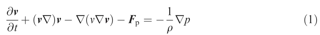
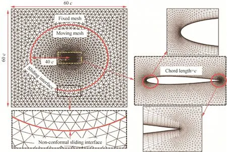
Fig.1 Computational domain and mesh details.
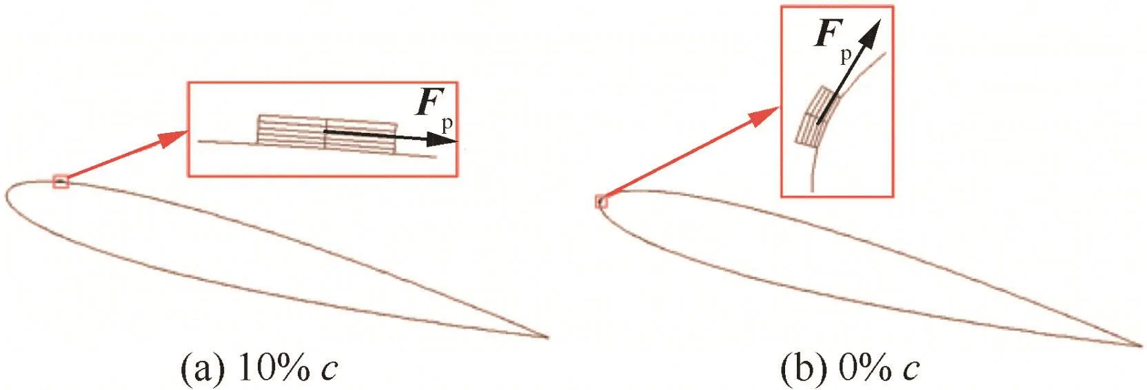
Fig.2 Locations and areas where modeled plasma actuator is placed.
3.Code validation
To ensure the reliability of numerical solution for a simulation of plasma flow control,the mesh and computational schemes are validated for flows over static and dynamic airfoil.Fig.3 compares lift and drag coefficients(CLand CD)obtained by numerical simulation and experiment data24for a stationary NACA0012 airfoil at Reynolds number of 3×10⁶.As shown in the figure,the static stall angle and the lift even at higher angles are well predicted with the mesh and turbulent model used in this study.This implies that the turbulent shear and flow separation are modeled with acceptable accuracy.The computed drag force is slightly over-predicted at low AOAs where a viscous drag dominates over a pressure drag.The same meshing scheme,model and computational schemes are tested for the dynamic cases where an airfoil oscillates over a certain range of AOAs.
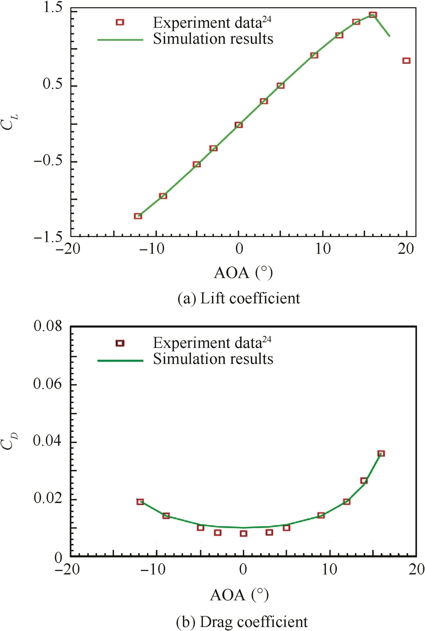
Fig.3 Validation results of lift and drag coefficients for a stationary NACA0012 airfoil.
Figs.4 and 5 provide comparison results for an oscillating airfoil at pre-stall angles(α(t)=5+5sin(ωt))and deep-stall angles(α(t)=15+10sin(ωt)),respectively.Reduced frequencies and Reynolds numbers are 0.1 at Re=4×10⁶and 0.15 at Re=3×10⁶,respectively,which are selected to compare with experiment values.In dynamic situation compared with the static case(Fig.3),there exists a hysteresis in both lift and drag.A shape of the hysteresis loop varies with reduced frequencies and airfoil shapes.Result for the pre-stall case presented in Fig.4 indicates that the tested simulation run shows a good agreement with the other simulation results26where a sophisticated computational approach was implemented.However,these simulation results still exhibit a lower lift slope than experiment results in Ref.6,which implies that the up-to-date computational technique is still limited to predict a precise aerodynamic performance in dynamic situation.Computational results arefound to over-predict a drag coefficient in both up-stoke and down-stroke motion at AOAs lower than a neutral angle(5°).A close prediction of drag coefficient is obtained only for angles from 8°to 10°in up-stroke motion.
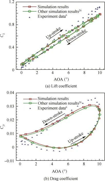
Fig.4 Validation of lift and drag for an oscillating NACA0012 airfoil at pre-stall angles of α(t)=5+5sin(ωt)with reduced frequency of k=0.1 and Re=4×10⁶.
Aerodynamic characteristic in the deep-stall case presented in Fig.5 exhibits a different behavior from the pre-stall case.Major discrepancies are a delayed stall angle,a sudden increase in lift be fore a maximum AOA in up-stroke motion and an oscillatory behavior of lift and drag in down-stroke motion.A delayed stall angle is due to a primary LEV that produces a favorable pressure gradient.3A sudden increase in lift and drag just be fore the maximum AOA is caused by a propagation of secondary vortex over the upper surface.6As the primary and secondary vortices propagate over the upper wing in down-stroke motion,the surface pressurefluctuates and produces an oscillatory behavior in lift and drag.A propagation speed of these vortices depends on reduced frequency and airfoil shape.Referred simulation results(solid line)in Fig.5 are taken from Ref.21where Baldwin-Lomax turbulence model is used and validation results(solid line with square symbol)are calculated with S–A model,while the experiment data arefrom Ref.27.It reveals that both cases are able to capture typical behavior of oscillating airfoil such as a lift jump be fore a stall and oscillatory behavior in down-stroke motion.But there still exists in both cases a significant discrepancy between simulation results and experiment values and it is hard to determine which one provides a better prediction.Marongiu28asserted that there is no theory applicable to solve the aerodynamics of oscillating airfoil with a large magnitude of oscillatory amplitude and computational simulations are very time-consuming to get results close to experiment.Conducting an experiment with time-dependent dynamic conditions is complicated and the experimental data are of ten less precise and detailed to provide a correct comparison between experiment and computation.Many researchers18,21,29–31have examined many computational calculations on oscillating airfoil with various AOA ranges,but the results are still not in good agreement with experiment data.Under this circumstance,the simulation for flow actuation in oscillating airfoil involving a dynamic stall presented in this paper should mainly be used to explore thefeasibility of plasma flow actuator for controlling dynamic stall phenomena and to provide an optimized activeflow control technique.The effectiveness of the plasma flow actuator on modifying a flow structure and hence controlling an aerodynamic performance in oscillating airfoil is simulated at various aerodynamic parameters including reduced frequencies,plasma frequencies and actuator locations.
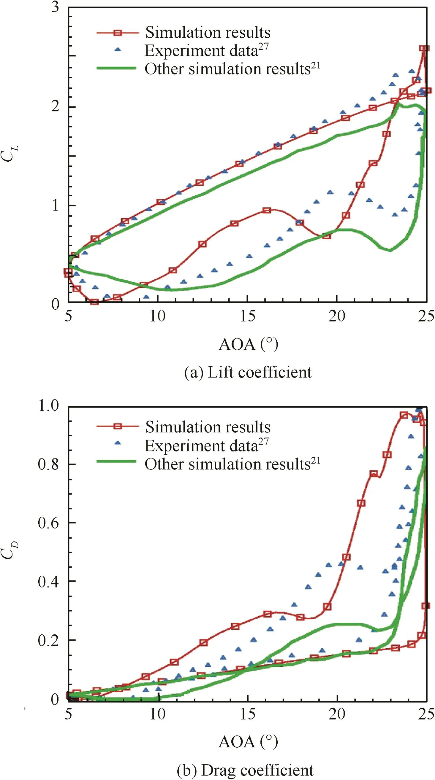
Fig.5 Validation of lift and drag for an oscillating NACA0012 airfoil at deep-stall angles of α(t)=15+10sin(ωt)with reduced frequency of k=0.15 and Re=3×10⁶.
4.Results and discussions
4.1.Effect of plasma actuator on dynamic stall
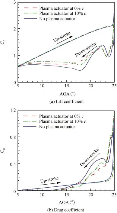
Fig.6 Lift and drag coefficients with and without plasma actuator(k=0.1 and Re=4×10⁶).
Fig.6 shows lift and drag coefficients at deep-stall angles with arangeof AOA from 5° to25° withk=0.1and Re=4×10⁶.Solid curves correspond to the case where the plasma actuator is turned of f.Dashed curves and dot-dashed curves correspond to the cases where the plasma actuator is turned on at 0%c and at 10%c,respectively.As previously shown in Fig.5,a sharp increase in lift and drag in upstroke motion and an oscillatory behavior in down-stroke motion are observed for all cases.Because of different reduced frequencies and Reynolds numbers,the curves are slightly different from those presented in Fig.5.The fluctuation frequency in down-stroke motion is higher than the case shown in Fig.5.When the plasma actuators are kept turned on,they are barely effective in up-stroke motion except near the maximum AOA where a slight delay in rise of lift and drag is observed due to a further acceleration of LEV promoted by the plasma actuator.This infers that a flow actuation may not be necessary for the most period in up-stroke motion and consequently,a passive flow control device loses its advantage in up-stroke motion resulting in an increase in dynamic loading and noise/vibration.In down-stroke motion,the presence of the plasma actuator produces overall a higher lift and smaller drag.Interesting observation is that the onset of fluctuation in down-stroke motion is delayed and the oscillation amplitude is reduced,resulting in a weakened fluctuation in the presence of plasma actuator.The plasma actuator at 0%c produces a higher lift at angles around 18°but causes a higher drag at lower AOAs.The plasma actuator at 10%c produces a higher lift at angles between 16°and 5°but causes a higher drag at angles between 25°and 20°in down-stroke motion.Actuation effect in up-stroke and down-stroke motion observed in Fig.6 infers that a flow actuation in dynamic situation is better to be operated in an active manner so that the desired actuation authority can be addressed at specific times and locations.Simple example of flow control sequence based on the result in Fig.6 can be as follows.
(1)Turn of f plasma actuator in up-stroke motion.
(2)Turn on the plasma actuator at 0%c at higher AOAs than 18°.
(3)Turn of f the plasma actuator and turn on the plasma actuator at 10%c at lower AOAs than 18°.
Simulation results for an activeflow control will be presented in the next section.
Important aerodynamic characteristics in oscillating airfoil are governed by formation and propagation of vortex structures.Hence,the flow actuation must target to control these vortices.Fig.7 shows vorticity profiles for plasma-of f case(left column)and plasma-on cases(center column:0%c,right column:10%c)with a reduced frequency of 0.1 and plasma pulsefrequency of 1 kHz.Arrow indicates a direction of pitching motion(up-stroke or down-stroke).In all three cases,there exists a strong vortex near the leading edge very close to the upper surface be fore reaching a maximum AOA.This LEV is responsible for a delay in stall angle in dynamic situation.At 24.96°up-stroke(frame a in Fig.7),there is a secondary vortex(pointed with an arrow)generated just downstream of the leading edge,which interacts with thefirst LEV in thefollowing frames.The primary LEV becomes bigger and propagates over the upper surface.The secondary vortex does not grow in its size bigger than the primary LEV,but its interaction with the LEV produces a surface pressure fluctuation as it propagates over the upper surface.When the plasma actuator at any of two locations is turned on,a propagation of the vortex structures is delayed by about oneframe(seeframes b and c compared with theframe a in Fig.7).Because of this delayed propagation of vortices,a lift stall is slightly delayed and the oscillations of CDand CLin down-stroke motion are delayed(Fig.6).The interactions between the primary LEV and the secondary vortex in the presence of plasma actuator are slightly different with the actuator locations as can be seen in AOA=25°images.It can be seen that the second vortex structure above the rear part of the airfoil is slightly bigger in 10%c case than in 0%c case.One interesting difference between 0%c case and 10%c case is that there exists a very small region of third vortex with a plasma actuator at 10%c,and this clearly produces different propagation behavior of aerodynamic oscillation from 0%c caseindown-stroke motion.In the later frames at lower AOAs,these vortex structures arefound to befurther weakened by the plasma actuators.Asa resultof delayed and weakened pressurefluctuation in down-stroke motion in the presence of plasma actuator,a wake region becomes narrower and the flow above the upper surface is further accelerated at AOA=15.21°(Fig.8).The streamlines also show a better attached flow with the plasma actuator.
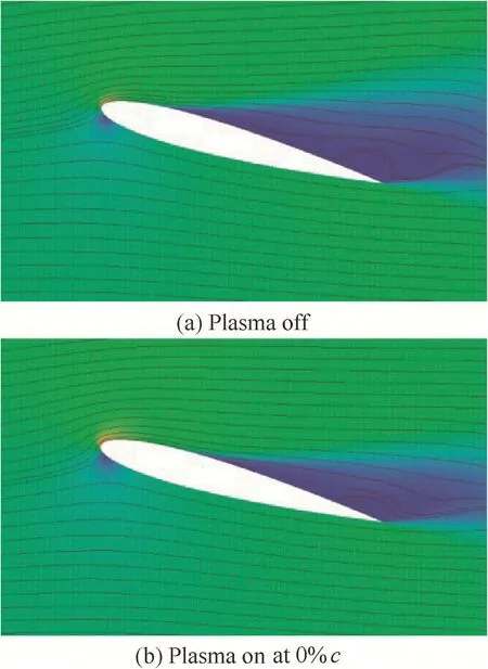
Fig.8 Streamlines and velocity contours at AOA of 15.21°in down-stroke motion.
4.2.Active flow control
4.2.1.Effect of plasma pulsefrequency
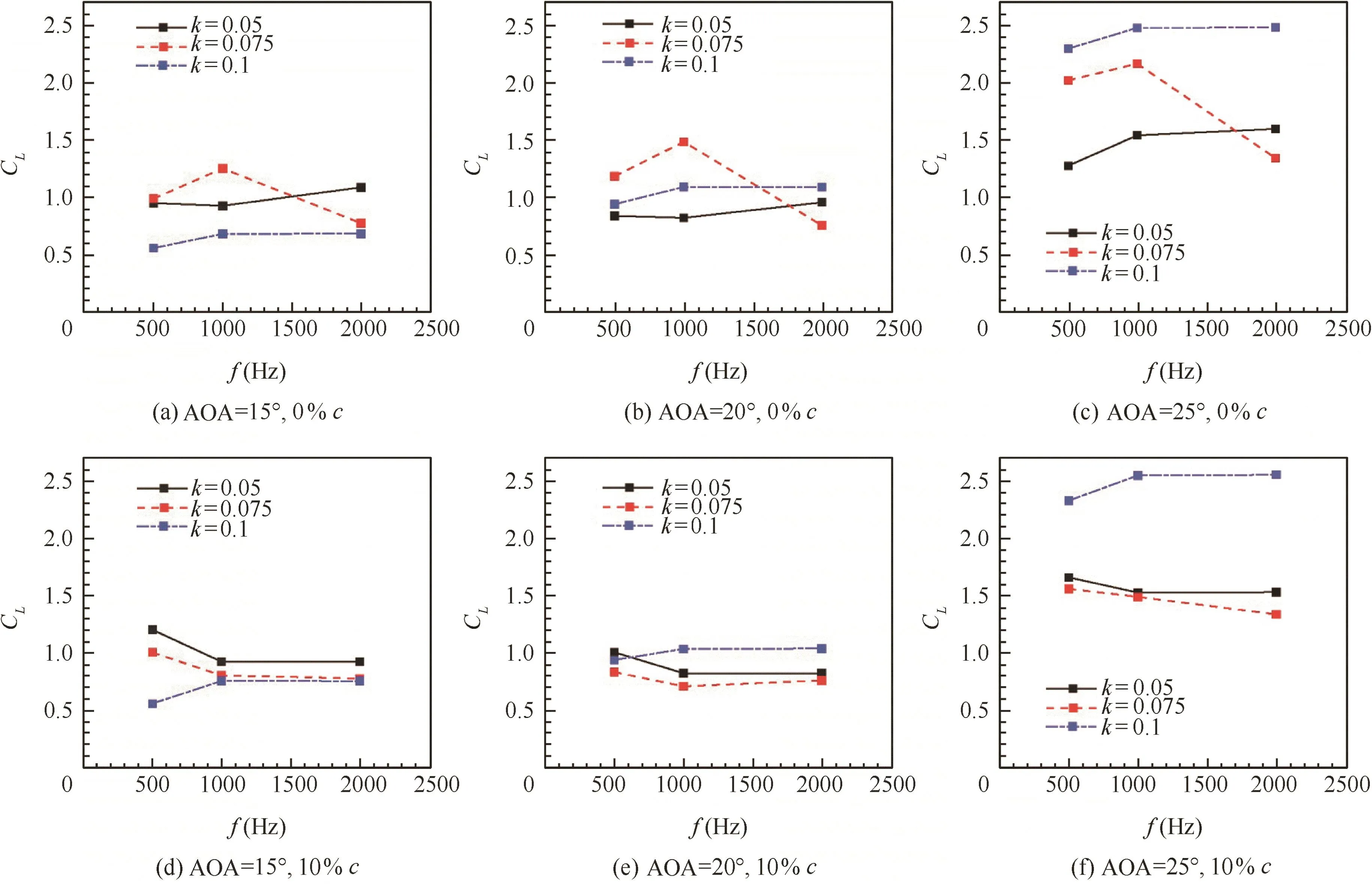
Fig.9 Lift coefficients in down-stroke motion at various plasma pulse frequencies and reduced frequencies.
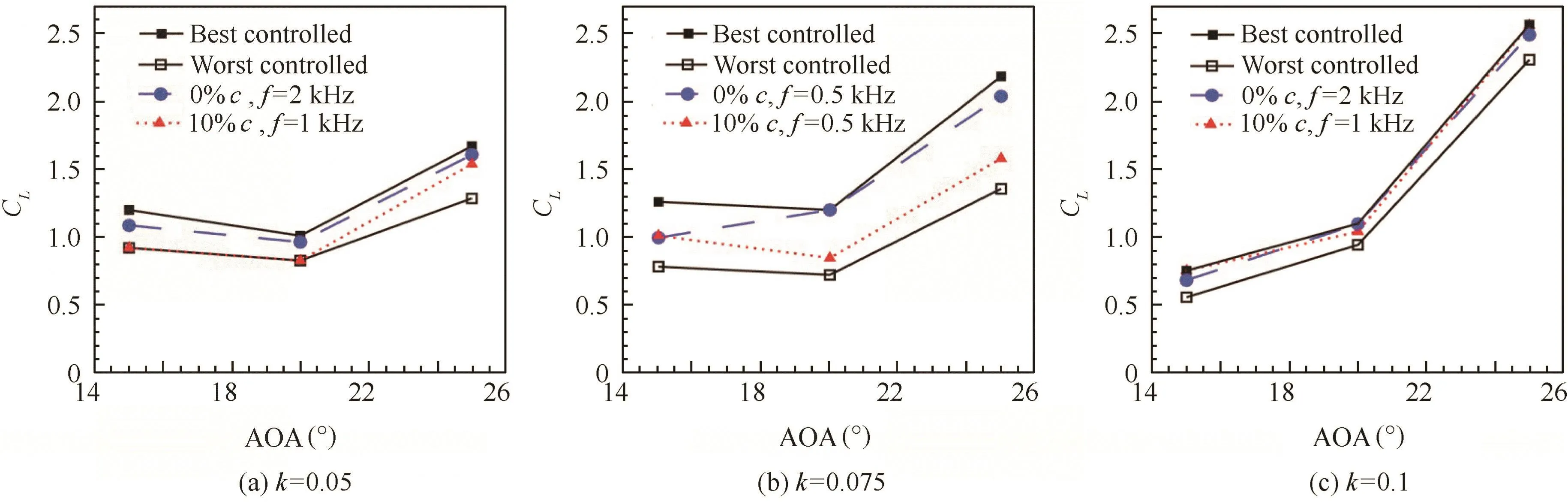
Fig.10 Lift coefficients in down-stroke motion under various combinations of control parameters at each fixed reduced frequency.
Dynamic situation as in oscillating airfoil inherently requires an activeflow control as proven by Fig.6 where the plasma actuator does not play a role in up-stroke motion and aerodynamic characteristics change as the location of the plasma actuator changes in down-stroke motion.The effectiveness of plasma actuator can be tuned by various parameters such as plasma frequencies,actuation magnitude and actuator locations.For static airfoil,the effectiveness is known to be optimum when Strouhal number is equal to unity.27,32Since a reduced frequency(k)is one of key parameters in oscillating airfoil,corresponding time-dependent parameter,plasma pulse frequency(f)should also be adjusted in response to a dynamic change in the reduced frequency.The previous results presented above were taken from the cases where the reduced frequency and the plasma pulse frequency are fixed at k=0.1 and f=2 kHz,respectively.Fig.9 provides the effect of plasma pulse frequency at various reduced frequencies of k=0.05,0.075 and 0.1 at specific AOAs of 15°,20°and 25°in down-stroke motion.The top row corresponds to the plasma actuator at 0%c and the bottom row corresponds to the plasma actuator at 10%c.When the reduced frequency is low at k=0.05,high frequency plasma pulsed at 2 kHz produces bigger actuation effect than at lower frequencies when the plasma actuator is placed at 0%c,but 500 Hz pulsing produces bigger effect with the plasma actuator at 10%c.When the reduced frequency is intermediate at k=0.075,there exists a maximum-lift point at plasma pulse frequency of 1 kHz when the plasma actuator is located at 0%c,but the maximum points are not observed with the plasma actuator at 10%c.When the reduced frequency is high at k=0.1,the actuation effect at pulse frequencies of 1 kHz and 2 kHz produces similar CLfor all AOAs and actuator locations.A noticeable decrease in CLis observed with k=0.1 as the AOA decreases regardless of plasma frequencies and actuator locations.The result shown in Fig.9 infers that in fact when the reduced frequency or AOA changes in time,corresponding flow control must be operated in an active manner.As the AOA decreases(i.e.,in down-stroke motion),plasma pulse frequency and actuator location should be carefully selected so that aerodynamic performance remains in the best condition.Fig.10 shows some examples of the selection of control parameters(plasma pulse frequency and actuator location)when the AOA decreases at each fixed reduced frequency based on the values presented in Fig.9.The best-controlled line connects the highest CLs from Fig.9 at each AOA and the worst-controlled line connects the lowest CLs that could have been produced by bad selection of plasma pulse frequency and actuator location.Dotted lines and dashed lines correspond to some cases in Fig.9 with the fixed operating conditions.The result shown in Fig.10 confirms a nominal increase in CLup to 70%by a simple combination of control parameters in an active manner.Note that these results do not include the transient or hysteresis effect of changing plasma pulse frequency or actuator location as AOA changes.
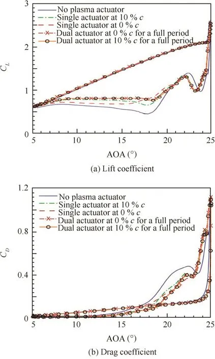
Fig.11 Lift and drag coefficients with both plasma actuators at 0%c and 10%c being addressed.
4.2.2.Effect of dual plasma actuators at both 0%c and 10%c It is observed in the previous results that the flow actuation is strongly dependent on actuator locations.It is also observed that the plasma actuator does not play a role in up-stroke motion.Now two plasma actuators located at both 0%c and 10%c are addressed within one cycle.Fig.11 presents lift and drag coefficients with various flow control sequences compared with no actuation case.Solid line corresponds to the case without plasma actuator.Dashed and dot-dashed lines correspond to the cases with single plasma actuator where the plasma actuator is kept turned on for the entire cycle.Dot-dashed line with a cross symbol corresponds to the case with dual plasma actuators being turned on for the entire cycle.For the line with a circular symbol,the plasma actuator at 0%c is turned on in a full up-stroke motion and at high AOAs(from 25°to 16.5°)in down-stroke motion while the plasma actuator at 10%c is turned on only in a full down stroke motion.Active flow control in dynamic situation must consider the hysteresis effect because the effect of ten occurs in a delayed time.It is found that the actuation effect is observed after short time delay of about a few micro seconds after the actuator is addressed.For this reason,the plasma actuator at 0%c which showed a better performance at high AOAs is turned on in full up-stroke motion much earlier than a dynamic stall occurs.It is found from Fig.11 that the dual plasma actuator cases exhibit a reduced oscillation in downstroke motion with improved lift and drag characteristics overall.Sequentially addressed plasma flow actuator(line with a cross symbol)produces almost the same characteristics with dot-dashed line with a cross symbol with less power consumption.More precise control of the addressing time is expected to provide an improved flow actuation performance.The result in Fig.11 clearly tells that theflow actuation is better to be conducted in an active manner in dynamic situation.Optimization study is needed to provide the best control sequence for plasma frequencies and actuator locations for dynamically varying reduced frequencies and AOAs.
5.Conclusions
In this paper,we investigated the effect of plasma flow actuation on the aerodynamic characteristics of a flow over an oscillating airfoil with various values of plasma pulse frequency,reduced frequency and actuator location.The simulation results show that the presence of plasma actuator changes the propagation of LEV and the formation of the second and the third vortex generated near the leading edge.As a result,the oscillatory behavior of the surface pressure in down-stroke motion was delayed and weakened so that the wake region was reduced.It turned out that the plasma actuator does not modify theflow in up-stroke motion except at high AOAs near the stall angle.It was found that depending on the actuator location,the effect of flow actuation was different in down-stroke motion.Also the plasma pulse frequency produced different actuation performance with various reduced frequencies.Bigger actuation effect can be expected by increasing the number of plasma actuators on the airfoil surface.Dual plasma actuators located at both 0%c and 10%c proved an improved flow characteristic.But the efficiency must also be considered in order to avoid redundant power consumption.Result from the case with dual plasma actuators confirms that a careful choice of control sequence could be more energy efficient with a similar flow actuation capability.Owing to the dynamic change of flow conditions in oscillating airfoil,an active flow control must be considered to provide an optimum flow control authority with a minimum power budget.Example with active flow control has shown about 70%difference in a lift coefficient.For this purpose,plasma flow actuator can be a good candidate owing to a simple structure on the airfoil surface and a high bandwidth actuation.Optimization study with multiple plasma actuators may be expected to result in much improved flow actuation effect in an oscillating airfoil problem.
Acknowledgements
This research was supported by the Basic Science Research Program through the National Research Foundation of Korea(NRF)funded by the Ministry of Science,ICTamp;Future Planning(No.2013R1A1A1012693),and was conducted at High-Speed Vehicle Research Center of KAIST with the support of Defense Acquisition Program Administration(DAPA)and Agency for Defense Development(ADD).
1.Le PA,Lienard C,Bailly J.Active flow control for helicopters.J Aerospacelab 2013;4(6):1–11.
2.Aiken EW,Ormiston RA,Young LA.Future directions in rotorcraft technology at Ames Research Center.Proceedings of the American helicopter society’s 56th annual forum;2000 May 2–4;Virginia Beach(VA).Fairfax(VA):American Helicopter Society;2000.
3.Gerontakos P.An experimental investigation of flow over an oscillating airfoil[dissertation].Montreal:McGill University;2004.
4.Koochesfahanni MM.Vortical patterns in the wake of an oscillating airfoil.AIAA J 1989;27(9):1200–5.
5.Wang S,Ingham DB,Ma L,Pourkashanian M,Tao Z.Numerical investigations on dynamic stall of low Reynolds number flow around oscillating airfoils.Comput Fluids 2010;39(9):1529–41.
6.McAlister KW,Pucci SL,McCroskey WJ,Carr LW.An experimental study of dynamic stall on advanced airfoil sections.Volume 2:Pressure and force data.Mof fett Field(CA):Ames Research Center,U.S.Army Aeromechanics Laboratory(AVRACOM);1982.Report No.:NASA Technical Memorandum 84245.
7.Godard G,Stanislas M.Control of a decelerating boundary layer.Part 1:Optimization of passive vortex generators.Aerosp Sci Technol 2006;10(3):181–91.
8.Douglas GB,Ralph JV.Experiments with three-dimensional passive flow control devices on low-pressure turbine airfoilds.J Turbomach 2004;128(2):251–60.
9.Lin JC.Review of research on low-profile vortex generators to control boundary-layer separation.Prog Aerosp Sci 2002;38(4–5):389–420.
10.Shun S,Ahmed NA.Wind turbine performance improvement using activeflow control techniques.Procedia Eng 2012;49:83–91.
11.Geissler W,Trenker M,Sobieczky H.Active dynamic flow control studies on rotor blades.The RTO AVT symposium on ‘active control technology for enhanced performance operational capabilities of military aircraft,land vehicles and sea vehicle”conference;2000 May 8–11;Branchweig.Brussels:NATO;2000.
12.Post ML,Corke TC.Separation control using plasma actuators:dynamic stall vortex control on oscillating airfoil.AIAA J 2006;44(12):3125–35.
13.Corke TC,Bowles PO,He C,Matlis EH.Sensing and control of flow separation using plasma actuators.Philos T R Soc A 2011;369:1459–75.
14.Martinat G,Hoarau Y,Braza M,Vos J,Harran G.Numerical simulation of the dynamic stall of a NACA0012 airfoil using DES and advanced OES/URANS modelling.Note on Numerical Fluid Mechanics and Multidisciplinary Design 2008;97:271–8.
15.Martinat G,Braza M,Hoarau Y,Vos J,Harran G.Turbulence modelling of the flow past a pitching NACA0012 airfoil at 105 and 106 Reynolds numbers.J Fluid Struct 2008;24(8):1294–303.
16.Carta FO.Unsteady normal force on an airfoil in a periodically stalled inlet flow.J Aircraft 1967;4(5):416–21.
17.Ericsson LE.Comment on unsteady airfoil stall.J Aircraft 1967;4(5):478–80.
18.Srinivasan GR,Ekaterinaris JA,McCrosskey WJ.Evaluation of turbulent model of unsteady flow over an oscillating airfoil.Comput Fluids 1995;24(7):833–61.
19.Akbari MH,Price SJ.Simulation of dynamic stall for a NACA0012 airfoil using a vortex method.J Fluid Struct 2003;17(6):855–74.
20.Correa AFM,Sales TP,Rade DA,Souza FJ.Study of the flow over an oscillating NACA0012 airfoil.National congress of mechanical engineering(CONEM 2014);Aug 10–15;Uberlandia,Brazil;2014.
21.Ekaterinaris JA,Platzer MF.Computational predict of airfoil dynamic stall.Prog Aerosp Sci 1998;33(11–12):759–846.
22.Spalart PR,Allmaras SR.A one-equation turbulence model for aerodynamic flows.Rech Aerospatiale 1994;1:5–21.
23.Alexis L,Zha GC.Numerical simulation of pitching airfoil performance enhancement using co- flow jet flow control.Proceedings of the 31st AIAA applied aerodynamics conference;2013 Jun 24;San Diego(CA).Reston:AIAA;2013.
24.Abbotte IH,Doenhof f AE.Theory of wing sections.New York:Courier Dover;1959.p.462–3.
25.Shin J,Rahman MS.Characteristics of sheath-driven tangential flow produced by a low current surface glow discharge plasma actuator.Jpn J Appl Phys 2014;53(8):086201.
26.Gretton GI.The hydrodynamic analysis of a vertical axis tidal current turbine[dissertation].Edinburgh:The University of Edinburgh;2009.
27.Tuncer IC,Wu JC,Wang C.Theoretical and numerical studies of oscillating airfoils.AIAA J 1990;28(9):1615–24.
28.Marongiu C.Aerodynamics of the oscillating airfoils[dissertation].Naples:The University of Naples;2011.
29.Sohail MA,Ullah R.CFD of oscillating airfoil pitch cycle by using PISO algorithm.Int Sci Ind 2011;5(12):1282–6.
30.Barakos GN,Drikakis D.Computational study of unsteady flows around oscillating and ramping aerof oils.Int J Numer Meth Fluid 2003;42(2):163–86.
31.Liggett ND.Numerical investigation of static and dynamic stall of single and flapped airfoils[dissertation].Atlanta:Georgia Institute of Technology;2012.
32.Greenblatt D,Wygnanski IJ.The control of separation by period excitation.Prog Aerosp Sci 2000;36(7):487–545.
Minh Khang Phan received the B.S.degree from Hochiminh City University of Technology,Vietnam in 2013,and the M.S.degreefrom University of Ulsan,South Korea in 2015.He is currently a research associate in aerospace engineering in University of Ulsan,South Korea.His current research interest is computational simulation of unsteady turbulent flow and plasma synthetic jet.
Jichul Shin received the B.S.degree from Inha University,South Korea in 1998,and the M.S.and Ph.D.degrees from University of Texas at Austin,USA in 2004 and 2007,respectively.He is currently an associate prof essor in aerospace engineering in University of Ulsan,South Korea.His current research interests are aerodynamic plasma flow control and micro plasma thrusters.
30 July 2015;revised 15 December 2015;accepted 11 April 2016
Available online 22 June 2016
Dynamic stall;
Flow control;
Numerical simulation;
Oscillating airfoil;
Plasma actuator
©2016 Chinese Society of Aeronautics and Astronautics.Production and hosting by Elsevier Ltd.Thisisan open access article under the CC BY-NC-ND license(http://creativecommons.org/licenses/by-nc-nd/4.0/).
*Corresponding author.Tel.:+82 522592136.
E-mail address:jshin@ulsan.ac.kr(J.Shin).
Peer review under responsibility of Editorial Committee of CJA.
Production and hosting by Elsevier
http://dx.doi.org/10.1016/j.cja.2016.06.004
1000-9361©2016 Chinese Society of Aeronautics and Astronautics.Production and hosting by Elsevier Ltd.
This is an open access article under the CC BY-NC-ND license(http://creativecommons.org/licenses/by-nc-nd/4.0/).
杂志排行

CHINESE JOURNAL OF AERONAUTICS的其它文章
- Numerical simulation of aerodynamic interaction for a tilt rotor aircraft in helicopter mode
- Investigation of MHD power generation with supersonic non-equilibrium RF discharge
- Experimental study on ceramic membrane technology for onboard oxygen generation
- Transition study of 3D aerodynamic configures using improved transport equations modeling
- Characterization of component interactions in two-stage axial turbine
- Numerical study of aerodynamic characteristics of FSW aircraft with different wing positions under supersonic condition