Robust fault-tolerant control for wing flutter under actuator failure
2016-11-24GaoMingzhouCaiGuoping
Gao Mingzhou,Cai Guoping
Department of Engineering Mechanics,State Key Laboratory of Ocean Engineering,Shanghai Jiaotong University,Shanghai 200240,China
Robust fault-tolerant control for wing flutter under actuator failure
Gao Mingzhou,Cai Guoping*
Department of Engineering Mechanics,State Key Laboratory of Ocean Engineering,Shanghai Jiaotong University,Shanghai 200240,China
Many control laws,such as optimal controller and classical controller,have seen their applications to suppressing the aeroelastic vibrations of the aeroelastic system.However,those control laws may not work effectively if the aeroelastic system involves actuator faults.In the current study for wing flutter of reentry vehicle,the effect of actuator faults on wing flutter system is rarely considered and few of the fault-tolerant control problems are taken into account.In this paper,we use the radial basis function neural network and the finite-time H∞adaptive fault-tolerant control technique to deal with the flutter problem of wings,which is affected by actuator faults,actuator saturation,parameter uncertainties and external disturbances.The theory of this article includes the modeling of wing flutter and fault-tolerant controller design.The stability of the finite-time adaptive fault-tolerant controller is theoretically proved.Simulation results indicate that the designed fault-tolerant flutter controller can effectively deal with the faults in the flutter system and can promptly suppress the wing flutter as well.
1.Introduction
With the rapid development of aerospace technology,modern aircraft per form their characteristics such as high velocity,lightweight structures,flexible and low damping,which makes the aeroelasticity phenomenon more and more prominent.Flutter is one of such problems.Flutter instability may decrease aircraft performance or even lead to the catastrophic failure of the structure.1The traditional passive techniques are usually inefficient(because they add weight to the structure),and they do not always succeed.In order to overcome the inadequacy of passive techniques,the activeflutter suppression techniques were developed in early 1970s.In activeflutter suppression,we carry it out by utilizing multiple steerable control surfaces laid out on the surface of the wing.
The technique of activeflutter suppression has drawn much attention over the past decade.2–6For example,Yu et al.2designed a μ controller to suppress airfoil flutter,and wind tunnel experiments were carried out to verify the effectiveness of the designed controllers.Prime et al.3synthesized a statefeedback controller using linear matrix inequalities(LMIs)to control the vibration of an improved three-degree-of -freedom aeroelastic model and this controller could effectively suppress limit-cycle oscillations over a range of airspeeds.Wang et al.4,5considered a class of aeroelastic systems with an unmodeled nonlinearity and external disturbance and proposed a fullstate feed forward/feedback controller with a high-gain observer;they also designed a continuous robust controller to suppress the aeroelastic vibrations of a nonlinear wingsection model.Zhang et al.6designed a partial statefeedback continuous adaptive controller in order to suppress the aeroelastic vibrations of the wing section model.
Although a number of flutter controller design approaches,2–6most of the researches assume that there exists no actuator fault or failure during the entireflutter suppression.This assumption is rarely satisfied in practice because some catastrophic faults may occur due to the malfunction of actuators.As a result,if the flutter controller is designed without any fault tolerance capability,an abrupt occurrence of an actuator fault could ultimately fail the flutter control.There fore,we must give priority to considering the faults of actuators and sensors in the design of the flutter controller.There fore,the fault-tolerant control(FTC)7should be taken into consideration for the flutter control.In general,FTC methods are classified into two types:passivefault-tolerant control(PFTC)and activefault-tolerant control(AFTC)schemes.7The PFTC designed by limited faults and fixed controller will not be able to guarantee the performance of the system.8–10Correspondingly,active method11–13may provide more powerful fault-tolerant capability for compensating for faults of the systems in terms of reconfiguring control strategies online or switching to a more suitable control law based on the fault in formation.There fore,in this paper,the investigation of an activefault-tolerant controller for a flutter control system with the occurrence of unexpected faults or failures.It is worth mentioning that the above results2–6are derived from the assumption that the actuators are able to provide any requested outputs.However,in almost every physical application,the actuator has bounds on its input.There fore,the phenomenon of actuator saturation has to be considered when the controller is designed in practical industrial process control field.In addition,the flutter will destroy the vehicle in a short time,we must control the flutter within a certain range in a finite time.However,to the best of our knowledge,the studies on finite-time adaptive fault-tolerant control of wing flutter are very limited in the published literature.
In order to reveal the negative effect of the conventional control on the stability of aeroelastic system and considering the in fluence of faults,time-varying parameter uncertainties and external disturbances,this paper focuses on the design of finite-time H∞adaptive fault-tolerant controller for flutter of wing.A 2D cubic structure nonlinearity wing system is adopted as structure model.The actuator fault is considered in the controller design.This paper is organized as follows.The dynamic equation of wing flutter and the control problem of flutter system with faults are established in Section 2.Section 3 presents a finite-time adaptive fault-tolerant flutter controller based on observer.Numerical simulations are given in Section 4.Section 5 briefs the conclusions of the research.
2.Flutter model of 2D wing and fault-tolerant control problem
In this section,we briefly recall the mathematical model for the flutter of a reentry vehicle with actuators fault-free.Based on this nominal flutter system,the state equation with actuator faults and saturation,parameter uncertainties and external disturbances are established.
2.1.Wing flutter model under actuators fault-free
In this section,flutter problem for a 2D wing including cubic hard spring nonlinearity is analyzed.As shown in Fig.1,a two degree-of -freedom(2-DOF)wing system model is considered herein.The plunge deflection is denoted by h,positive in the downward direction;θ is the pitch angle about the elastic axis,positive nose up;V denotes the air speed;the chord length is c;Q,p and C are the aerodynamic center,elastic axis and center of mass,respectively;the distance from the leading edge to the elastic axis is xp,and that from the leading edge to the mass center is xC; δLEoutand δLEin(or δREoutand δREin)are the control surface angles.
From Fig.1,the velocity of mass center of wing can be expressed as

The kinetic energy,potential energy and dissipation of the system can be given by
where IC,mW,me,Kh,Kθ,Chand Cθare the moment of inertia about center of mass,wing mass,wing extra-mass,stiffness coefficient in plunge,torsion stiffness coefficient,damping coefficient in plunge and torsion damping coefficient,respectively.
For supersonic and hypersonic flow,the piston theory is widely used to calculate the aerodynamics acting on a lifting surface.14Applying the piston theory,the aerodynamic force and moment acting on the wing can be obtained as


Fig.1 2D wing model with control surface.
The aerodynamic lift and moment caused by control surface can be expressed as

where aCis the coefficients of lift force,bCthe ratio of the pitching moment to the deflection angle,and sβthe span of control surface.
The moment caused by the cubic hard spring nonlinearity of the wing can be written as15

where en1is the nonlinear stiffness coefficient.
Without considering structural damping,the aeroelastic equation of the two-dimensional wing system can be deduced using the Lagrangian method and written into matrix form,we have

where q(t)=[h(t),θ(t)]Tis the generalized displacement vector;~A,~B,~C and~D are the inertia,aerodynamic damping,aerodynamic stiffness and structural stiffness matrices respectively;u(t)=[δLEout,δLEin]Tis the control input.The expressions of parameters in Eq.(6)are


Eq.(6)can befurther changed to be

The parameters in the matrices A and B are determined based on the computing results for the most serious moment of reentry flight of the vehicle given in Ref.16.In Ref.16,the reentry will reach its maximum velocity of 1406 m/s at the moment 699.19 s;the altitude,longitude,latitude and atmospheric density of the reentry vehicle at this serious moment can be determined to be 21.87 km,3907.11 km,-66.05 km and 0.0644 kg/m3,respectively.
2.2.Wing flutter model under actuator failures
Note that the dynamic equation of flutter in Eq.(7)assumes that all of the actuators arefault-free,and it is called the nominal system.For an active flutter control system,it is difficult to ensure the actuator in the ideal working condition.They are likely to have some problems,such as loss of effectiveness,float or saturation.For the hypersonic reentry vehicle,the aircraft will face hostile aerodynamic environment in the reentry process,such as high temperature,high pressure.The actuator may havefaults,such as loss of effectiveness and float,which are likely to cause catastrophic accidents of the reentry vehicle.There fore,fault tolerance capability should be considered in lf utter controller design.

Fig.2 Time responses of wing states and observer errors in case of fault.
In this section,we consider two types of actuator fault simultaneously,namely the float fault(actuators generate additional torque under zero control command caused by voltage or current intermittent fault)and the loss of effectiveness of the actuators as well as actuator saturation,parameter uncertainties and external disturbances.Hence,the flutter dynamic model given by Eq.(7)can be rewritten as
where ΔA represents the parameter uncertainties of wing flutter system, v(t) the actual actuator control vector,ρ =diag(ρ1,ρ2)the effectiveness factor matrix for the reentry vehicle actuators with 0 < ρi≤ 1(i=1,2);the case when ρi=1 means that the ith actuator works normally,and 0< ρi< 1 denotes the case in which the ith actuator partially loses its effectiveness.us(t)= [us1,us2]T∈ R2×1corresponds to the ith actuator float fault of reentry vehicle;f(t,x)is a nonlinear term;w(t)represents the external disturbances;and y(t)is the measured output.The parameters B1and c1are known matrices with appropriate dimensions.ΔA is assumed to satisfy thefollowing matching condition of Eq.(9).

Fig.3 Commanded control in case of fault.

where ‖·‖represents Euclidean norm of vectors or matrices;N(t)is an unknown matrix with‖N‖≤ l*and l*is an unknown constant.
Remark 1.The assumption ΔA=BN(t)in this paper is made for the convenience of design is the controller(Eq.(20)).Through the assumption ΔA=BN(t),we altered the uncertainties of ΔA into the uncertainties of N(t).In our paper,we made compensation for N(t)by the adaptive law^k5(Eq.(23)).v is the actual actuator control vector defined as

where vmaxand δu(x)are the actuator saturation level and auxiliary variable;u(t)is the control signal to be designed.
In nonlinear control problem,the radial basis function(RBF)network is usually used as a tool for modeling nonlinear system because of its good capabilities in function approximation.In this paper,the unknown δu(x)is approximated by the RBF network17
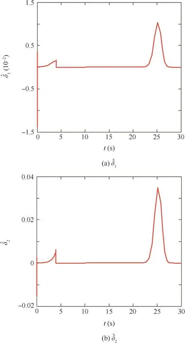
Fig.4 Output of neural networks.

Herein,x is the input of neural networks and δu(x)the output of neural networks;the subscript N means the Nth input of neural networks;hN(x)is the Gaussian function;h(x)is the output of Gaussian function;cNand bNare the centre vector and width;W*is the idealweight matrix.Definedenotes the estimate of δu(x), andthe estimate of W*,εu(x)the approximation error,and Dx∈R4×1a sufficiently large compact set.
3.Observer-based finite-time H∞adaptive fault-tolerant flutter controller design
In this section,an active fault-tolerant flutter controller design for reentry vehicle is presented,including the design of the observer and the design of the fault-tolerant flutter controller.The observer design is first presented to achieve precise estimated flutter states without states measurement.A faulttolerant flutter controller is then designed using the flutter states in formation from the observer to per form the flutter stabilization control.
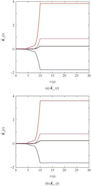
Fig.5 Adaptive parameters of ^K11(t)and^K12(t).
3.1.Design of observer
In this section,an observer is designed,which can provide the in formation of flutter states.These in formation is sent to the controller to obtain the control law,which is sent back to the actuator.
Considering the form of the model Eq.(8),the following observer is designed:

Table 1 Structural parameters of 2D wing.

Fig.6 Adaptive parameters of

By using the definition e(t)=x(t)-the dynamics of the error e(t),between the actual state x(t)and its estimate values^x(t),can be obtained from Eqs.(8)and(12)as

Theorem 1.If there exists a positive-definite matrixand considering the estimation error Eq.(13),we suppose that the observer gains are chosen as
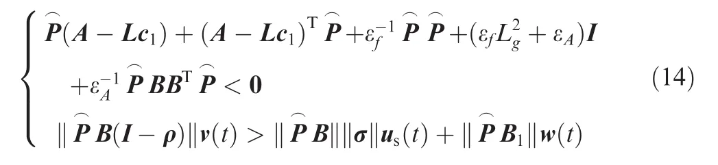
Then the estimation error dynamics system e(t)is stable.Proof .Select the following Lyapunov functionDifferentiating the above Lyapunov function yields

Let NT(t)N(t)≤ I,if there exist scalars εf≥ 0 and εA≥ 0,f(t,x)-f(t,^x) satisfies the Lipschitz condition> 0,note thefact that for any positive constant¯c>0,

According to Theorem 1,Eq.(18)can be written as

then the error dynamics system Eq.(13)is stable.Thereby the proof is completed.□
3.2.Finite-timefault-tolerant flutter controller design
In this section,a novel finite-timefault-tolerant flutter control algorithm is investigated to suppress the wing flutter based on the observer Eq.(12).
Considering Eqs.(8)and(11),the adaptiveflutter control law is designed as

Below we give the expressions ofand then utilize the Lyapunov method to prove that the flutter controller given by Eq.(20)can guarantee the stability of the system.The adaptive gain^K1i(t)is chosen as

where α1, β1and η are given positive constants;^k4and^k5are updated by thefollowing adaptive equations of Eq.(23).

where r1and r2are given positive constants.^W is given as
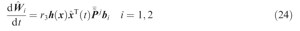
where r3is a given positive constant.

where k4and k5are positive constants for eliminating the effects of float, external disturbances and parameter uncertainties.
Substituting Eqs.(10)and(20)into Eq.(8),the closed-loop flutter system can be written as)

Assumption 1.For any given positive number ds,dw,dδand the actual working time Tf,the float fault us(t),nonlinear vector f(t,x),external disturbances w(t)and ¯δu(x)are time-varying and satisfy

Remark 2.The actual output torque generated is bounded due to practical physical limitations of the actuators,and thus,the float fault us(t)and the auxiliary variable(δu(x)=v(t)-u(t))are also bounded.In addition,the external disturbances w(t),in Eq.(8)include center of mass migration,moment of inertia error,gravitational perturbation,atmospheric density deviation,and are also bounded.Assumption 1 is,there fore,reasonable for flutter system.
Definition 118.For given positive constants c1,ds,df,dw,Tfand a symmetric matrix R>0,the resulting closed-loop flutter system Eq.(26)is said to be robustly finite-time bounded(FTB)with respect to(c1,c2,Tf,R,ds,df,dw),if there exists a constant c2(c2>c1),such that

Definition 219.If there exists feedback controller in form Eq.(20),such that the resulting closed-loop flutter system Eq.(26)is FTB with respect to(c1,c2,Tf,R,ds,dw,dδ)under the assumed zero initial condition,the flutter system output satisfies the following inequality for Tf>0 and for all admissible w(t)which satisfy Assumption 1.
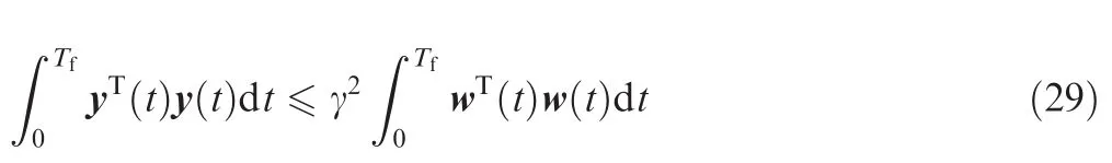
where γ is a constant.Then the flutter control law Eq.(20)is called the robust finite-time H∞flutter controller of the nonlinear flutter systems Eq.(26).

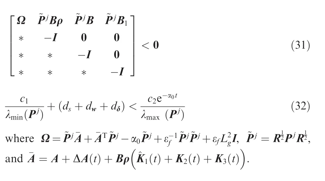
Theorem 2.For given positive constants α0,c1,Tf,ds,dw,dδand a symmetric matrix R>0,the closed-loop flutter control system Eq.(26)is FTB with respect to(c1,c2,Tf,R,ds,dw,dδ),if there exist positive constant c2and symmetric positive-definite matrix~P,such that
Proof .For the closed-loop flutter system Eq.(26),wefirst define a Lyapunov functional candidate as

Using Eq.(17),Eq.(33)can be written as
Define the following function
The condition inequality(31)implies J1<0.Multiplying the above inequality by e-α0t,we derive
On the other hand,the following condition holds:
Condition Eq.(32)implies that for ∀t∈ [0,Tf],xT(t)Rx(t)<c2.According to Definition 1,this completes the proof .□
Theorem 3.For given positive constants α0,c1,Tf,ds,dw,dδ,μ,α1,β1,k4,k5and a symmetric matrix R > 0,the closed-loop flutter control system Eq.(26)is FTB with respect to(c1,c2,Tf,R,ds,dw,dδ)and satis fies the Eq.(29) for all admissible w(t),if there exist positive constants c2,γf> γn,η,εf,symmetric positive-definite matrixP~-jfor any ρ and any appropriately dimensioned matrices Z,Jjand L,which satisfy


Proof .Select the same Lyapunov function candidate as Theorem 2 and define the following function.
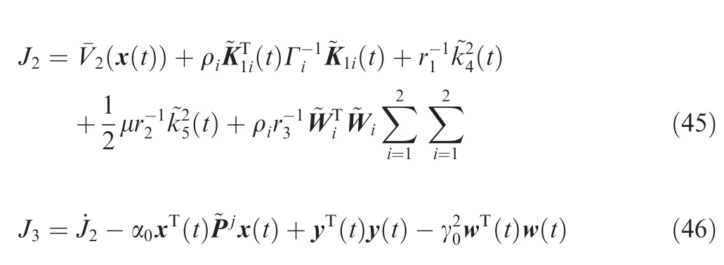
Then,according to Eqs.(9),(11),(26),(22)and(25),J3can be written as
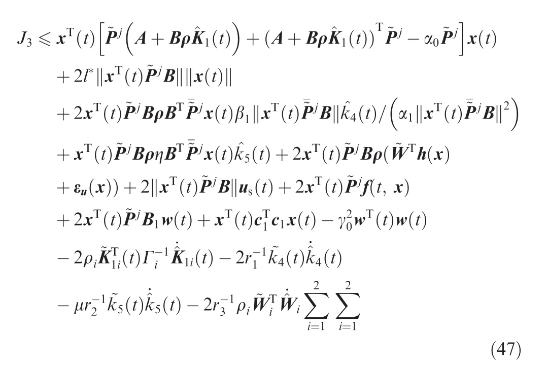
Note the fact that for any positive constant γ0> 0,

By Eqs.(42)and(43),we can obtain
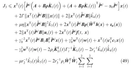
Using Eqs.(16)and(17),we have

Using Eqs.(25)and(44),Eq.(51)becomes


Using Eq.(30),Eq.(53)can be written as

Pre-and post-multiplying the inequality(54)by blockdiagonal matrix diag(~P-j,I,...,I),Eq.(54)can befurther changed to be

where Ω2=.
For any positive constant Χ > 0,Eq.(55)is equivalent to

where Λ = [I, 0, Χ-1cT1, 0].Then,applying Eq.(30),Eq.(56)can be written as

Pre-and post-multiplying both sides of Eq.(57)by diag(ZT,I,...,I),Eq.(57)can befurther changed to be
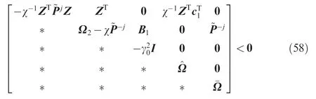
Due to ZT~PjZ≥Z+ZT-~P-j,Eq.(58)can be written as

where Ω3= Χ-1(~P-j-Z-ZT).Let K1=LZ-1,from Eq.(59)we have
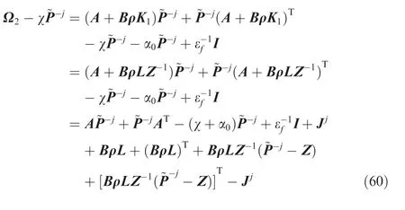

Then,applying Eq.(30),Eq.(60)can be written as
where Ω4=A~P-j+~P-jAT-(Χ + α0)~P-j+ ε-1fI+Jj+BρL+(BρL)T
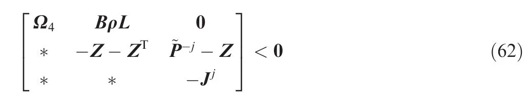
From Eq.(62),Eq.(59)can be written as

From Eq.(63),Eq.(52)can be written as
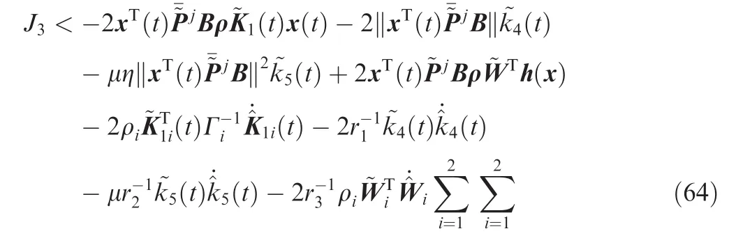
From Eqs.(21),(23)and(24),Eq.(64)can be written as

which implies that the flutter system is ultimately uniformly bounded,and the flutter state x(t)converges to zero.□
Remark 3.Assume that LMIs(40)and Eqs.(41)–(44)are satisfied,control gain K2(t),K3(t),adaptive update laws^K1i(t),^k4(t),^k5(t)and^W are given by Eqs.(22),(21),(23)and(24)then the closed-loop flutter system Eq.(26)is stable,then γnand γfare minimized if the following optimization problem is solvable

where αnand αfare weighting coefficients.
4.Numerical simulations
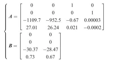
In this section,numerical example is provided to illustrate the validity of our proposed approaches.The flutter of twodimensional nonlinear wing is used as numerical example.Table 1 shows the structural parameters of 2D wing.The matrices A and B in Eq.(7)are given by
In the simulations,the parameters bN,η,Γi,r1,r2and r3in Eqs.(11),(22),(21),(23)and(24)are chosen as
bN=5, η=100,Γi=0.45, r1=0.25, r2=0.25, r3=4.5
The parameters N(t),cNand the initial values of the state x(t)in Eqs.(9),(11)and(7)are

The reentry vehicle is assumed to experience the following faulty case during its operation:be fore 4 s,the system operates in normal case,that is,all of the two actuators are normal.Between the 4th and the 10th second,thefirst actuator is float at us(t)=30+30 sin(0.1t)+20 cos(0.5t)and the second actuator is loss of effectiveness,that is,ρ2=1-0.05t until loss effectiveness of 50%.After the 10th second,the second actuator has float fault and other actuator is loss of effectiveness,that is,ρ1=1-0.01t until loss effectiveness of 70%.The perturbations w(t)= [-10sin(0.1t),15]Tenter the systems at the beginning(t≥0 s).
Using algorithm with αn=5,αf=1,we obtain H∞performances of the closed-loop flutter system as 0.3923(normal)and 1.3553(fault).Fig.2 shows that the state variable x(t)of wing flutter and observer error e in case of fault.Fig.3 illustrates the control signals’variations under different faults,which is,the parameter u(t)in Eq.(7).In the simulation of this paper,we assume that vehicles’two actuators from the 4th second to the 10th second have some faults,while external disturbances exist all the time.From Fig.2 we can see that in the fault situations mentioned above,by using the controller(as shown in Fig.3)which we have put forward in this article,the flutter can be controlled within 1 s,which verifies the reliability and the robustness of the control method proposed in this article.Fig.4 displays the output of neural networks(x).From Fig.4,we can see that the neural networks(x)will change parameters to adjust the controller when the actuator is under saturation situation.
Fig.5 shows the variation of control gain(t)in different situations,which(t)ensures the stable of the flutter system.We also know that)varies with the flutter state in Eq.(21).The faults in the actuator might cause changes in the flutter state(as shown in Fig.2).From Fig.5,control gain(t)will change parameters to adjust the controller when faults occur,so that the actuator of the vehicle would receive effective compensation and return to stable state.From Fig.5,when wing flutter is back to stable,the control law(t)will not change any more.
In order to effectively compensate the actuator float fault and uncertainties of flutter dynamic model mentioned above and ensure the stability of the flutter system,we design the control lawandin this article.From Eq.(23),we can find thatandchange with the flutter state variation.Under the circumstances of the faults of actuator and parameters uncertainty,the state of flutter system may have corresponding changes.From Fig.6,we can see that the parameters of control gain^k4and^k5may justify with the flutter system state when the state of flutter changes.Then the control law of controller(Fig.3)will be changed and will effectively suppress the uncertainty of actuator fault and flutter dynamic model.After the reentry vehicle flutter being stable,we can see from Fig.6 that parameters of controlgainandwillkeep immutability.
The finite-time closed-loop flutter FTC system with actuator saturation,external disturbances and parameter uncertainties can be ensured to be asymptotically stable in the presence of actuator faults.The results show that the proposed controller per forms very well and accomplishes the flutter suppression despite these undesired effects in the closed-loop flutter system.
5.Conclusions
(1)In this paper,a novel finite-time H∞adaptive faulttolerant flutter control design scheme is proposed for wing flutter subject to actuator saturation,external disturbances and parameter uncertainties.
(2)The actuator saturation is approximated by a radial basis function.Actuator faults are considered,including loss of effectiveness and float.
(3)The proposed finite-time H∞adaptive fault-tolerant flutter controller is proved to adaptively adjust controller parameters to compensate the faults,actuator saturation,disturbances and parameter uncertainties within the flutter system.
(4)Numerical simulation results further illustrate the effectiveness of the presented approach.
Acknowledgements
This work was supported by the National Natural Science Foundation of China (Nos.11132001,11272202 and 11472171),the Key Scientific Project of Shanghai Municipal Education Commission(No.14ZZ021)and the Natural Science Foundation of Shanghai(No.14ZR1421000).
1.Zhao YH.Flutter suppression of a high aspect-ratio wing with multiple control surfaces.J Sound Vib 2009;324(3–5):490–513.
2.Yu ML,Wen H,Hu HY,Zhao YH.Activeflutter suppression of a two dimensional airfoil section using μ synthesis.Acta Aeronaut Astronaut Sin 2007;28(2):340–3[Chinese].
3.Prime Z,Cazzolato B,Doolan C,Strganac T.Linear-parametervarying control of an improved three-degree-of -freedom aeroelastic model.J Guid Control Dyn 2010;33(2):615–9.
4.Wang Z,Behal A,Marzocca P.Model-free control design for multi-input multi-output aeroelastic system subject to external disturbance.J Guid Control Dyn 2011;34(2):446–58.
5.Wang Z,Behal A,Marzocca P.Continuous robust control for two-dimensional airfoils with leading-and trailing-edgeflaps.J Guid Control Dyn 2012;35(2):510–9.
6.Zhang K,Wang Z,Behal A,Marzocca P.Novel nonlinear control design for a two-dimensional airfoil under unsteady flow.J Guid Control Dyn 2013;36(6):1681–94.
7.Castaldi P,Mimmo N,Simani S.Differential geometry based activefault-tolerant control for aircraft.Control Eng Practice 2014;32:227–35.
8.Mahmoud M.Sufficient conditions for the stabilization of feedback delayed discrete timefault-tolerant control systems.Int J Innovative Comput 2009;5(5):1137–46.
9.Yang GH,Ye D.Adaptivefault-tolerant H∞control against sensor failures.IET Control Theory Appl 2008;2(2):95–107.
10.Alwi H,Edwards C,Stroosma O,Mulder JA.Fault-tolerant sliding mode control design with piloted simulator evaluation.J Guid Control Dyn 2008;31(5):1186–201.
11.Jin XZ,Yang GH.Robust fault-tolerant controller design for linear time-invariant systems with actuator failures:An indirect adaptive method.IET Control Theory Appl 2010;8(4):471–8.
12.Gao ZF,Jiang B,Shi P,Qian MS,Lin JX.Activefault-tolerant control design for reusable launch vehicle using adaptive sliding mode technique.J Franklin Inst 2012;349(4):1543–60.
13.Xu DZ,Jiang B,Liu HT,Shi P.Decentralized asymptotic faulttolerant control of near space vehicle with high order actuator dynamics.J Franklin Inst 2013;350(9):2519–34.
14.Zhou LQ,Chen YS,Chen FQ.Chaotic motions of a twodimensional airfoil with cubic nonlinearity in supersonic flow.Aerosp Sci Technol 2013;25(1):138–44.
15.Chen YM,Liu JK,Meng G.Equivalent damping of aeroelastic system of an wing with cubic stiffness.J Fluids Struct 2011;27(8):1447–54.
16.Gao MZ,Cai GP,Nan Y.Adaptivefault-tolerant control of reentry vehicle considering actuator and sensor faults based on trajectory optimization.J Aerosp Eng 2016;230(4):726–46.
17.Lu JN,Hu HP,Bai YP.Generalized radial basis function neural network based on an improved dynamic particle swarm optimization and AdaBoost algorithm.Neurocomputing 2015;152:305–15.
18.Amato F,Ariola M.Finite-time control of linear systems subject to parametric uncertainties and disturbances.Automatica 2001;37(9):1459–63.
19.Meng QY,Shen YJ.Finite-time H∞control for linear continuous system with norm-bounded disturbance.Commun Nonlinear Sci Numer Simul 2009;14(4):1043–9.
20.Zhang W,Su H,Wang H,Han Z.Full-order and reduced-order observers for one-sided Lipschitz nonlinear systems using Riccati equations.Commun Nonlinear SciNumer Simul2012;17(12):4968–77.
Gao Mingzhou is a Ph.D.candidate of Shanghai Jiaotong University,China.His major is engineering mechanics.His current research interests focus on structural dynamics and control.
Cai Guoping is a prof essor in the Department of Engineering Mechanics,Shanghai Jiaotong University,China.He received the Ph.D.degree in Engineering Mechanics from Xi’an Jiaotong University in 2000.His current research interests focus on structural dynamics and control,delayed system dynamics and control,and coupled system dynamics and control.
24 September 2015;revised 5 January 2016;accepted 7 March 2016
Available online 23 June 2016
Actuator fault;
Actuator saturation;Aeroservoelasticity;
Fault-tolerant control;
Flutter;
Observer
©2016 Chinese Society of Aeronautics and Astronautics.Production and hosting by Elsevier Ltd.This is an open access article under the CC BY-NC-ND license(http://creativecommons.org/licenses/by-nc-nd/4.0/).
*Corresponding author.Tel.:+86 21 34204798.
E-mail addresses:jsycgaomingzhou@163.com(M.Gao),caigp@sjtu.edu.cn(G.Cai).
Peer review under responsibility of Editorial Committee of CJA.
Production and hosting by Elsevier
http://dx.doi.org/10.1016/j.cja.2016.06.014
1000-9361©2016 Chinese Society of Aeronautics and Astronautics.Production and hosting by Elsevier Ltd.
This is an open access article under the CC BY-NC-ND license(http://creativecommons.org/licenses/by-nc-nd/4.0/).
杂志排行
CHINESE JOURNAL OF AERONAUTICS的其它文章
- Numerical simulation of aerodynamic interaction for a tilt rotor aircraft in helicopter mode
- Investigation of MHD power generation with supersonic non-equilibrium RF discharge
- Experimental study on ceramic membrane technology for onboard oxygen generation
- Transition study of 3D aerodynamic configures using improved transport equations modeling
- Numerical investigation of aerodynamic flow actuation produced by surface plasma actuator on 2D oscillating airfoil
- Characterization of component interactions in two-stage axial turbine