Effect of wheelset flexibilit on wheel–rail contact behavior and a specifi coupling of wheel–rail contact to flexibl wheelset
2016-09-06ShuoqiaoZhongXinbiaoXiaoZefengWenXuesongJin
Shuoqiao Zhong·Xinbiao Xiao·Zefeng Wen·Xuesong Jin
Effect of wheelset flexibilit on wheel–rail contact behavior and a specifi coupling of wheel–rail contact to flexibl wheelset
Shuoqiao Zhong1·Xinbiao Xiao1·Zefeng Wen1·Xuesong Jin1
©The Chinese Society of Theoretical and Applied Mechanics;Institute of Mechanics,Chinese Academy of Sciences and Springer-Verlag Berlin Heidelberg 2015
AbstractThe fl xibility of a train’s wheelset can have a large effect on vehicle-track dynamic responses in the medium to high frequency range.To investigate the effects of wheelset bending and axial deformation of the wheel web,a specifi coupling of wheel-rail contact with a fl xible wheelset is presented and integrated into a conventional vehicle-trackdynamicsystemmodel.Bothconventionaland the proposed dynamic system models are used to carry out numerical analyses on the effects of wheelset bending and axial deformation of the wheel web on wheel-rail rolling contact behaviors.Excitations with various irregularities and speeds were considered.The irregularities included measured track irregularity and harmonic irregularities with two different wavelengths.The speeds ranged from 200 to 400km/h.Theresultsshowthattheproposedmodelcancharacterize the effects of fl xible wheelset deformation on the wheel-rail rolling contact behavior very well.
KeywordsHigh-speed railway vehicle·Wheel-rail
contact behavior·Flexible wheelset·Modal analysis·
Resonance
1 Introduction
A train interacts with track through wheel-rail rolling contact,which plays a significan role in the operational safety and riding comfort of the train[1].Furthermore,the wheelrail contact state relates closely to the generation and development of wheel-rail wear[2-5].The uneven wear of wheels and rails on high-speed trains,such as wheel polygonal wear,wheel burn,rail corrugation,and rail flats gives rise to strong train-track vibrations at medium to high frequencies in a range of approximately 200-1500Hz[6].In this frequency range,the resonances of some components of the railway vehicle and the track system are very likely to be excited.These resonances can change the wheel-rail contact behavior considerably[7].In particular,the excited resonances of the wheelset and rail have a significan effect on the forces between the wheel and the rail,their dynamic behaviors and material status,the fluctuatin contact forces generated at high frequencies,the wheel-rail noise generated,the uneven wear on their running surfaces(polygonal wear and corrugation),and the rapid development of cracks. Therefore,the operational risk of the train increases greatly. The effect of wheelset and rail fl xibility and resonances should therefore be considered in a rolling contact model of wheel-rail coupling of vehicles with tracks.
Many studies have been conducted on fl xible wheelset modeling[7].The existing models of a fl xible wheelset can be categorized as lumped mass models[8],continuous wheelsetaxlemodels[9,10],wheel-web-as-membranemodels[11],and finite-elemen wheelset models[12,13].The finite-elemen model characterizes wheelset fl xibility more realistically than do the other models.It should be noted that the effect of wheelset fl xibility on wheel-rail contact needs to be characterized by a specifi coupling.
Inawheel-railcontactmodel,oneoftheessentialissuesis to detect the wheel-rail contact point,which is a prerequisite for calculating the wheel-rail creepages and contact forces. There are three main methods to detect wheel-rail contact points in existing wheel-rail contact models that considerwheelset fl xibility.The firs method neglects the effect of high-frequencydeformationsonthewheel-railcontactpoint positions in the rolling contact calculation of the wheel-rail contact point[13].In the second method,the contact point positions are determined before the simulation and are used in the subsequent time integration analysis in the form of lookup tables[14,15].However,the location and orientation of the wheel-rail contact patch are assumed to be dependent only on the relative displacement in the lateral direction between the wheelset and the pair of rails.The effect of the wheelset yaw angle is not taken into account.In the third method,a first-orde Taylor expansion around a reference state described by a group of parameters is used in detecting the wheel-rail contact points[16].Using this method,the wheel and the track must be free from geometric imperfections.Thisapproachisthereforeonlysuitableforcaseswhere the effect of all the parameters on the contact point position is very small and the contact patch orientation around the reference is in static equilibrium.The wheel-rail contact model developed in Refs.[17,18]can account for the effect of wheelset bending on the contact point position based on the contact point trace method[19],where the left and right wheel-rail contact geometry calculations are independent of each other.
This paper focuses on a fl xible wheelset model and a specifi coupling of the wheel-rail contact to the fl xible wheelset.The effect of wheelset rotation is ignored;it will be considered in future work.A fl xible wheelset model is built based on three-dimensional finite-elemen principles, describedinSect.2.1.Aspecifi couplingthatcancharacterize the effects of wheelset bending and axial deformation of the wheel web on the wheel-rail rolling contact is illustrated inSect.2.2.InSect.3,theresultsofnumericalsimulationsare presented for a dynamic system considering wheelset fl xibility and the conventional rigid-multibody vehicle-track dynamic model.Measured track irregularity and harmonic irregularities were considered at speeds ranging from 200 to 400km/h.The results were analyzed and compared to investigate the effect of wheelset bending and axial deformation of the wheel web on the wheel-rail dynamic contact behavior.
2 Vehicle–track coupling dynamic system
Anewdynamicvehicle-trackmodelwasdevelopedbasedon theconventionaldynamictheoryofarailwayvehiclecoupled with a track(Fig.1).The model accounts for the fl xibility of the wheelset.The car body and two bogies are modeled as rigidbodies.Theprimaryandsecondarysuspensionsystems of the vehicle are modeled with spring-damper elements.A triple-layer model of discrete elastic support is adopted to simulatetheballastedtrack(seeRef.[20]forfurtherdetails). The parameters and their values in the dynamic model are given in Appendix 1.

Fig.1 Vehicle-track coupling model(elevation)
2.1Flexible wheelset model
The wheelset eigenmodes and natural frequencies are calculated using a three-dimensional finite-elemen model of the fl xible wheelset implemented in ANSYS.The present work focuses on the wheel axle bending modes and the two umbrella modes of the wheel(i.e.,axial deformation of wheel web).The fi e modes are shown in Fig.2.Figure2e,g represents the cutaways,corresponding to Fig.2d and f,respectively.The natural frequencies of the fi e mode shapes are 117,203,350,329,and 469Hz.
Two main force systems act on the wheelset;they are relatedtotheprimarysuspensionsystemsandthewheel-rail contactpoints,asshowninFig.3.Thenotationsoftheforces and moments in Fig.3 are define in Appendix 2.In Fig.3, OfLand OfRaretheleftandrightpointsontheaxlewherethe primary suspension force systems are connected to,respectively.OCLand OCRare the left and right contact points of wheel-rail contact,respectively.O indicates the origin of the coordinate system O-XYZ that translates along the tangent track center line at the vehicle operation speed.At constant speeds,O-XYZ is an inertial coordinate system.Therefore, it can be considered an absolute(or geodetic)coordinate system.
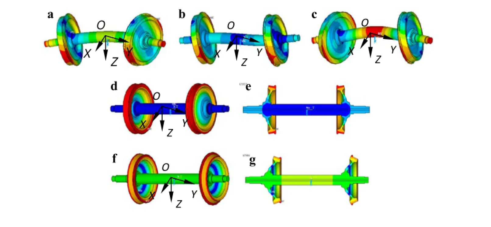
Fig.2 Wheelset modes.a First bending mode 117Hz.b Second bending mode 203Hz.c Third bending mode 350Hz.d First wheel umbrella mode 329Hz.e Cutaway of d.f Second wheel umbrella mode 469Hz.g Cutaway off

Fig.3 Force analysis diagram of fl xible wheelset
Basedonthree-dimensionalfinite-elemen theoryforsolid dynamics,the wheelset differential motion equation of the ith wheelset at time t can be written as

where¨ui(t),ui(t)are the displacement and acceleration vectors of the nodes,respectively,and Miand Kiare the mass and stiffness matrices,respectively.The dimension of the¨ui(t)and ui(t)is the degrees of freedom(DOFs)of the finite-elemen model of the wheelset.The vector Qi(t)contains the external forces acting on the wheelset. The external forces act on the left and right wheelset axle bearings and wheel-rail contact points,so the nonzero components in the vector Qi(t)corresponds to the three DOFs of the nodes near these acting points,that is,the other components in the vector Qi(t)are zero and can be written as

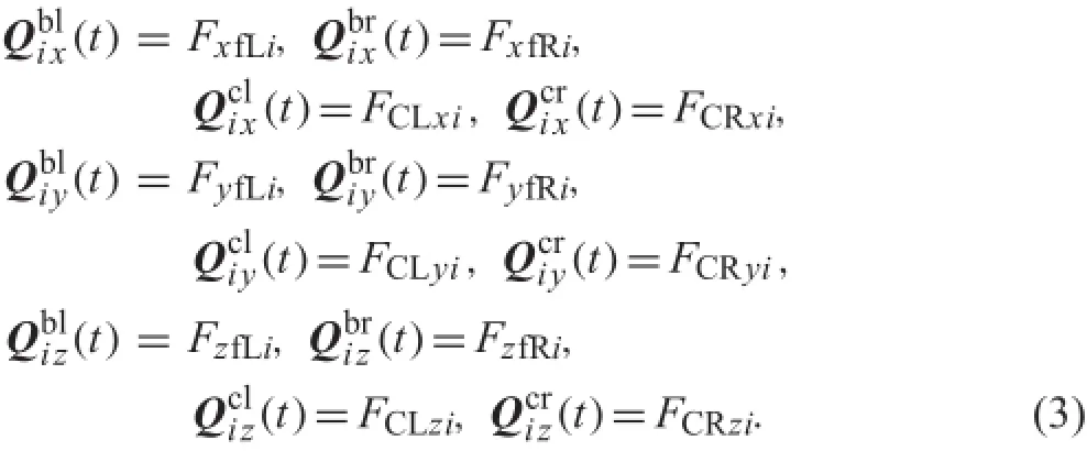
where the superscript k denotes the nodes nearest to the acting points of the four external forces,and bl,br,cl,and cr denote the forces acting on the left and right bearings(primary forces)and the left and right contact points(wheel-rail contactforces),respectively.Thesubscriptsx,y,andzdenote the force components in the three directions,respectively.In this study,the wheel-rail spin moments are ignored.Based onFig.3,thethreeforcecomponentvectorscanbewrittenasUsing the modal superposition method,ui(t)can be written as

where

Niis the total number of modes considered.The subscript k denotes the k-th mode.q is the normal modal coordinate vector,and Φ is the eigenvalue matrix that consists of the column modal vectors{ϕ}ik.
The firs and second derivatives of ui(t)can then be written as

Substituting Eqs.(4)and(6)into Eq.(1),the equation of motion can be expressed as

PremultiplyingthetermsonbothsidesofEq.(7)byΦTiyields

Based on the orthogonality of the eigenvectors with respect to the mass and stiffness matrices,we have that

where I is the identity matrix of the same size as the mass matrix.The elements contained in matrix Ω are the natural circular frequencies.The equation of motion can therefore be decoupled as

where the second derivative of q at each time step can be solved by an explicit integral algorithm.Equations(4)and (6)areusedtocalculatethenodaldisplacement,velocity,and acceleration.Thus,Eq.(1)must be solved using the modal superposition method.
ThemodelproposedinRefs.[17,18]consideredthedeformations of wheelset axle bending in the O-XY and O-ZY planes to have independent effects on the wheel-rail rolling contact behavior.The new fl xible wheelset model accounts for the combined effect of wheelset axle deformations in the two planes.Therefore,this new fl xible wheelset model describes wheelset fl xibility more realistically.
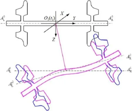
Fig.4 A wheelset moving from its initial reference state O1(t1)to the state O2(t)in the O-YZ plane with a deformation
2.2Coupling of wheel–rail contact model to flexibl wheelset model
The contact model proposed in Ref.[17]cannot be used to consider the effect of the axial deformation of the wheel web.This is because the two wheels of the wheelset were assumedtoberigidandalwaysperpendiculartothedeformed wheelset axle at the connection of the wheels and axle.Note that the deformation of a wheel rim is very slight in the firs three wheelset bending modes and its two umbrella modes. Therefore,the specifi coupling of the wheel-rail contact model to the fl xible wheelset assumes that the cross section of the wheel rim is not deformed.The novel approach of the present wheel-rail model is to consider the deformation characteristics of the wheelset in rolling contact with track rails based on the contact model in Ref.[17].To this end, dummies of the two half-rigid wheelsets are introduced.It is assumed that the partial boundaries of the unchanged cross sections of the wheel rims of the fl xible wheelset always coincide with those of the two wheel rims of the two dummies.Thus,the spatial position of the two dummies can be determined using the wheel rims of the fl xible wheelset.A detailed description of the coupling is provided below.
To make it more convenient to describe the process of wheelset deformation,Fig.4 only illustrates the wheelset deformation in the O-YZ plane.Usually,wheelset motion consists of rigid body motion and elastic deformation.The rigid body motion includes translation and rotation.Translation is expressed by the vector,which indicates thatthe wheelset axial central line moves from the lineto the line.The rotation is expressed by the roll angle,whichdenotesthatthewheelsetaxialcentrallinerotates from the lineto the line.In Fig.4,the red wheelset profil indicates the wheelset deformation caused by the wheelset bending modes.The wheel web umbrella modes are denoted by the blue profiles
The low boundaries of the wheel rims of the dummies of the two half-rigid wheelsets(black profile in Fig.5)always coincide with those of the wheels of the fl xible wheelset with both axle bending and deformed webs(purple and blue profile in Fig.5).The left and right dummies are define as DWL and DWR,respectively.The body coordinate systemof DWR is fi ed on DWR’s center point.The axialways coincides with DWR’s axle central line.Its initial configuratio is parallel to the absolute coordinate system O-XYZ,and its base vector is[iDR1,].DWon consists of translation(indicated by the vecto)and rotation(denoted by the roll angle).
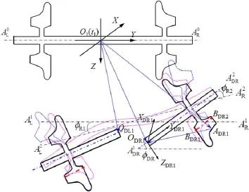
Fig.5 Relationship between the two rigid half-wheelset dummies and the fl xible wheelset
(1)Calculation of φDRBased on the assumption of an undeformed wheel rim,it is possible to finthe lineon the wheel rim that is parallel toat all times.Therefore,can be calculated using the vector.The spatial positions ofthepointsarerelatedtoboththerigidbody motion and fl xible deformations,which can be calculated using the method described in Sect.2.1.As shown in Fig.5, DWR’s roll angleis the sum ofand(caused by the wheelset fl xibility).

The point ADR1on the wheel tread is on the nominal rolling circleoftheDWRwheel.Thevectorcan bewritten in the absolute coordinate system as

In the body coordinate systemof DWR,can be written as

where l0is the distance between the wheelset center and the nominal rolling circle center,and R0is the radius of the nominal rolling circle.
The following equation is used to carry out a transformation between the absolute coordinate system and the body coordinate system:

SubstitutingEq.(14)intoEq.(13),canbewritten as

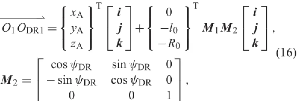
When the wheelset deformation in the plane XOY is considered,can be written aswhere the yaw angle ψDRof DWR is the sum of ψR1from rigid body motion and ψR2from deformation.The position of DWL can be obtained in a similar manner.
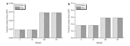
Fig.6 Maximum and minimum of wheel-rail contact forces.a Lateral contact forces.b Vertical contact forces
The wheel-rail contact geometry can then be determined bytherelativespatialpositionsofthetwohalf-rigidwheelset dummies and the rails.The positions of the left and right wheel-railcontactpointscanbecalculatedbasedonthecontact point trace method[19].The normal wheel-rail contact forces are calculated using the Hertzian nonlinear contact springmodel,andthetangentialcontactforcesarecalculated using the model by Shen et al.[21].Compared with the conventional dynamic model[22],the proposed coupling of the wheel-rail contact model to a fl xible wheelset can be used to characterize more clearly the effect of the high-frequency deformations of the two wheels of the fl xible wheelset on the wheel-rail dynamic contact behavior.Compared with the coupling proposed in Refs.[18,23],the coupling in this papercancharacterizetheeffectofboththeaxlebendingand the wheel web deformation on the wheel-rail rolling contact behavior.However,the effect of the change in the wheel rim cross section is neglected since it is small compared to the axle bending and web deformation.
3 Results and discussion
Thissectionconsistsofthreesubsectionsthatshowtheresults anddiscussionsregardingthreetrackirregularityexcitations. The notions used in the three subsections are illustrated in advance.Model I assumes rigid wheelsets,Model II allows for wheel web deformation,Model III allows for wheelset bending,and Model IV allows for both wheelset bending and web deformation.
3.1Effect of excitation of discrete sleepers
A number of side tests have shown that the dynamic behavior of trains operating at high speeds is affected by discrete sleeper supports.Therefore,there is a need to understand the effect of the excitation from the discrete sleepers and the resulting contribution of wheel axle bending and wheel web deformation to wheel-rail rolling contact behavior.Numerical simulations were carried out for a train traveling at 300km/h on a track without irregularities using both the new (considering the effect of wheelset fl xibility)and conventional vehicle-track models.
Figure 6 illustrates the maximum and minimum of the wheel-rail contact forces,including the lateral and normal forces,which are calculated using four vehicle-track dynamics modelsundertheexcitation ofdiscretesupporters. Comparing the results of Models I and II,the maxima of the contact forces remain approximately the same.From the resultsofModelsIandIII,themaximumofthecontactforces in Model III increases owing to the effect of wheelset bending.Therefore,the effect of wheelset bending on wheel-rail contact forces is greater than that of wheel web deformation.
A further investigation into the effect of wheelset fl xibility was conducted by analyzing the contact forces obtained from each of the four models in the frequency domain (Fig.7).Figure7a,b indicates the vertical and lateral contact forces,respectively.High peaks appear at the passing sleeper frequency(fs)and its harmonic frequencies.At 300km/h,fs=138Hz.There are relatively low peaks at fb2=203Hz,characterized using Models III and IV because they consider the three bending modes.Comparedwiththecontributionoftheothermodeson the vertical forces,the second bending mode of the wheelset is the largest.This is because the second bending mode is antisymmetrical and the wheelset motion is more sensitive to this mode with respect to the other modes under the excitation.The lateral wheel-rail forces have a similar profile as shown in Fig.7b.A comparison between Fig.7a and b indicates that the effect of the wheelset fl xibility on the lateral forces is greater than that on the wheel-rail vertical contact force.

Fig.7 Wheel-rail contact forces in frequency domain.a Lateral contact forces.b Vertical contact forces
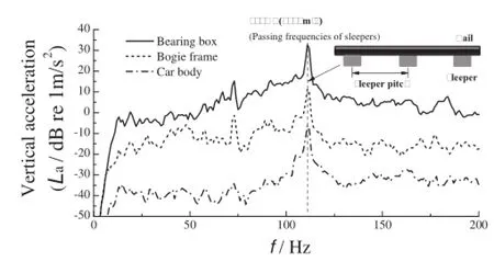
Fig.8 Measured vertical acceleration spectra of a high-speed vehicle at 250km/h
The site tests show the strong dynamical responses of high-speed trains to the excitation of discrete sleepers. Figure8 illustrates the spectra of the measured vertical accelerations of the bearing box,the bogie frame,and the car body of a high-speed vehicle at 250km/h at an operational site.The high peaks occur at 111Hz,which is the passing frequency of the discrete sleepers with a sleeper pitch of 0.629m at 250km/h.The wheel-rail excitation at the passing frequency of the discrete sleepers contributes greatly to the vibration and noise of high-speed trains and tracks at approximately 300km/h.The detailed discussions of this phenomenon are not included in this paper.
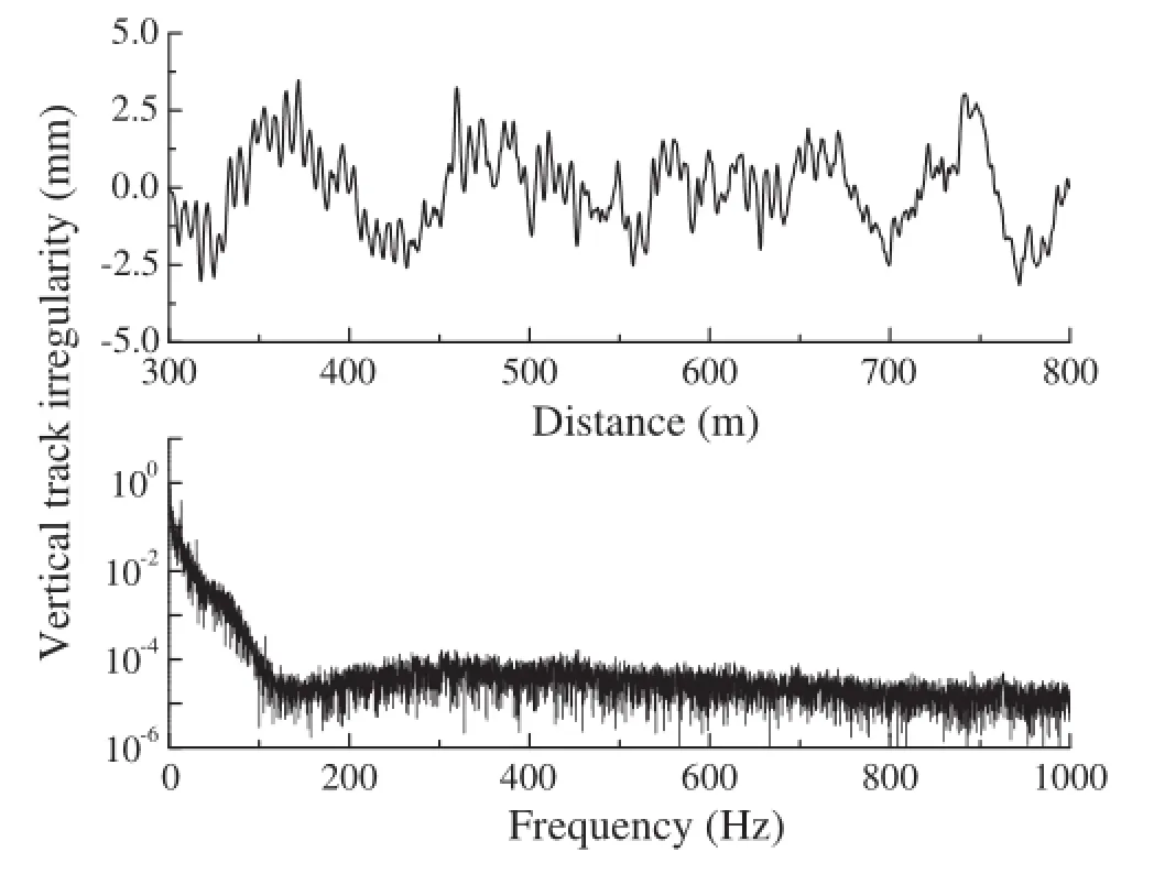
Fig.9 Vertical irregularity measured on left rail
3.2Effect of excitation of measured track irregularity
The effect of wheelset fl xibility on wheel-rail contact behavior was investigated under the excitation of normal track irregularity.The normal track irregularity adopted in the numerical simulations was measured from the operational sites and contains components with short and long wavelengths.Figure9 shows the shapes of the vertical irregularity measured from the left rail of a high-speed track in the time and frequency domain.The main components are distributed in a frequency range of under 100Hz at 300km/h.In other words,the passing frequencies of irregularity components with high amplitudes are less than 100Hz at 300km/h.
Figure 10 indicates the contact forces in both the time and frequency domains,calculated using Models I and IV undertheaforementionedirregularityexcitationat300km/h. In the time domain(Fig.10a),there is no clear difference between the results of Models I and IV.In the frequency domain(Fig.10b),there are small peaks at frequencies of fs,fb2,and fb3in the lateral contact force obtained by Model IV.fsis the passing frequency of the discrete sleepers.fb2and fb3are the frequencies of the second and third bending resonances of the wheelset,respectively.Therefore, the excitations of the discrete sleeper support and the second and third bending modes of the wheelset have a larger contribution to the lateral wheel-rail force than the firs bending mode.The vertical wheel-rail forces calculated by Models I and IV present small peaks at fs.Models I and IV cantherefore characterize the response to the excitation of the discrete sleeper support under the present conditions,which include the normal track irregularity excitation and the operation speed.However,the contribution of the firs bending resonance of the wheelset and umbrella modes of the wheel webs under the vertical harmonic irregularities is too small to be reflected

Fig.10 Wheel-rail contact forces in a time domain and b frequency domains
The differences in the lateral contact forces calculated using the two models around the frequencies of fb2and fb3are magnifie and presented in Fig.11.The second and third bending modes of the wheelset are excited,but the two web umbrellamodesarenot excited underthepresent calculation conditions.
It should be noted that,although the contribution of these excited wheelset resonance modes are quite small,they can cause polygonal wear on the wheels,which leads to strong vibrations and noise.

Fig.11 Magnification of lateral contact forces in frequency domain around frequencies of fb2(upper)and fb3(lower)
3.3Effect of harmonic track irregularity excitations
Note that under the excitation of the sleepers(discussed in Sect.3.1)and the measured track irregularity(discussed in Sect.3.2),the wheel web umbrella modes are not excited. The objective of this section is to determine the effect of the two umbrella modes of the wheel webs on wheel-rail contact behavior using other forms of wheel-rail excitation.Harmonic irregularities with two fi ed wavelengths are used as the wheel-rail excitations.The two wavelengths are 0.25m(defineas IRR-I)and 0.18m(define as IRR-II),respectively.The corresponding excitation frequencies at 300km/h are therefore close to the eigenfrequencies fu1and fu2of the two lowest umbrella modes. The amplitude is 0.01mm.In the numerical investigation, the operation speed is from 200 to 400km/h at intervals of 25km/h.
Figure12a,billustratesthemaximaandfluctuatin amplitudes of the lateral wheel-rail contact forces,respectively, calculated using Models I,II,and IV under the excitations of track irregularity IRR-I.Figure12c,d illustrates the maxima and the fluctuatin amplitudes of the vertical wheel-rail contact forces.Under IRR-I excitation and at speeds of 200-400km/h,the responses characterized by Models I and II are relatively close.A small difference in their results occurs around 300km/h since the resonance at fu1is excited.This indicates that the effect of the umbrella mode resonances on the wheel-rail contact forces is quite small under the vertical harmonic irregularities.Furthermore,the difference in the lateral wheel-rail forces of the two models is slightly larger than that of the vertical wheel-rail contact forces.The maxima and fluctuatinamplitudes of the vertical contact forcescalculatedusingModelsIandIIincreasewithincreasing speed,but the rate of increase for the lateral forces are relatively small compared with the rate of increase for thevertical wheel-rail contact forces.The maxima and the fluc tuating amplitudes of the results calculated using Model IV considering the effect of the wheelset axle bending mode resonances are much larger than those of Models I and II at speeds of less than 250km/h.The reason for the results is that the deformation at the contact for the umbrella modes is mainly directed in the lateral direction,while the wheel-rail contact forces mainly act in the vertical direction.In contrast tothis,themodaldeformationsofthebendingmodescontain considerable vertical components and are thereby excited. For speeds between 200 and 250km/h,the passing frequencies of IRR-I are near the frequencies fb1and fb2(117 and 203Hz)ofthebendingresonanceofthewheelsetaxle,which are easily excited under these conditions.When the speed is greater than 250km/h,the calculated results of the three models are close.When the speed approaches 325km/h, the passing frequency of IRR-I is close to fb3=350Hz, whichisthethirdbendingresonantfrequencyofthewheelset axle.Therefore,there is a small local peak at 325km/h in Fig.12b.
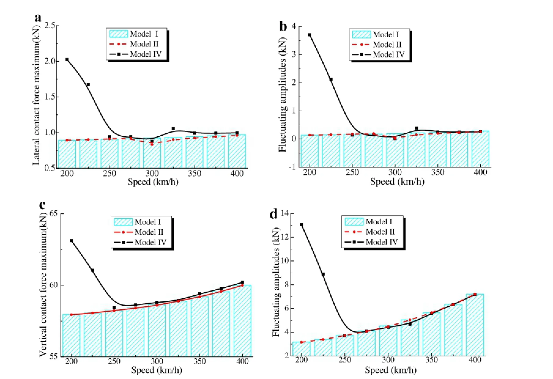
Fig.12 Characteristics of wheel-rail contact forces under IRR-I excitation.a Maximum of lateral forces.b Fluctuating amplitudes of lateral forces.c Maximum of vertical forces.d Fluctuating amplitudes of vertical forces
Figure 13 shows the calculated wheel-rail contact forces using Models I,II,and IV under IRR-II excitation.The characteristics of Fig.13 are similar to those of Fig.12. The difference between the results of Models I and II is quite small over the entire speed range.In a speed range of 250-400km/h,the results of the three models are also relatively close.This means that the effect of the two umbrella modes of the wheel webs on the wheelrail contact forces are quite small under vertical harmonic irregularities,namely,the vertical harmonic irregularities. Compared to the results of Models I and II,the effect of the axle bending on the wheel-rail contact forces is much larger.
To better understand the changes in the frequency domain due to the effect of wheelset fl xibility at speeds of 200-400km/h,contours of the lateral contact forces were generated for different speeds and frequencies.Figures14 and 15 show the contours of the lateral contact forces under IRR-I and IRR-II excitations,respectively.firr1and firr2are the excitation frequencies(or passing frequencies)of IRR-I and IRR-II,respectively.Their values increase with increases in speed.
Figure14a,b shows the results calculated using Models I and IV,respectively.Figure14a,b,displays two brightly colored bands in which the frequency increases as the speed increases.They represent the larger lateral wheelrail contact forces at the passing frequencies,firri,of IRR-i (i=I or II)and the second harmonic frequency,2 firri, of firri(i=1 or 2),respectively.The subscript i=1,2 denotes IRR-I and IRR-II,respectively.This indicates thedominant effects of the irregularities on the lateral forces. At speeds of 200-225km/h,the two bright bands occurred at fb2and 2 fb2and indicate the prominent contribution of the excited second bending mode to the lateral wheel-rail contact forces,as shown in rectangles P1in Figs.14b and 15b.The dark band at 300km/h,shown in rectangle P2in Fig.14b,represents the decrease in the lateral forces owing to the resonance of the firs wheel umbrella mode,which can be seen in Fig.12.Furthermore,the dark band indicates that the firs umbrella mode at 300km/h affects the lateral wheel-rail contact forces in the entire frequency range analyzed.The area in rectangle P3in Fig.14b is brighter.This is because firr1is close to fb3at a speed of 325km/h.
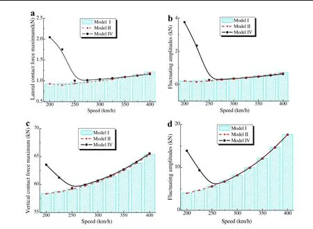
Fig.13 Characteristics of wheel-rail contact forces under IRR-II excitation.a Maximum of lateral forces.b Fluctuating amplitudes of lateral forces.c Maximum of vertical forces.d Fluctuating amplitudes of vertical forces

Fig.14 Contours of lateral contact forces in frequency domain using a Model I,and b Model IV under IRR-I excitation
Figure15a,b shows the results calculated using Models I andIV,respectively.Theeffectsoftheirregularityexcitations are demonstrated by the main bright bands.The difference betweenFig.15aandbismarkedbyrectangleP1inthespeedrange of 200-225km/h,which is caused by the excited second wheelset bending mode.The excitation frequency of 469Hz of IRR-II is equal to the frequency of the second umbrella mode of the wheel web.However,either the secondumbrellamoderesonanceofthewheelwebisnotexcited or this model does not account for any contribution to the lateral wheel-rail forces under vertical harmonic irregularities,which include the vehicle operating on a straight track, theverticalirregularityexcitations,andtheconsideredspeed range.
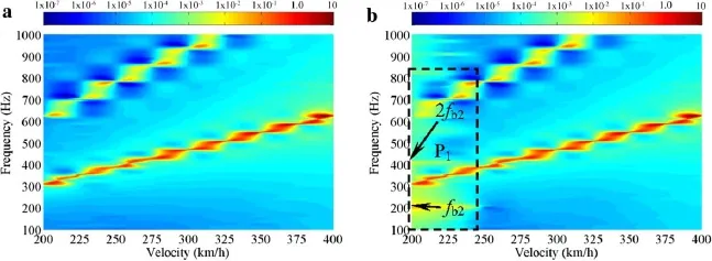
Fig.15 Contours of lateral contact forces versus frequencies and speeds,calculated using a Model I,and b Model IV under IRR-II excitation
4 Conclusions
In this paper a conventional vehicle-track model was extended to take into account the fl xibility of wheelsets. Thefl xibilitywaspresentedbythewheelsetbendingmodes and wheel umbrella modes.The section configuratio of the wheelrimwasassumedtoberigid.Afl xiblewheelsetmodel was created based on three-dimensional finite-elemen theory and the modal superposition method.Using the new and conventional models,numerical simulations were carried out to investigate the effect of wheelset bending modes and wheel umbrella modes under different excitations and speeds between 200 and 400km/h.The following conclusions can be drawn from the results:
(1)For a vehicle operating at high speeds on a tangent track and under the measured normal track irregularities,the wheelset bending modes are more easily excited than the wheel web umbrella modes.
(2)Underverticalharmonicirregularities,thecontributionof the wheel web umbrella modes to the wheel-rail contact forcesisrelativelysmallcomparedtothatofthewheelset bending modes and can be neglected.
(3)The proposed vehicle-track dynamic system model can effectively reflec the effect of wheelset fl xibility on wheel-rail rolling contact.
Further improvements to the model will allow it to help investigate themechanisms behind thegeneration anddevelopment of wheel-rail wear and noise.The firs improvement isthat,eitherthelateralexcitations ofthesystemoravehicle operating on a sharply curved track should be investigated. In addition the wheelset inertial effect due to its rotation will be taken into account.
AcknowledgmentsThe present work was supported by the National BasicResearchProgramofChina(Grant2011CB711103),theNational Natural Science Foundation of China(Grants U1134202,U1361117), the Program for Changjiang Scholars and Innovative Research Team in University(IRT1178),the 2014 Doctoral Innovation Funds of Southwest Jiaotong University,and the Fundamental Research Funds for the Central Universities.
Appendix
Appendix 1
See Table1.

Table 1 Vehicle and track parameters
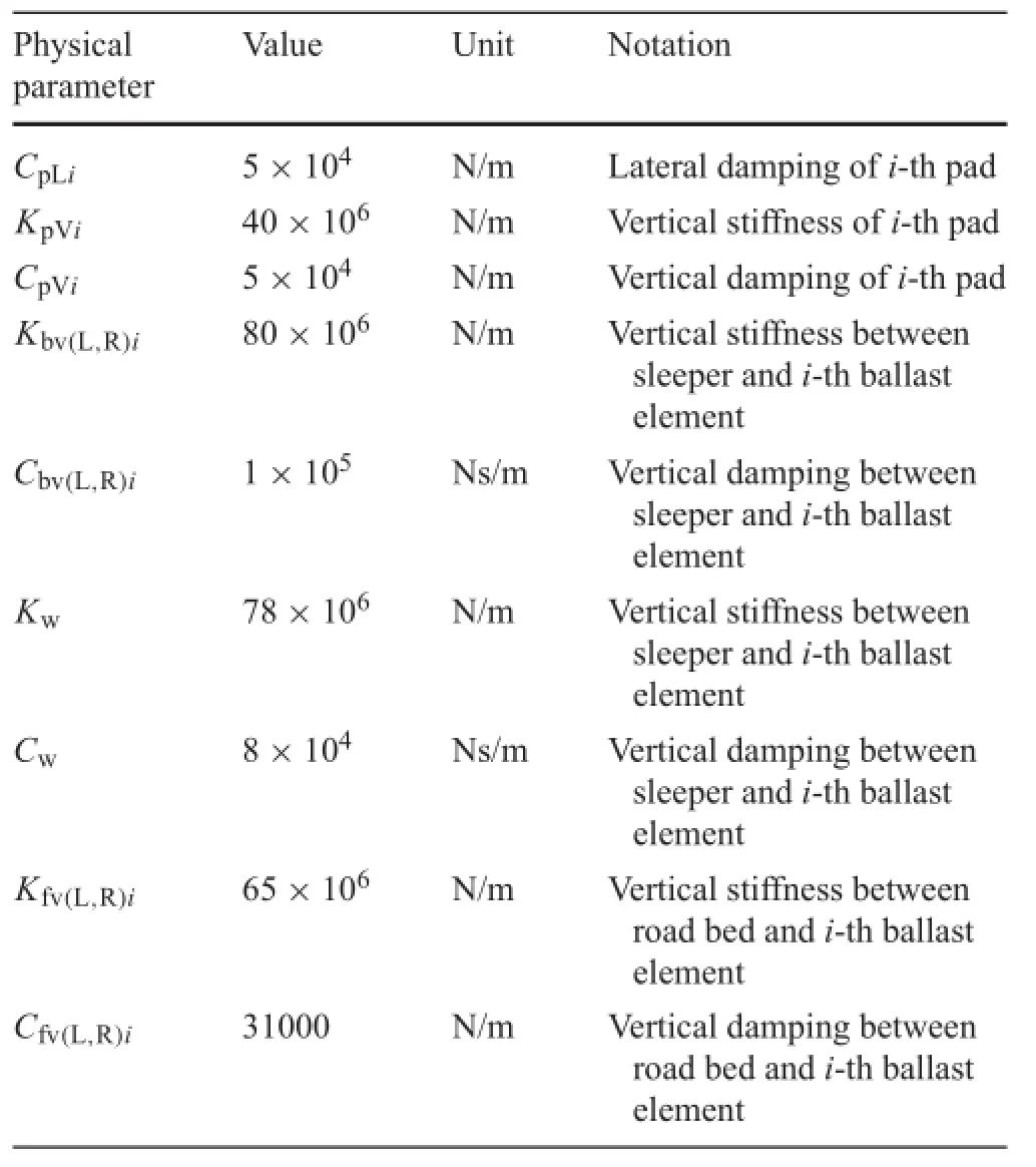
Table 1 continued
Appendix 2
See Table2.
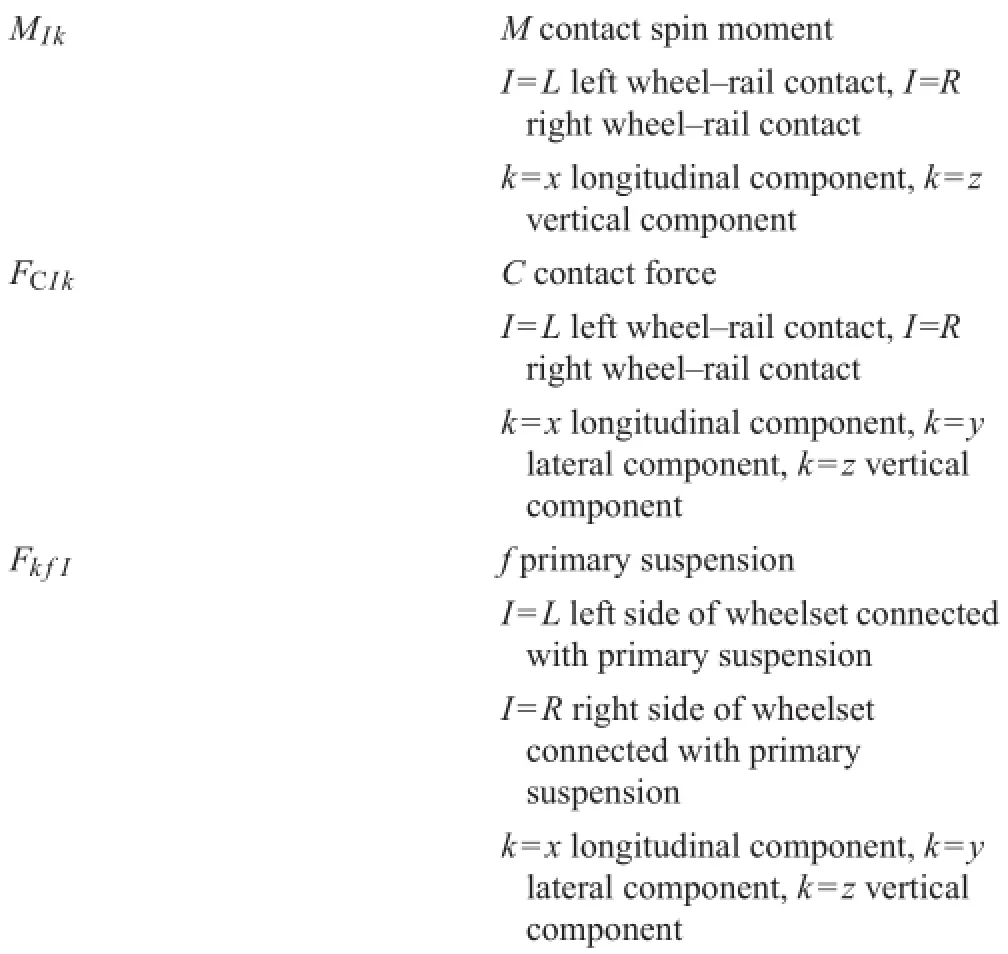
Table 2 Quantities involved in derivation of equations of motion of wheelset bending
References
1.Jin,X.S.,Xiao,X.B.,Ling,L.,et al.:Study on safety boundary for highspeed train running in severe environments.J.Rail Transp.1, 87-108(2013)
2.Jin,X.S.,Wen,Z.F.,Wang,K.Y.,et al.:Three-dimensional traintrack for study of rail corrugation.J.Sound Vib.293,830-855 (2006)
3.Grassie,S.,Kalousek,J.:Rail corrugation,characteristics,cause and treatments.Proc.Inst.Mech.Eng.F 207,57-68(1993)
4.Nielsen,J.C.O.,Lundén,R.,Johansson,A.,etal.:Train-trackinteractionandmechanismsofirregularwearonwheelandrailsurfaces. Veh.Syst.Dyn.40,3-54(2003)
5.Nielsen,J.C.O.,Ekberg,A.,Lundén,R.:Influenc of short-pitch wheel/railcorrugationonrollingcontactfatigueofrailwaywheels. J.Rail Rapid Transit 219,177-188(2005)
6.Oostermeijer,K.H.:Review on short pitch rail corrugation studies. Wear 265,1231-1237(2008)
7.Chaar,N.:Wheelset structural fl xibility and track fl xibility in vehicle/track dynamic interaction,[Ph.D.Thesis],Royal Institute of Technology,Stockholm(2007)
8.Popp,K.,Kruse,H.,Kaiser,I.:Vehicle/track dynamics in the midfrequency range.Veh.Syst.Dyn.31,423-463(1999)
9.Szolc,T.:Medium frequency dynamic investigation of the railway wheelset-track system using a discrete-continuous model.Arch. Appl.Mech.65,30-45(1998)
10.Szolc,T.:Simulation of bending-torsional-lateral vibrations of the railway wheelset-track system in the medium frequency range. Veh.Syst.Dyn.30,473-508(1998)
11.Popp,K.,Kaiser,I.,Kruse,H.:System dynamics of railway vehicles and track.Arch.Appl.Mech.72,949-961(2003)
12.Meinders,T.:Modeling of a railway wheelset as a rotating elastic multibody system.Mech.Dyn.Probl.20,209-219(1998)
13.Baeza,L.,Vila,P.,Xie,G.,etal.:Predictionofrailcorrugationusing a rotating fl xible wheelset coupled with a fl xible track model and a non-Hertzian/non-steady contact model.J.Sound Vib.330, 4493-4507(2011)
14.Torstensson,P.T.,Pieringer,A.,Nielsen,J.C.O.:Simulation of rail roughness growth on small radius curves using a non-Hertzian and non-steady wheel-rail contact model.In:Proceedings of the Ninth International Conference on Contact Mechanics and Wear of Rail/Wheel Systems,Chengdu,August(2012)
15.Torstensson,P.T.,Nielsen,J.C.O.:Simulationof dynamic vehicletrack interaction on small radius curves.Veh.Syst.Dyn.49,1711-1732(2011)
16.Andersson,C.,Abrahamsson,T.:Simulation of interaction between a train in general motion and a track.Veh.Syst.Dyn. 38,433-455(2002)
17.Zhong,S.Q.,Xiao,X.B.,Wen,Z.F.,et al.:The effect of first-orde bending resonance of wheelset at high speed on wheel-rail contact behavior.Adv.Mech.Eng.2013,19(2013).doi:10.1155/2013/ 296106
18.Zhong,S.Q.,Xiao,X.B.,Wen,Z.F.,et al.:A new wheel-rail contact model integrated into a coupled vehicle-track system model considering wheelset bending.In:Pombo,J.(ed.)Proceedings of the Second International Conference on Railway Technology Research,Development and Maintenance,2014.Paper 10.Civil-Comp Press,Stirlingshire
19.Wang,K.W.:Wheel contact point trace line and wheel/rail contact geometry parameters computation.J.Southwest Jiaotong Univ.1, 89-99(1984)
20.Xiao,X.B.,Jin,X.S.,Wen,Z.F.,etal.:Effectoftangenttrackbuckle on vehicle derailment.Multibody Syst.Dyn.25,1-41(2011)
21.Shen,Z.Y.,Hedrick,J.K.,Elkins,J.A.:Acomparisonofalternative creep force models for rail vehicle dynamic analysis.In:Proceedings of the Eighth IAVSD Symposium,591-605.MIT,Cambridge (1983)
22.Zhai,W.M.:Vehicle/Track Coupling Dynamics,3rd edn.Chinese Science Press,Beijing(2007)
23.Zhong,S.Q.,Xiong,J.Y.,Xiao,X.B.,et al.:Effect of the firs two wheelset bending modes on wheel-rail contact behavior.J.Zhejiang Univ.Sci.A 15,984-1001(2014)
30 October 2014/Revised:17 November 2014/Accepted:5 January 2015/Published online:25 August 2015
✉Xuesong Jin
xsjin@swjtu.cn
1State Key Laboratory of Traction Power,Southwest Jiaotong University,No.111,First Section,North of Second Ring Road,Chengdu 610031,China
杂志排行
Acta Mechanica Sinica的其它文章
- Correcting the initialization of models with fractional derivatives via history-dependent conditions
- Tomographic PIV investigation on coherent vortex structures over shark-skin-inspired drag-reducing riblets
- Analysis of the geometrical dependence of auxetic behavior in reentrant structures by finit elements
- The equilibrium stability for a smooth and discontinuous oscillator with dry friction
- Impact toughness of a gradient hardened layer of Cr5Mo1V steel treated by laser shock peening
- Why a mosquito leg possesses superior load-bearing capacity on water:Experimentals
