Analysis of torque transmitting behavior and wheel slip prevention control during regenerative braking for high speed EMU trains
2016-09-06KunXuGuoQingXuChunHuaZheng
Kun Xu·Guo-Qing Xu·Chun-Hua Zheng
Analysis of torque transmitting behavior and wheel slip prevention control during regenerative braking for high speed EMU trains
Kun Xu1,2·Guo-Qing Xu3·Chun-Hua Zheng1
©The Chinese Society of Theoretical and Applied Mechanics;Institute of Mechanics,Chinese Academy of Sciences and Springer-Verlag Berlin Heidelberg 2016
AbstractThe wheel-rail adhesion control for regenerative braking systems of high speed electric multiple unit trains is crucial to maintaining the stability,improving the adhesion utilization,and achieving deep energy recovery.There remain technical challenges mainly because of the nonlinear,uncertain,and varying features of wheel-rail contact conditions.This research analyzes the torque transmitting behavior during regenerative braking,and proposes a novel methodology to detect the wheel-rail adhesion stability. Then,applications to the wheel slip prevention during brakingareinvestigated,andtheoptimalslipratiocontrolscheme isproposed,whichisbasedonanoveloptimalreferencegenerationoftheslipratioandarobustslidingmodecontrol.The proposed methodology achieves the optimal braking performancewithoutthewheel-railcontactinformation.Numerical simulationresultsforuncertainslipperyrailsverifytheeffectiveness of the proposed methodology.
KeywordsHigh speed electric multiple unit(EMU)train· Regenerative braking·Wheel-rail adhesion·Optimal slip ratio
1 Introduction
Fast-pacedtechnologicaladvancesinelectricrailwaypropulsion systems have significantl promoted the rapid development of high speed railways[1-3].This,in turn,produces higher demands for the safety and energy savings of high speed electric multiple unit(EMU)trains.The brake system isparticularlyimportantbecauseofitsdirectimpactonsafety andenergyconsumption.Brakesystemsfallintotwogroups: electrical braking(i.e.,regenerative braking)and mechanicalbraking.Theregenerativebrakingsystems(RBSs),which use the electric motors as the actuators to generate the braking torque,have many merits.The bi-directional power flw oftheelectricmotor/generatorcantransferthekineticenergy of an EMU train into electric energy that may be fed back to the grid so as to achieve high energy savings[4,5].Moreover,the electric braking torque generated from the motor has wider bandwidth than the frictional braking mechanism, which leads to a very fast braking response[6,7].
A sophisticated regulated RBS via the adhesion control contributes not only to maintain the wheel-rail adhesion stability but also to maximize the adhesion utilization for shorteningthestoppingdistance,whilereducingtheabrasion ofwheelsandrailssoastoprolongtheservicelife.Moreover, it is beneficia to recover a significan quantity of energy[8]. There remain technical challenges in the adhesion control of RBS mainly because of the complex wheel-rail contact conditions.The adhesion phenomena between the wheel and the railisnonlinear,uncertain,andtime-varying[9,10].Withthe extensivespreadingofhighspeedrailsworldwide,thewheelrail conditions become more complex than before,e.g.,low griprailscoveredwithsnoworiceincoldareas.Additionally, with the increasing running speed of EMU trains presently, the adhesion stability during braking under various grip con-ditionsmustbeensured.Therefore,itiscrucialtodeveloping advanced adhesion control methodologies under complex grip conditions.
The wheel-rail adhesion force has a close relation to the slip ratio[8-10].A proper slip ratio is beneficia to generate theadhesionforce.However,theexcessiveslipratiomaylead toasignifican reductionintheadhesionforcethatwillcause unstable wheel skidding or even locking.There is a critical operation point between the stable adhesion state and the unstable skidding state,wherein the adhesion force reaches amaximum.Therefore,thecriticalpointisalsonamedasthe optimaloperationpoint,whereintheslipratioisnamedasthe optimal slip ratio.Generally,the following crucial problems are considered in adhesion control:(1)to determine whether the current adhesion state is stable or not;(2)to maintain the adhesion stability particularly for low grip conditions. If severe wheel skidding is detected,the adhesion controller directly intervenes by regulating the traction/braking torque to maintain the operation point in the stable region.It is far better to maximize the wheel-rail adhesion so as to improve the traction/brake performance,especially under low grip conditions for fast running speed.
The adhesion control during traction or braking has been studied in the literature[10-20].Several signals have been used to identify the wheel adhesion state and to prevent the unstable wheel skidding,including the speed difference between the wheel and the chassis,the differential signals of the wheel speed,and the slip ratio.Accordingly,existing adhesion control studies mainly fall into two categories:one is the conventional correction-based methodology;the other is the slip-based control.
Correction-based control methods use the speed differenceorthedifferentialwheelspeedtodeterminetheadhesion state[8].Ifasevereslippingduringtractionoraskiddingduringbrakingisdetected,actuatorsdecreasethedrivetorqueor braketorqueaccordinglytoretaintheadhesion.Afterreturning to the stable adhesion state,the drive or brake torque will be slowly increased again,which makes the operation point far away from the adhesive peak,therefore leading to a low utilization of the wheel-rail adhesion.Additionally, these methods usually need to determine a preset value by experiments in advance,which may function under a certain specifi condition without adaptation.In some applications, the worst condition(e.g.,a very slippery wheel-rail condition)is considered to ensure the safety,which,however, sacrifice the optimal performance.
The slip-based control drew more research interest recently due to the inherent relation between the slip ratio and the adhesion force[15-18,21].Controlling the slip ratio directly around its optimal value acquires the maximum utilization of the wheel-rail adhesion.However,determining the optimal slip ratio is very difficul because of the uncertainty and the variety of the wheel-rail contact conditions. To improve the adaptability associated with changed wheelrail conditions,some studies attempt to search the optimal point online[15-18].A methodology to generate the slip ratio reference that is adaptive to various wheel-rail conditions is proposed[15,16],which,however,may be affected by the measurement noise and system uncertainties.Fuzzy logicisintroducedtogeneratetheoptimalslipratiofromseveral typical wheel-rail contacts[17,18,21],which is still not the actual optimal value.We have proposed a novel adhesion stability detection methodology and slip prevention control strategiesforwheeledgroundvehicles[22],which,however, only investigates the traction manoeuver under low speeds that omits the resistance in the analysis.
In this research,the torque transmitting behavior(from the input of the regenerative braking torque to the output of the adhesion torque)during regenerative braking is analyzed basedonthederivedtorquetransferfunction.Itisprovedthat the stability of the torque transfer function is equivalent with the wheel-rail adhesion stability that is composed of the slip ratio and the optimal slip ratio.Then,the optimal slip rate control for regenerative braking is proposed based on the optimal slip ratio generation and the sliding mode control in order to achieve the optimal wheel slip prevention during braking.Theproposedmethodologyfunctionstoachievethe optimalregenerativebrakingperformancewithoutthewheelrail contact knowledge.
2 Torque transfer function of the wheel-rail contact
2.1Longitudinal braking dynamics
The longitudinal braking dynamics of EMU trains is presented by a simplifie single-axel model as shown in Fig.1a, which describes the fundamental dynamics during braking. The dynamic equations are shown as below.

where Tbis the braking torque;Tdand Fdare the adhesion torque and force,respectively;Fzis the wheel normal force; Fdris the fitte total resistance;c0,c1,c2are the fittin coefficients ω and V are the wheel rotational speed(rad/s)and trainspeed(m/s),respectively;r istheeffectivewheelradius.
Wheels and rails are not rigid,so that there is a contact patch due to the elastic contact deformation caused by the normal load between the wheel and the rail,as shown in Fig.1a.Hertz has proven that the shape of the contactpatch is elliptical[11,23].Such a contact patch generates the adhesion region and the slip/skid region due to the tension deformation or compression deformation.When the longitudinal force increases,the adhesion region is reduced,while theslip/skidregionisincreased.Ifonlytheslip/skidregionis left,the wheel spinning/locking phenomena will occur.The slip ratio define in Eq.(5)quantifie the difference between the wheel speed and the train speed.

Fig.1 Wheel rail contact and the μ-λ curve.a Wheel-rail contact.b Typical wheel-rail adhesion curves

Figure1bshowsthetypicalμ-λrelationshipswithvarious rail conditions[11,18,24].The adhesion coefficien behaves as a nonlinear function of the slip ratio.There is a critical operation point(i.e.,the peak point of the curve),wherein the optimal slip ratio and the maximum adhesion coefficien are reached.If the slip ratio is lower than the optimal value, the operation point is the stable adhesion.If the slip ratio is greater than the optimal value,it is an unstable operation point,wherein further increase of the slip ratio will lead to a significan reduction of the adhesion coefficient Additionally,in the stable region,the slope of the curve g=Δμ/△λ is positive.While in the unstable region,it is g<0.
The shapes of the curves depend on the wheel-rail contact conditions.For example,the medium on the wheel tread and the rail surface(e.g.,ice,snow,frost,rain,or oil)may affect the adhesion ability.In low grip contact conditions, the drive wheels are prone to spin during traction and lock duringbraking,leadingtosevereadhesionlossandabrasion.
2.2Linearized torque transfer function
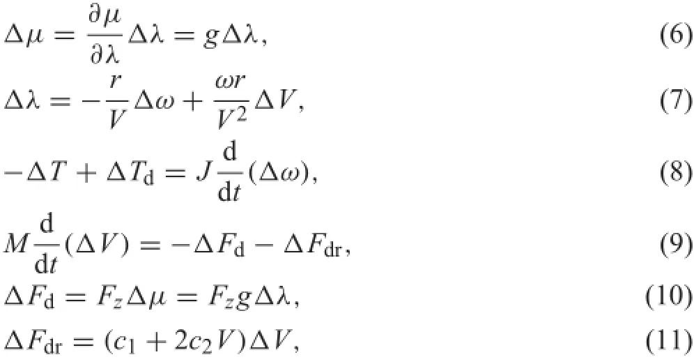
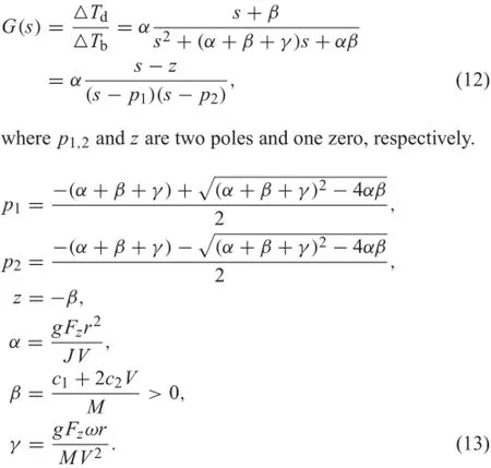
As the wheel-rail contact conditions are complex and uncertain,thispaperaimstodevelopanovelmethodologythatmay be independent of the specifi wheel-rail adhesion condi-tion.Inthispaper,wewillinvestigatethewheel-railadhesion fromthetorquetransmittingpointofview.Thetransferfunction from the wheel regenerative braking torque to the wheel adhesiontorquewillbederivedfirst Asthebrakingdynamics isnonlinearmainlybecauseofthewheel-railcontactfeatures andtheresistantforce,thesmallsignallinearizationtheoryis utilized here to obtain the linearized models as shown in the linearized equations(6)-(11).The system signal flw graph is presented in Fig.2.The transfer function G(s)is finall derived in Eq.(12)using Mason’s gain formula.
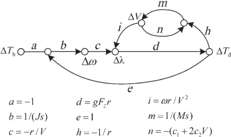
Fig.2 The signal flw graph of the linearized braking dynamics
3 Analysis of torque transmitting behavior
3.1Analysis in the frequency domain
The regenerative braking system utilizes the electric motor to generate the fast braking torque without the conventional frictional braking effect,which is an advantage in estimating the load torque,i.e.,the wheel-rail adhesion torque of the motor driving system.In this section,the torque transmitting behavior from the braking torque to the wheel-rail adhesion torque is analyzed based on the torque transfer function.
Remark I During regenerative braking,the stability of the wheel-railadhesionisequivalenttothestabilityofthetorque transfer function.Specificall,(1)in the stable region of wheel-rail adhesion wherein g>0,the open-loop transfer function in Eq.(12)is stable,i.e.,both of the two poles are located in the left s-plane;(2)in the unstable region of wheel-rail adhesion wherein g<0,the open-loop transfer function in Eq.(12)is unstable,i.e.,there is one pole located in the right s-plane.
Proof According to the linearized open-loop transfer function G(s)atanoperationpoint inEq.(12),thepoleshave the following relationship.

Inthestableadhesionregionoftheμ−λcurvesinFig.1b, the slope of the stable region is positive,i.e.,g>0.The following relations are further derived in Eq.(15),which indicates that the two poles are both negative and located in the left half s-plane.Therefore,the open-loop system is stable.

In the unstable skidding region,the slope of the curve is negative,i.e.,g<0.The relations in Eq.(16)are derived, which indicates that there are one positive pole and one negative pole.The system is unstable.

The remark is thus proved.
3.2Analysis in the time domain
RemarkIdemonstratesthatthestabilityofthetorquetransfer function is consistent with the adhesion stability indicated in the μ-λ curves.Therefore,the wheel-rail adhesion stability during regenerative braking can be determined via the poles of the torque transfer function,instead of comparing the slip ratio and the optimal slip ratio.However,the poles of the torquetransferfunctionfunctionaredifficul todetermineon line due to the unknown parameters of the wheel rail contact (i.e.,the slope g).We further investigate the torque transmittingbehaviorinthetimedomainandderivethefollowing remark.Theproofoftheremarkissimilartotheacceleration case which can be referred to in Ref.[25].
Remark II Considering a variation of the wheel regenerative braking torque at an operation point and introducing a new term named as the torque transmitting factor in the time domain as shown in Eq.(17),the sign of the torque transmitting factor indicates the stability of the wheel-rail adhesion,i.e.,(1)the sufficien and necessary condition for the operation point being unstable(i.e.,g<0)is Eq.(18); (2)the sufficien and necessary condition for an operation point being stable(i.e.,g>0)is Eq.(19).

The remark above indicates that in the stable region, increasingthemotorregenerativetorqueleadstoanincreased adhesion torque.In the unstable region,the adhesion torque is contrary.The adhesion stability in turn can be determined by investigating the torque transmitting behavior in the time domain.
3.3Adhesion torque estimation
The wheel regenerative braking torque is measured directly from the motor current.However,the wheel-rail adhesion torque cannot be measured directly,which has to be estimated.As there is only one kind of actuator torque,i.e.,the motor’s regenerative torque in the regenerative braking system,it iseasy to estimate the adhesion torque[19,20,24,26]. The adhesion torque can be regarded as a load disturbance from the motor dynamic equation point of view.We design the following estimator of the adhesion torque that uses the measured motor torque Tband the wheel rotational speed ω. As the measurement of ω usually contains noise,an additional Kalman filte can be used.
LetˆTdbe the estimated actual adhesion torque,then the estimation error is,

The designed dynamics of the estimation error is,

Then,the estimation equation is derived as shown in Eq.(22)with the assumption of the piecewise˙Td=0.

4 Applications to wheel slip prevention during regenerative braking
4.1Objectives of regenerative braking control
The objectives of the regenerative braking control mainly include ensuring the safety or stability,improving the adhesion utilization,and achieving deep energy recovery.Figure 1b indicates that both the safety and large adhesion utilization can be realized by maintaining the slip ratio at its optimalvalue.Thefollowinganalysisaddressestherelationship between the slip prevention and the energy recovery. Duringregenerativebraking,thekineticenergyofthetrain is transmitted into electricity and fed back into the grid. Figure 3 shows the power flw derived from the braking dynamics equations,where the term FdVλ is the power loss induced by the wheel-rail friction.From the energy transfer point of view,the smaller the slip ratio is,the smaller is the power loss.Therefore,in order to improve the energy recovery,the slip ratio is expected to be as small as possible. Nevertheless,from the adhesion curve point of view,a certain quantity of slip ratio is essential to improve the adhesion force.Therefore,the slip ratio should be maintained around theoptimalslipratiosoastoensurethestabilityandimprove the adhesion while making the wheel/rail friction loss small.
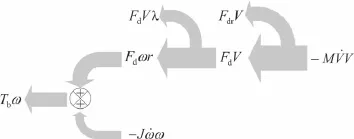
Fig.3 Powerflwduringregenerativebraking.Duringbraking,˙ω and ˙V are both negative
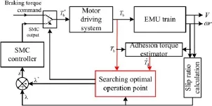
Fig.4 Overall control scheme
4.2Overall control scheme
The torque transmitting behavior can reflec the wheel-rail adhesion stability from the aforementioned analysis.In this section,we will investigate its feasibility with applications to wheel slip prevention during regenerative braking.Figure 4 shows the overall control structure,which involves two subsystems:(1)the optimal slip reference generation and (2)the nonlinear slip ratio controller.This control methodology aims to maintain the slip ratio at its optimal reference by regulating the regenerative braking torque,based on which the maximum adhesion force and the shortest stop time can be achieved.
4.3Optimal slip reference generation
Due to the uncertainty of wheel-rail contact conditions,the optimal slip reference is difficul to obtain.We propose a methodology to determine the optimal slip reference via capturing the optimal operation point via monitoring theadhesion torque.We design the following steps to determine the optimal operation point during braking.
Step 1:Themotorgeneratesanincreasedregenerativebrakingtorque,sothatapositive△Tb(t)isimplemented. Step 2:Estimating the wheel-rail adhesion torque,and calculating the differential signal△Td(t).
Step 3:If△Td(t=k−1)>0 and△Td(t=k)≤0, the optimal operation point occurs during the time interval t∈(k−1,k],go to step 5;else,return to step 2.
Step 4:Atthesteadystateofthecontroller,if|△Td(t)|>ξ, where ξ is a preset positive value,go to step 1.
Step 5:The optimal slip ratio is approximately determined, i.e.,λ∗≈λ(t=k−1).
4.4Sliding mode control design
The sliding mode control(SMC)is used for the wheel slip prevention because of its practical simplicity and robustness against parameter variations and disturbances.We derive the stateequationinEq.(23)fromEqs.(1)-(5)thattakestheslip ratio as the state variable.

where,

The control objective of the sliding mode controller is to reach and remain in the sliding surface that is define as

The sliding condition is presented in Eq.(26),wherein η is a strictly positive constant,sat(·)is a saturation function forchatteringreductionwiththeboundarylayerwidthψ that is chosen carefully taking into account the frequency range of the unmodelled dynamics.

The sliding mode control framework includes two terms: one is the equivalent control term that may maintain the slip ratio in the sliding surface with the assumption of a completely known system;the other is a switching term that
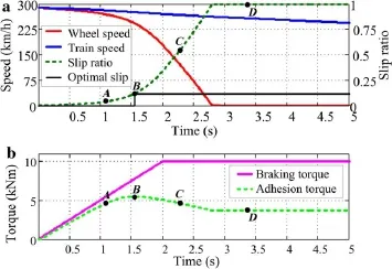
Fig.5 Result of optimal operation point searching
mayensuretherobustnessofthemodelinguncertainties.The SMC law is designed as

5 Results and analysis
5.1Simulation setup
A numerical simulation is conducted to verify the proposed methodology.We use a motor car of an EMU set using the parameters listed in Table 1.The motor car is propelled by fourindependentlydrivenwheelsetsactuatedbyfourelectric motors.The total fitte resistance is,where ν is
the train speed(km/h).In the simulation,the train brakes on straight fla rails actuated by the regenerative braking torques generated from the motors.The electric braking torqueincreasesuntilreachingitsmaximumlimit.Theinitial train speed and wheel speed are the same as 288 km/h.During braking,the controller does not know any information of the wheel-rail contact conditions,including the optimal slip ratio and the maximum friction coefficient

Table 1 Parameters of the EMU train in the simulation
5.2Results of the optimal slip ratio generation
In the simulation,a low grip wheel-rail contact condition is usedtorepresentslipperyrails,asshowninFig.1b(thesolid curve).The optimal slip ratio is around 0.12.Figure 5 shows the results of the optimal slip ratio determination.With the increasing braking torque,the operation point has the following four stages:(1)the stable adhesion(e.g.,point A), where the adhesion torque is increased with respect to time, i.e.,with positive slope;(2)the optimal point(B),where the adhesiontorquereachesthemaximumvalue;(3)theunstable skidding(e.g.,pointC),wheretheadhesiontorqueisreduced obviously,i.e.,withnegative slope;(4)the completely wheel locking(e.g.,point D),where the adhesion torque reaches the minimum value.It isclear the optimal point B that corresponds to the optimal slip ratio λ∗=0.12 can be determined dynamically using the proposed methodology in Sect.4.3. If the operation point is maintained at the optimal one,the maximum adhesion force is achieved.
5.3Results of the adhesion control for wheel slip prevention
Theproposedwheelslippreventioncontrolisevaluatedusing thelow-gripwheel-railcontactconditioninFig.1b,wherethe slip ratio reference is determined on line using the proposed methodpresentedinSect.4.3.Additionally,theconstantslip ratio references λ∗=0.05 and λ∗=0.25 are also used for comparison.Table 2 compares the performance in terms of the stop distance,the stop time,and the total energy that is transmitted from the car to the motors.Results indicate that the proposed control scheme has the shortest stop time and stop distance.The total energy for recovery is also high.
Inordertoinvestigatethestabilityandadaptabilityincomplex unknown wheel-rail conditions,a changing wheel-rail condition is further verifiein the simulation.The wheelrail adhesion curve changes from the mid-grip condition to thelow-gripconditionatthetimet=15s.Themid-gripand low-gripcurvescanbeseeninFig.1b,wheretheoptimalslip ratioofthemid-gripcurveisλ∗=0.175.Figure6showsthe results with the proposed regenerative braking control strategy.The operation point slides from point A to the optimal point B,andismaintainedaroundtheoptimalpointthereafter on the mid-grip rails.At the time t=15s,the rails change to low-grip rails.The operation point slides from point H to the optimal point I,and is maintained around the optimal point thereafter.The slip ratio is maintained around the optimal values of λ∗=0.175,and λ∗=0.12,respectively. It indicates that the proposed methodology is applicable to theunknownvaryingwheel-railcontactconditionsviadetermining the optimal slip ratio reference.

Table2 Performancecomparisonforregenerativebrakingonlow-grip rails

Fig.6 Results of regenerative braking on unknown slippery rails
6 Conclusion
This research analyzes the torque transmitting behavior during regenerative braking and proposes a novel wheel slip prevention control for the regenerative braking of high speed EMUtrains.Itisprovedthatthetorquetransmittingbehavior can indicate the wheel-adhesion stability during regenerative braking.Then,this research investigates the wheel slip prevention control for regenerative braking,and proposes a new optimal slip ratio controller,which can determine the optimal slip ratio reference via investigating the adhesion torque dynamically under the action of an increasing regenerative braking torque.The robust sliding mode controller is designed to track the slip ratio reference.Numerical simulation results indicate that the proposed methodology can determine the adhesion stability,search the optimal slipratio online,andachievetheoptimalslipratiocontrolunderuncertain wheel-rail conditions.The braking safety is ensured and the adhesion utilization is improved because the operation pointismaintainedarounditsoptimalonewithoutthewheelrail contact knowledge.
Thisresearchcontributestoexploringanewmethodology for the wheel-rail adhesion detection and control from the torque transmitting point of view for the high speed EMU trains.Futureresearchwillfocusonimprovingtherobustness under various disturbances and parameter perturbations and the experimental verificatioto improve its feasibility for practical use.AcknowledgmentsThis work was supported by the National NaturalScienceFoundationofChina(Grant51305437)and Guangdong Innovative Research Team Program of China(Grant 201001D0104648280).
References
1.Xu,F.,Shi,L.M.,Li,Y.H.:The weighted vector control of speedirrelevant dual induction motors fed by the single inverter.IEEE Trans.Power Electron.28,5665-5672(2013)
2.Bouscayrol,A.,Pietrzak-David,M.,Delarue,P.,et al.:Weighted control of traction drives with parallel-connected AC machines. IEEE Trans.Ind.Electron.53,1799-1806(2006)
3.Eom,B.G.,Kang,B.B.,Lee,H.S.,et al.:A study on running stability assessment methods for 1/5 small scaled bogie of saemaul usingsmall-scaledderailmentsimulator.Int.J.Precis.Eng.Manuf. 14,589-598(2013)
4.Dominguez,M.,Fernandez-Cardador,A.,Cucala,A.P.,et al.: Energy savings in metropolitan railway substations through regenerative energy recovery and optimal design of ATO speed profiles IEEE Trans.Autom.Sci.Eng.9,496-504(2012)
5.Ragavan,S.V.,Kumar,J.M.,Ponnambalam,S.G.:Design of a mechatronic drive train with regenerative braking.Mech.Aerosp. Eng.Pts 1,5111-5117(2012)
6.Teramoto,K.,Ohishi,K.,Makishima,S.,etal:Cooperativecontrol of regenerative brake and mechanical brake for a two coach train. In:Proceedings of the 38th Annual Conference on IEEE Industrial Electronics Society(Iecon 2012),1707-1712(2012)
7.Yin,G.D.,Jin,X.J.:Cooperative control of regenerative braking and antilock braking for a hybrid electric vehicle.Math.Probl. Eng.,1-9(2013)
8.Park,D.Y.,Kim,M.S.,et al.:Hybrid re-adhesion control method for traction system of high-speed railway.In:Proceedings of the 5th International Conference on Electrical Machines and Systems, Vols I and II,739-742(2001)
9.Shirai,S.:Adhesion phenomena at high-speed range and performance of an improved slip-dectector.Q.Rep.Railw.Tech.Res. Inst.18,189-190(1977)
10.Park,S.H.,Kim,J.S.,Choi,J.J.,et al.Modeling and control of adhesion force in railway rolling stockss.IEEE Control Syst.Mag. 28,44-58(2008)
11.Zuo,J.Y.,Chen,Z.K.:Antiskid control of railway train braking based on adhesion creep behavior.Chin.J.Mech.Eng.25,543-549(2012)
12.Watanabe,T.,Yamashita,M.:Basic study of anti-slip control without speed sensor for multiple motor drive of electric railway vehicles.Proc.Power Conver.Conf.3,1026-1032(2002)
13.Ohishi,K.,Ogawa,Y.,Miyashita,I.,et al.:AntiSlip re-adhesion control of electric motor coach based on force control using disturbance observer.Ind.Appl.Conf.2,1001-1007(2000)
14.Takaoka,Y.,Kawamura,A.:Disturbance observer based adhesion control for shinkansen.In:Proceedings of Advanced Motion Control 6th International Workshop,69-174(2000)
15.Kawamura,A.,Furuya,T.,Takeuchi,K.,etal:Maximum adhesion control for shinkansen using the tractive force tester.In:Proceedings of IEEE 28th Annual Conference of the Industrial Electrics Society 1,567-572(2002)
16.Ishikawa,Y.,Kawamura,A.:Maximum adhesion force control in super high speed train.Proc.Power Conver.Conf.2,951-954 (1997)
17.Cheok,A.D.,Shiomi,S.:A fuzzy logic based anti-skid control system for railway application.Knowledge-Based Intell.Electron. Syst.1,195-201(1998)
18.Park,S.H.,Kim,J.S.,Choi,J.J.:Reference slip ratio generation and adaptive sliding mode control for railway rolling stocks.Int.J. Precis.Eng.Manuf.10,39-44(2009)
19.Ohishi,K.,Nakano,K.,Miyashita,I.,et al.:Anti slip control of electric motor coach based on disturbance observer.The 5th IEEE International Workshop on Advanced Motion Control,580-585 (1998)
20.Watanabe,T.,Yamashita,M.:A novel anti-slip control without speed sensor for electric railway vehicles.In:Proceedings of the 27thAnnualConferenceoftheIEEEIndustrialElectronicsSociety, 1382-1387(2001)
21.Wang,H.,Xiao,J.:Astudyonfuzzycontroloflocomotiveoptimal adhesion.AMSE Periodicals Model.B 72,57-71(2003)
22.Xu,K.,Xu,G.Q.,Zheng,C.H.,et al:A novel adhesion stability detection methodology and slip prevention control strategies for wheeledgroundvehicles.In:ProceedingsoftheIEEEInternational Conference on Robotics and Biomimetics,76-81(2014)
23.Wickens,A.H.:FundamentalsofRailVehicleDynamics:Guidance and Stability.Swets&Zeitlinger Publisher,Amsterdam(2003)
24.Yamazaki,H.,Nagai,M.,Kamada,T.:A Study of adhesion force model for wheel slip prevention control.JSME Int.J.Series C 47, 496-501(2004)
25.Xu,K.,Xu,G.Q.,Zheng,C.H.:Novel determination of wheelrail adhesion stability for electric locomotives.Int.J.Precis.Eng. Manuf.16,56-63(2015)
26.Shimizu,Y.,Kadowaki,S.,Ohishi,K.,et al.:Evaluation and discussion of disturbance observer-based anti-slip/skip re-adhesion control for electric train.Electr.Eng.Jpn.169,55-64(2009)
26 November 2014/Revised:13 January 2015/Accepted:26 July 2015/Published online:8 March 2016
✉Guo-Qing Xu xugq1967@126.com;gq.xu@siat.ac.cn
1Shenzhen Institutes of Advanced Technology,Chinese Academy of Sciences,and The Chinese University of Hong Kong,Shenzhen 518055,China
2Shenzhen College of Advanced Technology,University of Chinese Academy of Sciences,Shenzhen 518055,China3School of Electronics and Information,Tongji University, Shanghai 201804,China
杂志排行
Acta Mechanica Sinica的其它文章
- Correcting the initialization of models with fractional derivatives via history-dependent conditions
- Tomographic PIV investigation on coherent vortex structures over shark-skin-inspired drag-reducing riblets
- Analysis of the geometrical dependence of auxetic behavior in reentrant structures by finit elements
- The equilibrium stability for a smooth and discontinuous oscillator with dry friction
- Impact toughness of a gradient hardened layer of Cr5Mo1V steel treated by laser shock peening
- Why a mosquito leg possesses superior load-bearing capacity on water:Experimentals
