Aerodynamic design on high-speed trains
2016-09-06SanSanDingQiangLiAiQinTianJianDuJiaLiLiu
San-San Ding·Qiang Li·Ai-Qin Tian·Jian Du·Jia-Li Liu
Aerodynamic design on high-speed trains
San-San Ding1,2·Qiang Li1·Ai-Qin Tian2·Jian Du2·Jia-Li Liu2
©The Chinese Society of Theoretical and Applied Mechanics;Institute of Mechanics,Chinese Academy of Sciences and Springer-Verlag Berlin Heidelberg 2016
AbstractCompared with the traditional train,the operationalspeedofthehigh-speedtrainhaslargelyimproved,and thedynamicenvironmentofthetrainhaschangedfromoneof mechanical domination to one of aerodynamic domination. Theaerodynamicproblemhasbecomethekeytechnological challenge of high-speed trains and significantl affects the economy,environment,safety,and comfort.In this paper, the relationships among the aerodynamic design principle, aerodynamic performance indexes,and design variables are firs studied,and the researchmethods of trainaerodynamics are proposed,including numerical simulation,a reducedscale test,and a full-scale test.Technological schemes of train aerodynamics involve the optimization design of the streamlined head and the smooth design of the body surface.Optimization design of the streamlined head includes conceptiondesign,projectdesign,numericalsimulation,and a reduced-scale test.Smooth design of the body surface is mainly used for the key parts,such as electric-current collecting system,wheel truck compartment,and windshield. The aerodynamic design method established in this paper has been successfully applied to various high-speed trains (CRH380A,CRH380AM,CRH6,CRH2G,andtheStandard electric multiple unit(EMU))that have met expected design objectives.The research results can provide an effective guideline for the aerodynamic design of high-speed trains.
KeywordsHigh-speed train·Aerodynamic design· Optimization design·Smooth design
1 Introduction
High-speed rail is a common trend in the development of world rail transportation,and it is also the main indicator of the modernization of railway technology.In recent years,high-speed rail has attracted considerable attention and rapid development all over the world.In China,it has been the subject of research and has been under construction.Until now,the number of high-speed railway lines is 54,and the total mileage of high-speed rails is 18000km, which accounts for 60%of the total mileage in the world. High-speed trains,which constitute the core of high-speed railway,are represented by 23 versions in China,including common electric multiple units(EMUs),cold-weather EMUs,intercity EMUs,comprehensive inspection EMUs, and sleeping-berth EMUs,and the operational speed ranges from 200 to 400km/h.The main versions of the high-speed traininChinaaretheCRH380AandCRH380B,withamaximum operational speed of 380km/h.
With the increasing train speeds,the interaction between a high-speed train and the ambient air becomes increasingly obvious,and the dynamic environment of the train changes from one of mechanical domination to one of aerodynamic domination.The aerodynamic problem has become the key technological challenge of high-speed trains[1-3].When a high-speed train’s speed reaches 205-300km/h near the ground in the atmosphere,the resistance of the train mainly comes from the ambient air,and the aerodynamic drag could accountfor75%ofthetotalresistance[4].Theaerodynamicdrag is proportional to the second order of the train speed, and it will take a greater proportion of the total resistance at a higher train speed.The aerodynamic drag becomes one of the main factors in restraining the train speed and in energy conservation.The reduction of the aerodynamic drag plays a very important role in the aerodynamic design of high-speed trains.Moreover,other aerodynamic forces(moments)are also proportional to the second order of the train speed.The aerodynamic forces(moments)increase quickly with train speed,which may lead to the deterioration of the operational safety of high-speed trains.
For example,the upward lift force may reduce the wheelrailcontactforceandcreatesafetyissues[5].Inparticular,the flw fiel of a high-speed train undergoes obvious changes in strong crosswinds,and the aerodynamic side force,lift force,rollmoment,andsoforthdramaticallyincrease,which greatly influence the operational safety of the train[6-9]. The pressure on the train surface could change rapidly when the train is traveling at a high speed in the atmosphere,especially in connection with oncoming trains or trains going through a tunnel.The transient pressure impulse may have significan effects on the strength of car bodies and windows.Reducing the pressure wave of trains passing each other or a train going through a tunnel,as well as improving the air-tightness strength,is very important in the aerodynamic design of high-speed trains[10-12].Aerodynamic noise is also an important problem caused by increases in train speed.When train speed reaches 300km/h,the aerodynamic noise will drown out the wheel/rail noise.This poses a great challenge in terms of reducing the aerodynamicnoiseofhigh-speedtrains[13-15].Thus,aerodynamic design should be carried out for high-speed trains,which is rarely a consideration for traditional trains.There are many objectives in the aerodynamic design of high-speed trains,such as,for example,aerodynamic drag,lift force of the tail car,aerodynamic performance under side winds, pressure wave of trains passing each other or trains going through a tunnel,and aerodynamic noise.The design objectives are usually opposed to each other;the ultimate goal of the aerodynamic design of high-speed trains is to coordinate the compromises and tradeoffs between various design objectives and optimize each of the objectives as far as possible[16].
Theaerodynamicissuesassociatedwithhigh-speedtrains are always emphasized in China during their research and development.To obtain the optimal shape of high-speed trains,much research work on train aerodynamics is carried out.Meanwhile,a series of streamlined head shapes of high-speed trains with typical characteristics and smooth schemes of the body surface are obtained.On this basis,the main purpose of the present paper is to establish a complete and systematic aerodynamic design method for high-speed trains.
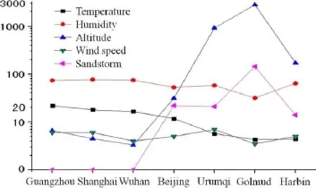
Fig.1 Environmental characteristics of typical cities
2 Research topics related to train aerodynamics
At present,the largest network of high-speed railways is in China,which accounts for 60%of the total length of highspeed railway worldwide.The operational environment of high-speed railway is very complex.The four longitudinal andfourhorizontalpassengerspeciallinesandthreeintercity passenger systems proposed in the national middle-/longterm transport plans cover different terrains,such as,for example,plains,mountainous,hills,and plateaus.The temperature,humidity,altitude,wind speed,and the presence or absence of sandstorms in different cities along the railway are very different,which can be seen in Fig.1.The railway system in China is very complex and comprises high-speed railway,intercity railway,fast railway,and conventional railway,on both ballast and ballastless track at the same time.There are also many embankments,viaducts,and tunnelsalongrailwaylines.Forthehigh-speed-trainsections, high-speed trains have a large slenderness ratio and run on track near the ground,which could lead to more obvious aerodynamic problems compared with other means of transportation.The clearance between a high-speed train and the ground is small,and the influenc of the ground effect is verysignificant Ahigh-speedtrainconsistsofmanydifferent cars,and a car has many complex parts,such as the pantograph,wheel truck,and windshield.Thus,the body shape of a high-speed train has multiscale characteristics and the flw fiel around the train is very complex.In addition,natural winds,trains passing each other,or trains going through tunnels usually occur when high-speed trains are running on tracks,which leads to very complex aerodynamic problems. Compared with traditional trains,the operational speed of high-speed trains has improved considerably,and the influ ence of aerodynamic effect has changed qualitatively,which has raised many aerodynamic challenges.With increasing trainspeeds,aerodynamicdragbecomesthemainresistance. Thetractionpoweroftrainsshouldbeenhancedtoovercome aerodynamic drag.Aerodynamic noise is also an importantproblem caused by increases in train speed.Aerodynamic noise is an environmental hazard and could also radiate into the interior of trains,leading to passenger discomfort.The aerodynamic forces(moments)of high-speed trains caused by natural winds have a great influenc on the operational safety of high-speed trains,and pressure waves caused by trains passing each other or trains going through tunnels significantl influenc the performance of high-speed trains.In general,the aerodynamic problems significantlinfluenc the economic,environmental,safety,and comfort performanceofhigh-speedtrains,whichareresearchtopicsrelated to train aerodynamics.
2.1Economic performance
For high-speed trains running in the dense atmosphere near the ground,the running resistance of the train consists of the mechanical resistance,air momentum loss resistance,and aerodynamicdrag.Themechanicalresistanceisproportional to the mass of the train,which is unrelated to train speed. Air momentum loss resistance is proportional to train speed. Aerodynamic drag is proportional to the square of the train speed.Thus,the proportion of aerodynamic drag increases most rapidly with increasing train speed.When the train speed exceeds 200km/h,or especially reaches 300km/h, the resistance of a high-speed train is mainly caused by the ambient air.The increase in the running resistance of a high-speed train enhances the requirements of traction power.Figure 2 shows the required traction power of a train per ton at different train speeds.It can be seen from Fig.2 that the required traction power quickly increases with train speed.The increased traction power is mainly used to overcome aerodynamic drag,which leads to an increase in the operational energy consumption.To improve the economic performanceofhigh-speedtrains,dragreductionhasbecome the major problem in their design.A deep understanding of the resistance characteristics of high-speed trains and a drag reduction method that could reduce the operational energy consumption of such trains have practical engineering significance
Intheopenairwithzerowindspeed,therunningresistance of a train at a constant speed can be expressed as[17]
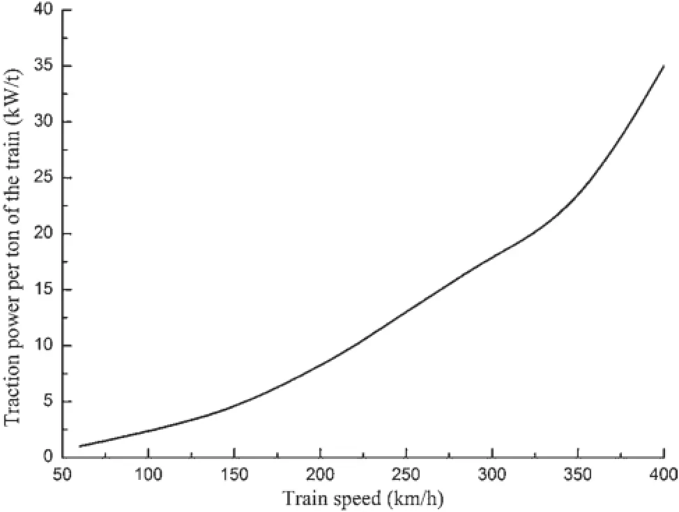
Fig.2 Traction power for different train speeds
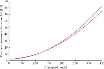
Fig.3 Resistance assessment by casting test

where C1,C2,C3are constants for a particular train that can be determined by experiment;vtris the train speed;C1is the rollingmechanicalresistance;C2vtristheairmomentumloss resistance;C2=ρQ,Q is the total air volume flw;C3v2tris the aerodynamic drag,which consists of the pressure drag force and skin friction drag force.
Figure3showsaresistanceassessmentbyacastingtestfor twotypicalhigh-speedtrains.Fromthecastingtestresultswe can obtain the coefficient C1,C2,and C3in Eq.(1)for each high-speed train.Then the proportion of these three kinds of resistance in the total resistance for different train speeds can be computed.Our analysis revealed that when the train speed reaches 350km/h,the proportion of the mechanical resistance in the total resistance is less than 5%,and the proportion of the air momentum loss resistance in the total resistance is approximately 10%.Therefore,the proportion of the aerodynamic drag in the total resistance is more than 85%.The key in drag reduction in high-speed trains is to reduce the aerodynamic drag.
There are three ways to reduce the aerodynamic drag of a high-speed train:(1)optimize the design of the streamlined head:aerodynamic drag can be reduced by,for example,increasing the slenderness ratio,decreasing the crosssectional area,or optimizing the contour line;(2)design a smoothtrainbodysurface:aerodynamicdragcanbereduced by smoothing the key parts of the train body,such as the pantograph,wheel truck,and windshield areas;(3)use flwcontroltechnology:aerodynamicdragcanbefurtherreduced using active/passive flw control technology,such as bionic design or turbulence control.However,this technology has not yet been applied to high-speed trains.
2.2Environmental performance
Noise has become the biggest challenge and limitation since aerodynamic effects came to dominate the dynamic environment of high-speed trains.According to theoretical research and test results on railway noise in China and in other countries,train noise mainly consists of propulsion noise, wheel/rail noise,and aerodynamic noise,and the relation between noise and train speed is shown in Fig.4.The contribution of these three kinds of noise to the total noise is related to train speed.At lower speeds,the greatest contribution to total noise is the propulsion noise.As the train speed increases,the wheel/rail noise exceeds the propulsion noise and becomes the main noise of the train.With further increases in train speed,aerodynamic noise is the greatest contributor to total noise.Therefore,two critical speeds emerge,shownas VC1and VC2inFig.4,define asthesound transformation speed.When the wheel/rail noise iswell controlled,VC1becomes large and VC2becomes small.
Research results show that when a train’s speed reaches 300km/h,the aerodynamic noise will exceed the wheel/rail noise and thus become the main noise of the train[18]. Aerodynamic noise has a significan effect on the environment.Excessive environmental noise pollution has become the key factor restricting increases in train speed.Regions through which high-speed trains pass usually contain dense populations,which impose strict requirements regarding environmental noise.High-speed trains must be designed in such a way as to determine the maximum speeds in different regions surrounding track in accordance with the requirements of environmental protection.To this end,the characteristics of the aerodynamic noise of high-speed trains and noise reduction methods should be studied in depth.
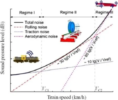
Fig.4 Train noises and their relationship with train speed
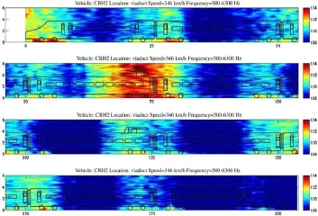
Fig.5 Distribution of noise sources
Figure 5 shows the distribution of noise sources for a typical high-speed train.The figurshows that the noise is distributed mainly in the pantograph system,wheel/rail contact area,streamlined head,and intercoach spacing.The noise of the wheel/rail contact area consists of wheel/rail noiseandaerodynamicnoisefromthewheeltruck.Thenoise in the pantograph system is mainly aerodynamic noise.In practice,the pantograph system is composed of many bars with small diameters,which can create a number of vortices behinditandgenerateaerodynamicnoise[19].Thenoisesof the streamlined head and intercoach spacing are also mainly aerodynamic noise.
The micro-pressure waves generated by trains going through tunnels also represent an important problem affecting the environment[20].When the streamlined head of a trainentersatunnel,acompressionwaveisgenerated,which propagates through the tunnel at the speed of sound.When it encounters the open end of the tunnel,the majority of this head wave is reflecte as a rarefaction wave by the boundary conditions of the open end and propagates back toward the entry portal.A smaller part of the head wave exits the tunnel and radiates outside in the form of an impulselike micropressure wave(Fig.6).At the same time,the micro-pressure wave can create a booming noise and may lead to the rattling of structures like windows and doors and cause noise pollution at the tunnel exit.
The micro-pressure wave is in proportion to the pressure gradientattheexitportal.Dependingontheinitialgradientof the compression wave at the entry portal and the presence or absence of modern concrete slabtrack,which generates only slight dissipation of the propagating wave,steepening may lead to much greater gradients at the exit portal.In ballasted track tunnels,the gradient at the exit portal is lower than that at the entry portal.
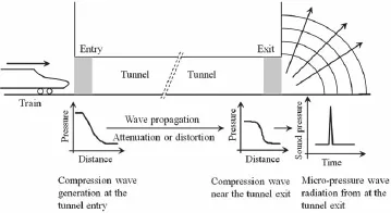
Fig.6 Wave generation,propagation,and radiation in high-speed train/tunnel system
2.3Safety performance
The aerodynamic effect of high-speed trains can cause many safety issues,including the crosswind effect and problems related to the operational safety of high-speed trains,the lift force of the tail vehicle and its operational safety,the transient pressure impulse,and the strength of the train body andoperationalsafety,train-inducedwinds,andthesafetyof equipment along the track and passengers on the platform.
The issue regarding the stability of high-speed trains in strong crosswinds has been the subject of innumerable studies[21,22].In strong crosswinds,the flw fielaround high-speed trains has obviously changed.Figure 7 shows streamlines at different cross sections for a high-speed train subject to strong crosswinds.It can be seen from Fig.7 that a number of vortices are generated at the leeward side of the high-speed train,leading to a sharp increase in aerodynamic side force,lift force,and rolling moment.Figure 8 shows the aerodynamic side force coefficien and lift force coefficien for a high-speed train at different yaw angles.As shown in Fig.8,theaerodynamiccoefficient quicklyincreasewiththe increasing yaw angle.The increase in aerodynamic forces (moments)has a large influenc on the lateral stability of high-speed trains,which may lead to the derailment or overturning of a train.
The streamlined head of a high-speed train can reduce the aerodynamic drag and aerodynamic noise.However,a number of vortices are generated behind the streamlined head of thetailvehicle,whichisshowninFig.9.Thevorticesbehind the tail vehicle can cause a large lift force in the tail vehicle, which will significantl affect the operational safety of the tailvehicle.Asfortheoptimizationdesignofthestreamlined head of a high-speed train,the lift force of the tail vehicle requires particular attention in order to improve the operational safety of the tail vehicle.
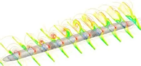
Fig.7 Streamlines at different cross sections
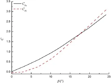
Fig.8 Aerodynamic coefficient at different yaw angles
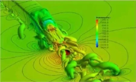
Fig.9 Vorticity behind tail vehicle
Atransientpressurewaveonthetrainsurfaceisgenerated when trains are passing each other or a train goes through a tunnel.Excessive transient pressure impulses significantl affect the strength of train bodies and the operational safety of a high-speed train.To explore transient pressure waves under conditions observed in China’s railway system and grasptheirchangerule,aseriesoffull-scaletestsandnumerical simulations were carried out,and the strength standard of high-speed trains at a speed of 350km/h is set.The full-scale test of trains passing each in the tunnel of the Wuhan-Guangzhouhigh-speedrailwayshowsthatthemaximum amplitude of a transient compression wave on the train surface is 5714 Pa,and Fig.10 shows the corresponding numerical simulation of the strength of the train body with a standard of±4kPa.As shown in Fig.10,the maximum stress exceeds 38 MPa,which is too close to the limit value. The full-scale test also shows that the deformation of a trainbodyislarge.Accordingtotheresearchresultsofafull-scale testandnumericalsimulation,whenthetrainspeedincreases from 250 to 350km/h,the strength standard of the train body should be enhanced,and the strength standard is improved from±4 to±6kPa.
The winds induced by high-speed trains have an aerodynamic effect on passengers on the platform and objects surrounding the railway line and further affect their security. The aerodynamic forces on the passengers and objects are caused by train-induced winds.The magnitudes and directionsoftheseforceschangeasatrainpasses,andtheirvalues depend on the train speed,the size and shape of the train,the distancebetweentheobjectconcernedtothesideofthetrain, and the size and shape of the object.
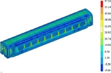
Fig.10 Strength simulation of train body for train speed of 350 km/h and strength standard of 4kPa
2.4Comfort performance
The aerodynamic effect of high-speed trains can also cause many problems related to comfort,which involve transient pressure impulses on the train surface and the interior pressure fluctuatio of the train,the fluctuatin pressure on the train surface,and the interior noise of the train.
Transient pressure fluctuation on a train surface are generated when trains pass each other or a train goes through a tunnel.The transient pressure can be transmitted toward passenger compartments and seriously affect the comfort of passengers.The train body of modern high-speed trains has good sealing performance,which can mitigate the effects of airpressurechanges.Thus,themagnitudeoftheinteriorpressureislessthanthatoftheexteriorpressure.Figure11shows the time histories of exterior pressure,interior pressure,and pressure difference when a high-speed train goes through a tunnel.As shown in Fig.11,the interior pressure undergoes obvious changes.For the design of a high-speed train body, the sealing performance of the train should be improved to reduce the influenc of the exterior pressure on the interior pressure.
Moreover,as the train speed picks up speed,the fluctu ating pressure on the train surface becomes more and more significant Thefluctuatin pressureistransmittedtowardthe passenger compartment through the walls and holes of the train and generates interior noise,which significantl affects passenger comfort.
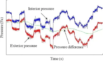
Fig.11 Time histories of transient pressure of a train going through a tunnel
3 Methods of researching train aerodynamics
3.1Research outlines
Because the aerodynamic performance of a high-speed train involves many aspects,the corresponding problem between aerodynamic performance indexes and design variables should be solved,and the restrictions of spatial structures on the train shape need to be considered.Meanwhile,the requirements of national cultural traditions also need to be takenintoaccount.Themethodsofresearchingtrainaerodynamics mainly involve numerical simulations,reduced-scale testing,and full-scale testing.Researching the aerodynamic designofhigh-speedtrainsinvolvesanalyzingthecorrelation between aerodynamic performance indexes and design variables and optimizing the design of the train’s shape based on numerical simulations and reduced-scale testing under certain restrictions.Figure 12 shows the relationships among the aerodynamic design principle,performance indexes,and design variables.
Theaerodynamicdesignprincipleincludeseconomicperformance,environmental performance,safety performance, and comfort performance.The main performance indexes include surface pressure,aerodynamic drag,lift force of the tail vehicle,pressure wave of trains passing each other, aerodynamic noise,train-induced winds,aerodynamic performance due to crosswinds,pressure variations in tunnels,micropressure wave,and others.The main design variables include the cross-sectional shape of the train body,the maximum cross-sectional area of the train body,the slenderness ratio,the ratio of change to the cross-sectional area,the longitudinal-sectional shape,the horizontal-sectional shape, thestreamguidanceoftrainnose,thesideshieldofthewheel truck,the inclination of the drive chamber,and the surface smoothness.Therelationshipsbetweentheaerodynamicperformance indexes and design variables are very complex. In most cases,the aerodynamic performance indexes are opposedtoeachother,anditisnotpossibleforseveralobjectives to achieve the optimal solution at the same time.The aerodynamic design of high-speed trains belongs to the category of multiobjective optimization.
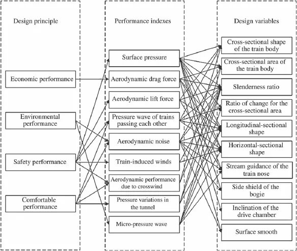
Fig.12 Aerodynamic design principle,performance indexes,and design variables
3.2Numerical simulation
The numerical simulation of train aerodynamics belongs to the category of computational flui dynamics(CFD),which involves solving the governing equations describing flui flw using a numerical computational method and obtaining flw fiel information.The numerical simulation could take into account various aerodynamic problems,understand the mechanism of each flw phenomenon in depth,and obtain quantitative results.With the rapid development of computational technology and high-performance computers,the numerical simulation has became an important method in the research of train aerodynamics.
3.2.1Governing equations
Proper selection of the governing equations describing the flw fiel of a high-speed train is the key to numerical simulation.The governing equations of the flw fielare the Navier-Stokes equations.Theoretically,any fluiis compressible.However,when the influencof the change in fluidensity on flw is negligible,the fluican be considered incompressible,which means that the flui density is constant.For high-speed trains running on open track, their operational Mach number is small(when the train speed is 400km/h,the Mach number is 0.3268),the air around the trains can be considered incompressible,and the corresponding governing equations are three-dimensional incompressible Navier-Stokes equations.But the compressibility of the air should be considered for trains passing each other or going through tunnels,and the correspondinggoverning equations are the three-dimensional compressible Navier-Stokes equations.
The flw around a high-speed train is complex turbulence flw,whichisusuallycharacterizedbythefollowingaspects: separation,possible reattachment,recirculation and swirling properties,and a curved boundary.Simulating turbulence is the key to numerical simulation.At present,the main approaches to turbulence simulation involve,for example, Reynolds averaged Navier-Stokes(RANS),large eddy simulation(LES),and detached eddy simulation(DES).RANS is the main method for engineering turbulence computations and is widely used in the simulation of various aerodynamic problems.However,forthesimulationofaerodynamicnoise, sufficientl accurate fluctuatin pressure on the train surface should be simulated,and currently,the RANS usually no longerappliesandtheLESisusedtoobtainsufficientl accurate flw fiel information.
3.2.2Numerical model
In general,a high-speed train should have at least three vehicles(headvehicle,middlevehicle,andtailvehicle).Withthe development of high-performance computers,the numerical simulation of train aerodynamics for high-speed trains with eightvehiclescanbecarriedout.Figure13showsageometric model of the new generation of high-speed trains CRH380A with eight vehicles;the model has the main parts of a highspeed train,such as,for example,pantograph,wheel truck, and windshield.
The mesh division and mesh quality have a direct impact on computational accuracy and stability.A large mesh size can be used for the whole computational region,and a small mesh size should be used for local regions where the flw changes quickly with time,including the region around the train body,the wake flw region,wheel truck region, and pantograph region.The mesh must meet basic requirementsconcerningwallunitsadjacenttono-slipwalls.Typical values for the dimensionless wall distance y+for RANS simulations are 30~150 for the high-Reynolds-number turbulence model.As for the LES,the grid density near walls should be fin enough to resolve the small-scale structures that arise via shear layer instabilities.The distribution of spatial grids for the CRH380A is shown in Fig.14.Following mesh division,the boundary condition should be set up according to actual conditions.

Fig.13 Geometric model of high-speed train
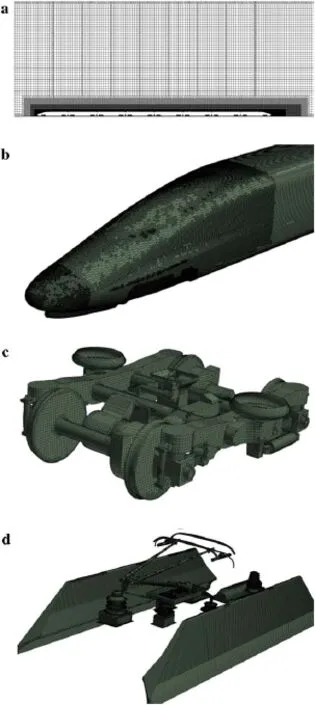
Fig.14 Distributionofspatialgrids.aGridsforlongitudinalsymmetry plane.b Grids for streamlined head.c Grids for wheel truck.d Grids for pantograph
3.2.3Moving train
As for trains passing each other or going through a tunnel, they move during the computation process.Therefore,the simulation for a moving train should be achieved.In the present paper,the sliding mesh and dynamic layering methods are used.
For the sliding mesh method,the zones for stationary and moving components are divided.The sliding mesh model allows adjacent grids to slide relative to one another.Thus,the grid faces do not need to be aligned on the grid interface. This situation requires a means of computing the flu across the two nonconformal interface zones of each grid interface.
To compute the interface flux the intersection between the interface zone is determined at each new time step.The resultingintersectionproducesoneinteriorzone(azonewith fluicells on both sides)and one or more periodic zones. If the problem is not periodic,such as trains passing each other or going through a tunnel,the intersection produces one interior zone and a pair of wall zones.To avoid this, the dynamic layering method is used for this situation and a periodic zone is generated(Fig.15).
The mesh updating principle of the dynamic layering method is shown in Fig.16.The layer of cells adjacent to the moving boundary(layer j in Fig.16)is split or merged with the layer of cells next to it(layer i in Fig.16)based on the height(h)of cells in layer j.
If the cells in layer j are expanding,they can be expanded until
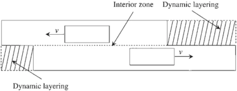
Fig.15 Sliding mesh and dynamic layering method for trains passing each other
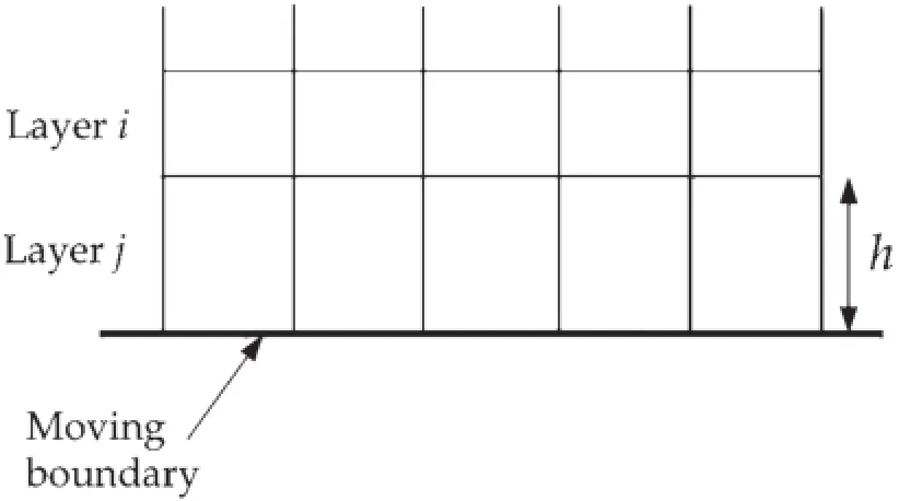
Fig.16 Mesh updating principle

where hminis the minimum cell height of cell layer j,hidealis the ideal cell height,and αsis the layer split factor.When this situation is encountered,the cells of layer j are split into a layer of cells with constant height hidealand a layer of cells of height h−hideal.
If the cells in layer j are being compressed,they can be compressed until

where αcis the layer collapse factor.When this situation is encountered,the cells in layer j are merged with those in layer i.
3.3Reduced-scale test
3.3.1Flow similarity principle
Reduced-scale testing of train aerodynamics includes a wind tunnel test and a moving model test.For the wind tunnel test, the train model is assumed to be stationary,and air is blown through the train model to simulate the flw fiel of a highspeed train and test its aerodynamic performance.For the moving model test,an ejection mechanism is used to make thetrainmodelmovewiththetrainspeedtosimulatetheflw fiel of the train and test its aerodynamic performance.
A reduced-scale test is based on the flw similarity principle.If the train model used for the reduced-scale test and a realtrainaregeometricallysimilarity,andthetrainmodeland the real train have the same Reynolds number,Mach number,and so forth,the flw around the train model and the real train is also similar.As the medium for the reduced-scale test is air,the Mach number of the train model is the same as that of the real train,which means that the train model and therealtrainhavethesameoperational speed.Therefore,the flw similarity principle for the reduced-scale test is mainly the similarity of the Reynolds number,which means that the train model and the real train should have the same Reynolds number.Asthescalecoefficien issmall(ingeneral,1:8fora wind tunnel test and 1:20 for a moving model test),the operationalspeedofthetrainmodelshouldbethemultipleofthat of the real train in order to make it similar to the Reynolds number,which is very difficul to achieve.Research results show that the flw around a train has a self-similarity region; when the Reynolds number reaches 106,the Reynolds number has little effect on the aerodynamic performance of a high-speed train.Thus,when the train model and a real train access the self-similarity region,the Reynolds number for the train model and the real train do not have to be equal;the test results of the train model can be applied to the real train directly.
3.3.2Wind tunnel test
In the wind tunnel test,objects such as the train and the ground configuratio are manufactured in the reduced-scale models based on the geometric similarity,and the reducedscale models are fi ed on the test section of the wind tunnel. The wind tunnel can generate uniform air flw with the required velocity,density,and pressure.When the air flw blowsthroughthetrainmodel,theaerodynamicperformance of the train model can be tested under certain similarity con-ditions,which can reflec the aerodynamic performance of a real train[23,24].

Fig.17 Wind tunnel test for force and pressure measurement
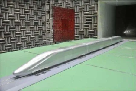
Fig.18 Wind tunnel test for aerodynamic noise
Aregularwindtunneltestmainlyincludesforceandpressuremeasurements(Fig.17).Theforcemeasurementismade to measure the aerodynamic drag force,lift force,side force, roll moment,yaw moment,and pitch moment by the sixcomponentforcebalancefordifferentgroundconfigurations inflw velocities,and yaw angles.Then the dimensionless aerodynamic coefficientat different yaw angles can be obtained.The pressure measurement is made to measure the pressureonthemainpartsofthetrain,suchasthestreamlined head,pantograph,wheel truck,and windshield.
In a special low-noise wind tunnel,the wind tunnel test for aerodynamic noise can be carried out to measure the aerodynamic noise sources on the train surface and farfielaerodynamic noise.Aerodynamic noise sources are measured using a microphone array,and the far-fiel aerodynamic noise is measured by a free-fielmicrophone. Figure 18 shows the train model and microphone array of a wind tunnel test for aerodynamic noise.The microphone array is set at the left of the train model and the free-fiel microphones are set at the right of the train model;thus, the aerodynamic noise source and the far-fiel aerodynamic noise can be measured at the same time.
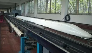
Fig.19 Moving model test for train going through a tunnel
3.3.3Moving model test
In the moving model test,objects such as the train,ground configuration and tunnel are manufactured in reduced-scale models based on geometric similarities,and an ejection mechanismisusedtomakethetrainmodelmoveatthetrain’s speed.Themovingmodeltestcansimulateatrainrunningon open track or going through a tunnel,and two trains passing eachotheronopentrackorinatunnel.Thetransientpressure variation on the train surface and the micropressure wave at the tunnel exit can also be measured by the moving model test.Figure 19 shows the moving model test for a train going through a tunnel.
Transient pressure fluctuation on the train surface are generatedwhentrainspasseachotherorgothroughatunnel. Thus the pressure sensor should have a fast enough response speed.Each pressure signal channel has an independent circuit structure and A/D converter.The same time code is used to control synchronous sampling to ensure that all channel data are consistent over time.
3.4Full-scale test
A full-scale test of train aerodynamics is carried out to measure the aerodynamic performance of a real train running on a railway line.The main test content of a full-scale test is the dynamic pressure of the train,including exterior and interiorpressure.Thedynamicpressuremeasurementsystem of a full-scale test consists of a pressure sensor,multichannelamplifie,A/Dconverter,computer,andanalysissoftware (Fig.20).Thissystemplacesthecomputerinthecenter,integratesmanyfunctionsofvariousvirtualinstrumentsusingthe software,carries out real-time measurement of many transient pressure signals,and quickly performs signal analysisand processing.Figure 21 shows the distribution of the pressure taps on the streamlined head of a high-speed train.
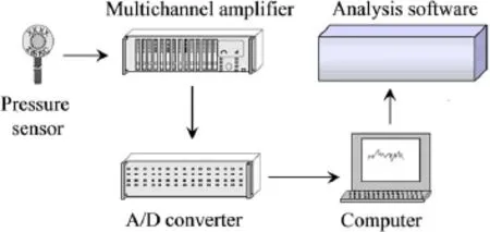
Fig.20 Dynamic pressure measurement system
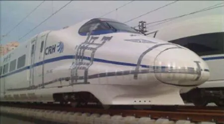
Fig.21 Distribution of pressure taps on streamlined head
4 Technological schemes of train aerodynamics
4.1Design scheme of streamlined head
4.1.1Conception design
In the conception design process,typical streamlined heads at home and abroad are studied,which involve,for example,the technological factor,cultural identity,national and regional characteristics,human-machine engineering,and bionics design,in order to capture the mainstream of the culturalandaestheticdesignofthestreamlinedheadandprovide inspirationfortheconceptiondesignofthestreamlinedhead. On the basis of a technology summarization and cultural analysis,various kinds of streamlined heads with different technological and cultural characteristics have been designed,as shown in Fig.22.
4.1.2Project design
On the basis of the conception design,the preliminary selection of streamlined heads is performed from the standpoint ofaerodynamicsandindustrialdesign.Meanwhile,apreliminary technological analysis of the streamlined head should be carried out,including,for example,the manufacturing process,structural strength,and part relationships.Then suggestions for improvement should be proposed to modify the initial design schemes.1:20 models of preferred streamlined heads are manufactured to perform an intuitive selection of each scheme.By the compromises and tradeoffs betweentechnologicalperformanceandculturalcharacteristics,seven preferred streamlined heads are further developed whose aerodynamic performance will be analyzed in detail bynumericalsimulationandreduced-scaletesting.Figure23 shows the cross-sectional areas of these seven streamlined heads.
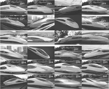
Fig.22 Conception design of streamlined head
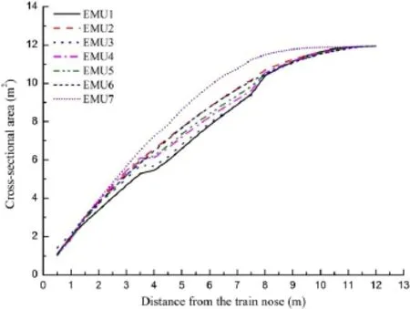
Fig.23 Cross-sectional area of streamlined head
4.1.3Numerical simulation analysis
A numerical simulation method is used to obtain all aerodynamic performance indices of a high-speed train,including the train running on the open track with zero wind(toobtain the basic aerodynamic drag and lift force),the train under strong winds(to obtain the aerodynamic coefficient at differer yaw angles),trains passing each other on open track(to obtain the pressure wave,aerodynamic forces,and moments),thetraingoingthroughatunnelandtrainspassing each other in a tunnel(to obtain the compression wave,aerodynamic forces and moments,and micropressure wave),and aerodynamic noise(to obtain the aerodynamic noise sources on the train surface and the far-fielaerodynamic noise). Figure 24 shows the computational results of the train aerodynamics.
Basedonthecomputationalresultsoftrainaerodynamics, thelocalshapefunctionapproachisusedtoestablishathreedimensional parametric model of the streamlined head,and four optimization design variables are extracted that control the width of the streamline,the slope of the cab window,the nose height,and the nose drainage.Then a multiobjective optimization design of the streamlined head is developed by combining a Kriging surrogate model and adaptive nondominatedsortinggeneticalgorithm,andtheoptimizationresults are shown in Fig.25.Research results show that the aerodynamic drag can be reduced by up to 4.0%,the lift force of the tail vehicle can be reduced by up to 15.9%,and far-fiel aerodynamic noise can be reduced by up to 0.7dB(A)after optimization.
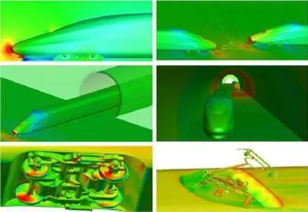
Fig.24 Computational results of train aerodynamics
4.1.4Reduced-scale test analysis
A 1:8 reduced-scale model is used for the wind tunnel test. The train model consists of three vehicles,a pantograph, wheel trucks,and windshields.The forces and pressures are measured in a regular wind tunnel,and aerodynamic noise sources and far-fiel aerodynamic noise are measured in a special low-noise wind tunnel.
Figure 26 shows the wind tunnel test models of different streamlined heads,and the scheme8○is CRH380A.Figure 27 shows a comparison of the pressure coefficien of the horizontalsectionforthenumericalsimulationandwindtunnel test.Figure 28 shows a comparison of the aerodynamic drag of different streamlined heads for the numerical simulation and wind tunnel test.Figure 29 shows a comparison of the lift force of the tail vehicle of different streamlined heads for the numerical simulation and wind tunnel test.
It can be seen from Figs.27,28,and 29 that the computationalresultsareveryclosetothewindtunneltestresults;the error of the aerodynamic drag is around 1%,and the error of theliftforceofthetailvehicleislessthan5%,whichcansatisfy the accuracy requirements of engineering computation. Thus,the numerical simulation is reliable.The wind tunnel test and the numerical simulation can be applied to the evaluation of the aerodynamic performance for each design scheme.

Fig.25 Aerodynamic optimization of streamlined head
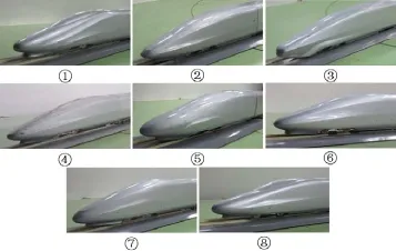
Fig.26 Wind tunnel test models of different streamlined heads
The 1:20 reduced-scale model is used for the moving model test.The train model also consists of three vehicles, a pantograph,wheel trucks,and windshields.The transient pressure fluctuatio on the train surface and the micropressurewaveatthetunnelexitcanbemeasured.Figure30shows acomparisonofthecompressionwaveoftrainspassingeach otherinatunnelforthenumericalsimulationandthemoving model test.
It can be seen from Fig.30 that the computational results are very close to the wind tunnel test results;the error of the compression wave is around 2%.Thus,the numerical simulation is reliable.The moving model test and the numerical simulation can be applied to the evaluation of the aerodynamic performance for each design scheme.
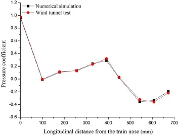
Fig.27 Comparison of pressure coefficien of horizontal section
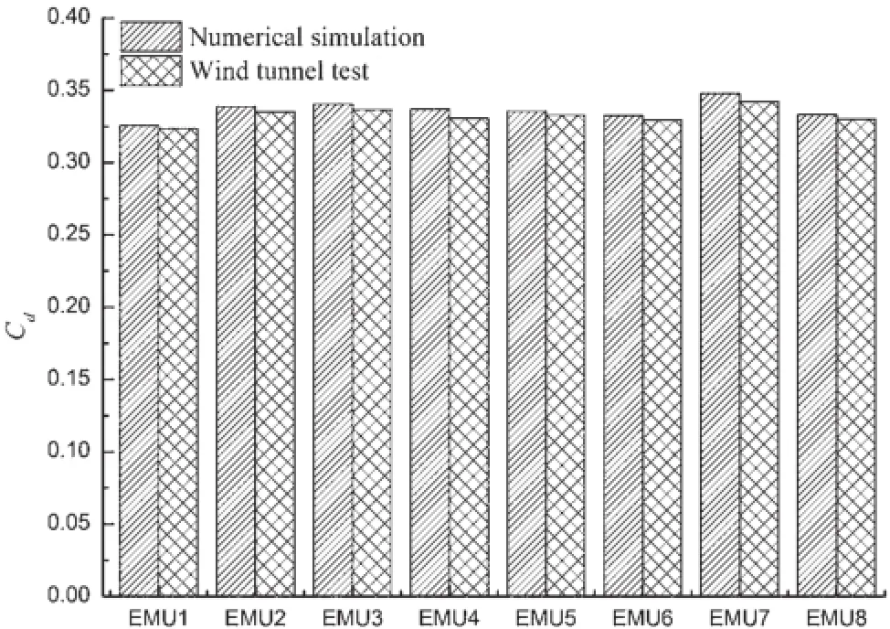
Fig.28 Comparison of aerodynamic drag of different streamlined heads
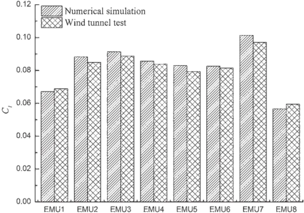
Fig.29 Comparisonofliftforceoftailvehicleofdifferentstreamlined heads
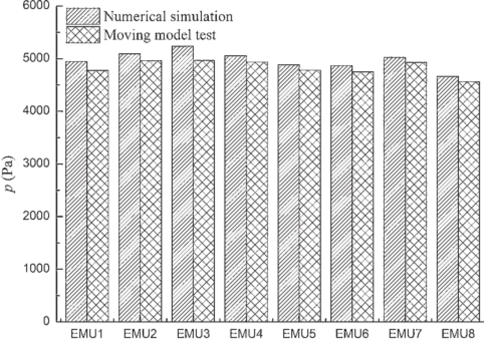
Fig.30 Comparison of compression waves of different streamlined heads
4.2Smooth design of body surface
4.2.1Electric-current collecting system
The electric-current collecting system has a complex geometry and intense turbulence flw,and the aerodynamic drag and aerodynamic noise are very obvious.Based on previous research,the flw fiel around the electric-current collecting system can be improved by proper diversion design,and the aerodynamic drag and aerodynamic noise can be reduced.In the present paper,various design schemes are used,and the numerical simulation and wind tunnel test are used to obtain the optimal design scheme.
Figure31showsthedesignschemesoftheelectric-current collecting system,including fi e various sinking platforms (ellipse,trapezium,rectangle,oval shaped,pentagon)of the pantograph,the sound-insulation wallboard around the pantograph,and the sound-insulation wallboard on both sides of the pantograph.The aerodynamic performance for each design scheme is studied by the numerical simulation and wind tunnel test,which is shown in Fig.32.Figure 33 shows a comparison of the aerodynamic drag of different design schemes for the electric-current collecting system.
The research results show that the computational values are close to the test values.By contrasting with the original scheme(having no sinking platform and sound-insulation wallboard),the aerodynamic drag for sinking platforms is reduced by 1%-4%.The sound-insulation wallboard can reduce the aerodynamic noise but may increase the aerodynamic drag.Through a comprehensive analysis, the pentagonal sinking platform is optimal.Compared with theoriginalscheme,theaerodynamicdragforthepentagonal sinking platform is reduced by 4.0%,and the aerodynamic noise for the pentagonal sinking platform is reduced by 1.0dB(A).
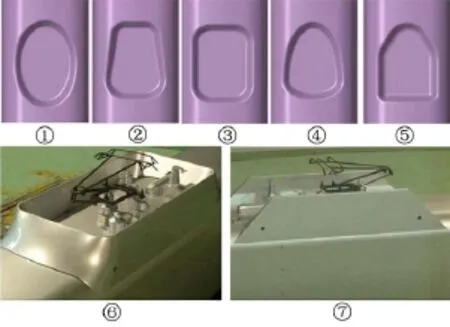
Fig.33 istribution along real Design schemes of electric-current collecting system
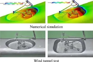
Fig.32 Research method for electric-current collecting system

Fig.33 Comparison of aerodynamic drag for electric-current collecting system
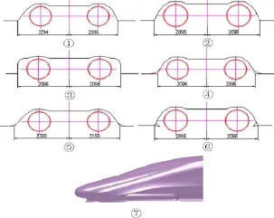
Fig.34 Design schemes of wheel truck compartment
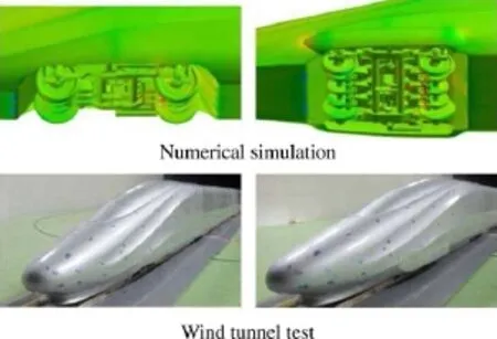
Fig.35 Method of researching wheel truck compartment
4.2.2Wheel truck compartment
The aerodynamic drag of the wheel truck compartment could account for 25%of the total aerodynamic drag.Based on previous research work and design experience,various design schemes considering the installation requirement of the wheel truck are used in the present paper,and the numericalsimulationandthewindtunneltestareusedtoobtainthe optimal design scheme.
Figure 34 shows the design schemes of the wheel truck compartment.Theaerodynamicperformanceforeachdesign scheme is studied by the numerical simulation and wind tunneltest,whichisshowninFig.35.Figure36showsacomparison of the aerodynamic drag of different design schemes for the wheel truck compartment.
The research results show that the smallwer the wheel truck compartment is,the smaller the aerodynamic drag.For the minimum size of the wheel truck compartment,the circular diversion scheme is optimal(scheme4○).The covered skirtplatecancontrolflwsintothewheeltruckcompartment and reduce the aerodynamic drag,especially under crosswinds.Bycontrastingwithscheme1○,theaerodynamicdrag for the covered skit scheme can be reduced by 6.1%undercrosswinds.The covered skirt plate can also reduce the aerodynamic noise,and the aerodynamic noise can be reduced by 1.3 dB(A)compared with scheme1○.
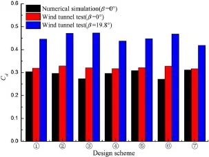
Fig.36 Comparison of aerodynamic drag for wheel truck compartment
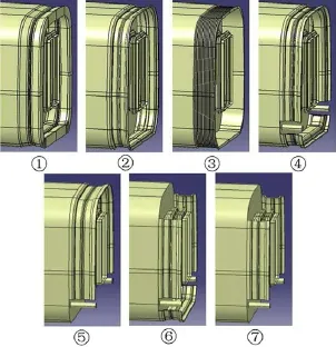
Fig.37 Windshield design schemes
4.2.3Windshield
The aerodynamic drag of the windshield could account for 5%of the total aerodynamic drag.Previous research shows that an enclosed windshield could effectively reduce aerodynamic drag and aerodynamic noise.Considering the installation and vehicle end equipment,seven different schemes are designed,and their aerodynamic performance are studied using a numerical simulation and a wind tunnel test.
Figure 37 shows windshield design schemes.The aerodynamic performance for each design scheme is studied using a numerical simulation and wind tunnel test,which is shown inFig.38.Figure39showsacomparisonoftheaerodynamic drag for different windshield design schemes.
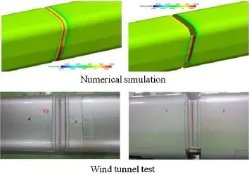
Fig.38 Method of researching windshields
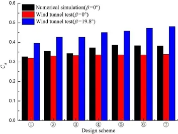
Fig.39 Comparison of aerodynamic drag for windshield
Theresearchresultsshowthatanenclosedwindshieldhas little influenc on the flw,and the flw has no separation.A semienclosed windshield singificantl influence flw,and the flw has separation.Scheme1○is the best and scheme 5○is the worst.Compared with sheme7○,the aerodynamic force of an enclosed windshield1○can be reduced by 5.7% with zero wind and 18%under crosswinds.
4.3Refinemen of numerical simulation
Asfortheoptimal streamlinedhead andthe smoothschemes of the body surface,a refinenumerical simulation of the full-scale real train with eight vehicles should be carried out, including a train running on open track,a train under strong crosswinds,trains passing each other on open track,a train passing through a tunnel,and trains passing each other in a tunnel,in order to verify the aerodynamic characteristics of the streamlined head and the smooth schemes of the body surface.The full-scale simulation results are similar to those of previous research.The preferred streamlined head and thesmooth schemes of the body surface have good aerodynamic performance,which can meet the design requirements.
5 Research results of train aerodynamics
Through the research on train aerodynamics,various design schemes with good aerodynamic performance have been obtained.The designed streamlined heads have a distinct appearance and a connotation of high culture,which can be used as an alternative scheme for the future design of streamlined heads.The aerodynamic design method of the high-speed train has been applied to various kinds of highspeed trains,which are as follows
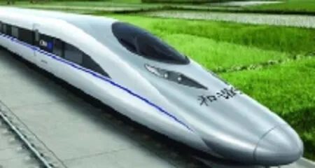
Fig.40 CRH380A
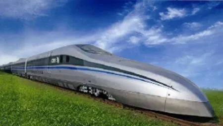
Fig.41 CRH380AM
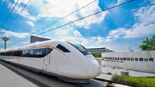
Fig.42 CRH6
(1)Aerodynamic design of CRH380A:the main objectives for the aerodynamic design of the CRH380A are to improvetheaerodynamicdrag,aerodynamicnoise,aerodynamic performance under crosswinds,and lift force of the end vehicle.The main technological schemes include optimization design of the streamlined head, semienclosed windshield,a sound-insulation wallboard on both sides of the pantograph,and sinking roofmountedantennas.Figure40showsthestreamlinedhead of the CRH380A.Compared with CRH2A,the aerodynamic drag of three vehicles is reduced by 17%,the lift force of the end vehicle is reduced by 51.7%,and the aerodynamic noise is reduced by 7%through the aerodynamic design.
(2)Aerodynamic design of CRH380AM:the main objectives for the aerodynamic design of the CRH380AM are to reduce the aerodynamic drag with small crosssectional area and large slenderness ratio,and improve the lift force of the end vehicle,the aerodynamic performance under crosswinds,and aerodynamic noise. The main technological schemes include optimization design of the streamlined head,enclosed windshield, lowdragandlownoisepantograph,andanair-resistance brake plate.Figure 41 shows the streamlined head of the CRH380AM.Compared with CRH380A,the aerodynamic drag of three vehicles is reduced by 9.1%,the lift force of the end vehicle is similar,the side force under crosswinds is similar and is reduced by 6.1%,and the aerodynamic noise is similar through the aerodynamic design.
(3)Aerodynamic design of CRH6:the main objectives for the aerodynamic design of the CRH6 are to reduce the aerodynamic drag with a large cross-sectional area and small slenderness ratio and improve the lift force of the end vehicle and aerodynamic noise.The main technological schemes include optimization design of the streamlinedhead,streamlineddesignofair-conditioning cover,smooth design of doors and windows,and a simplifie electric-current collecting system.Figure 42 showsthestreamlinedheadoftheCRH6.Comparedwith CRH2A,the aerodynamic drag of three vehicles is similar and the difference is less than 1.0%,the lift force of theendvehicle isreducedby40%,andtheaerodynamic noise is reduced by 0.5 dB(A)through the aerodynamic design.
(4)AerodynamicdesignofCRH2G:themainobjectivesfor the aerodynamic design of the CRH2G are to reduce the aerodynamic drag and aerodynamic noise with a large cross-sectional area and improve the aerodynamic performance under crosswinds.The main technological schemes include optimization design of the streamlined head,streamlined design of the air-conditioning cover, and a spoiler at the wheel truck compartment.Figure 43 shows the streamlined head of the CRH2G.Compared with CRH2A,the aerodynamic drag of three vehicles is reduced by 4.6%,the lift force of the end vehicle is reduced by 19%,the side force under crosswinds isreduced by 1.6%,and the aerodynamic noise is reduced by 1.0 dB(A)through the aerodynamic design.
(5)Aerodynamic design of standard EMU:the main objectivesfortheaerodynamicdesignofthestandardEMUare toimproveaerodynamicperformancewithalargecrosssectional area.The main technological schemes include optimization design of the streamlined head,enclosed windshield,and a smooth design of the electric-current collectingsystemandthewheeltruckcompartment.Figure44showsthestreamlinedheadofthestandardEMU. Compared with the CRH380A,the aerodynamic drag of eight vehicles is reduced by 15.7%,the lift force of the end vehicle is close to zero,the side force under crosswinds is reduced by 6.0%,and the aerodynamic noise is reduced by 1.0 dB(A)through the aerodynamic design (Fig.44).
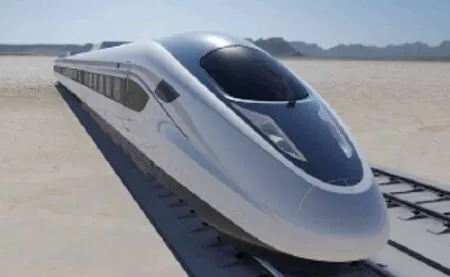
Fig.43 CRH2G
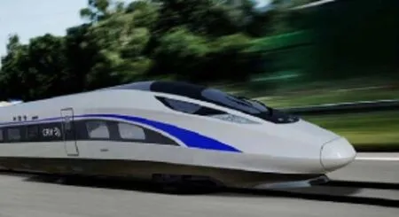
Fig.44 Standard EMU
Bycarryingoutaseriesofnumericalsimulations,reducedscale test,and full-scale test,the research results can contradicteachother.Onthisbasis,theproperboundaryconditions for the numerical simulation are determined.The numerical simulation is reliable,which can provide key technical support for the shape design of high-speed trains.
Through research on train aerodynamics,the overall idea, culture philosophy,and technical principle of the aerodynamic design on high-speed trains are established.A complete research process for the shape design of a highspeed train is established that can be applied to the design of streamlinedheadsofhigh-speedtrainsatspeedsof380km/h. Meanwhile,the perfect engineering manufacturing platform for the streamlined heads of high-speed trains is set up by system process innovation,which has quick manufacturing capabilities for new schemes and mass production capabilities for existing schemes.
6 Conclusions and future work
Research advances in the aerodynamic design of high-speed trains are presented in this paper,including research topics,research methods,technology schemes,and research results.Theaerodynamicdesignprinciple,aerodynamicperformance indexes,and design variables have very complex interrelationships.The aerodynamic design of high-speed trains is used to analyze the correlation between the aerodynamic performance indexes and design variables and carry out the optimization design of the train shape based on numerical simulations and reduced-scale testing.The aerodynamic design of the streamlined head of high-speed trains involves conception design,project design,numerical simulation,andreduced-scaletesting.Smoothdesignsareusedfor otherkeyparts,suchastheelectric-currentcollectingsystem, wheeltruckcompartment,andwindshield.Theaerodynamic design method established in the present paper has been successfully applied to various high-speed trains(CRH380A, CRH380AM,CRH6,CRH2G,and Standard EMU).However,theaerodynamicproblemsofhigh-speedtrainsarevery complex,and many problems should be researched in future work,including the following:
(1)Extensive research on boundary layer on train surface, revealing the flw mechanism and fluctuatio features.
(2)Extensiveresearchonsimilaritycriteriaofreduced-scale testing and improving the precision of the wind tunnel test and moving model test.
(3)Extensive research on engineering application of flw control technology and verificatio by full-scale testing.
(4)Extensive research on ground effects:the wind tunnel test cannot accurately simulate the relative motion between the train and the ground.As air moves along the test section,the boundary layer thickens,which may influenc test results.The ground effect of the wind tunnel test for high-speed trains should be studied in depth to formulate a more perfect theory and test method.
(5)Extensiveresearchonaerodynamicnoise:theseparation technology of aerodynamic noise and wheel/rail noise from the full-scale test results,the relationship between the wind tunnel test and the full-scale test,a comparison of the numerical simulation and wind tunnel test,and establishing an accurate numerical predictive model of the aerodynamic noise of high-speed trains.
(6)Extensive research on the limit value of pressure waves: pressure wave characteristics of trains for different streamlined heads,cross-sectional areas,train speeds, train lengths,and tunnels,for example;determining the allowable values for pressure waves based on a fatigue strength analysis of the train body.
(7)Establishing an aerodynamic design standard for highspeed trains,refininthe analysis platform for aerodynamic design on high-speed trains,and creating a database for aerodynamic design on high-speed trains.
AcknowledgmentsThis project was supported by the National Key Technology R&D Program of China(Grant 2013BAG22Q00)and the China Railway Science and Technology R&D Program(2015J009-D).
References
1.Schetz,J.A.:Aerodynamics of high-speed trains.Annual Review of Fluid Mechanics 33,371-414(2001)
2.Raghunathan,R.S.,Kim,H.D.,Setoguchi,T.:Aerodynamics of high-speed railway train.Progress in Aerospace Sciences 38,469-514(2002)
3.Baker,C.:The flw around high speed trains.Journal of Wind Engineering and Industrial Aerodynamics 98,277-298(2010)
4.Brockie,N.J.W.,Baker,C.J.:The aerodynamic drag of high speed train.Journal of Wind Engineering and Industrial Aerodynamics 34,2732290(1990)
5.Yu,M.G.,Zhang,J.Y.,Zhang,W.H.:Multi-objective optimization design method of the high-speed train head.Journal of Zhejiang University-Science A(Applied Physics&Engineering)14,631-641(2013)
6.Krajnovic,S.,Ringqvist,P.,Nakade,K.,et al.:Large eddy simulation of the flw around a simplifietrain moving through a crosswind flw.Journal of Wind Engineering and Industrial Aerodynamics 110,86-99(2012)
7.Cheli,F.,Ripamonti,F.,Rocchi,D.,etal.:Aerodynamicbehaviour investigation of the new EMUV250 train to cross wind.Journal of Wind Engineering and Industrial Aerodynamics 98,189-201 (2010)
8.Baker,C.J.:A framework for the consideration of the effects of crosswinds on trains.Journal of Wind Engineering and Industrial Aerodynamics 123,130-142(2013)
9.Yu,M.G.,Zhang,J.Y.,Zhang,K.Y.,et al.:Study on the operationalsafetyofhigh-speedtrainsexposedtostochasticwinds.Acta Mechanica Sinica 30,351-360(2014)
10.Howe,M.S.,Iida,M.,Maeda,T.,et al.:Rapid calculation of the compression wave generated by a train entering a tunnel with a vented hood.Journal of Sound and Vibration 297,267-292(2006)
11.Lee,J.,Kim,J.:Approximateoptimizationofhigh-speedtrainnose shape for reducing micropressure wave.Structural and Multidisciplinary Optimization 35,79-87(2008)
12.Tetsuya,D.,Takanobu,O.,Takanori,M.,et al.:Development of an experimental facility for measuring pressure waves.Journal of Wind Engineering and Industrial Aerodynamics 98,55-61(2010)
13.Talotte,C.:Aerodynamic noise:a critical survey.Journal of Sound and Vibration 231,549-562(2000)
14.Mellet,C.,Ltourneaux,F.,Poisson,F.,etal.:Highspeedtrainnoise emission:latestinvestigationoftheaerodynamic/rollingnoisecontribution.Journal of Sound and Vibration 293,535-546(2006)
15.Ikeda,M.,Suzuki,M.,Yoshida,K.:Study on optimization of panhead shape possessing low noise and stable aerodynamic characteristics.Quarterly Report of Railway Technical Research Institute 47,72-77(2006)
16.Yao,S.B.,Guo,D.L.,Sun,Z.X.,etal.:Multi-objectiveoptimization of the streamlined head of high-speed trains based on the Kriging model.Science China Technological Sciences 55,3495-3509 (2012)
17.BS EN 14067-2:Railway applications C Aerodynamics C Part 2: Aerodynamics on the open track.Brussels(2003)
18.Talotte,C.:Aerodynamic noise:a critical survey.Journal of Sound and Vibration 231,549-562(2000)
19.Noger,C.,Patrat,J.C.,Peube,J.,et al.:Aeroacoustical study of the TGV pantograph recess.Journal of Sound and Vibration 231, 563-575(2000)
20.Baron,A.,Molteni,P.,Vigevano,L.:High-speed trains:prediction of micro-pressure wave radiation from tunnel portals.Journal of Sound and Vibration 296,59-72(2006)
21.Li,T.,Zhang,J.Y.,Zhang,W.H.:A numerical approach to the interaction between airflw and a high-speed train subjected to crosswind.Journal of Zhejiang University-Science A(Applied Physics&Engineering)14,482-493(2013)
22.Krajnovic,S.,Ringqvist,P.,Nakade,K.,et al.:Large eddy simulation of the flw around a simplifietrain moving through a crosswind flw.Journal of Wind Engineering and Industrial Aerodynamics 110,86-99(2012)
23.Dorigatti,F.,Sterling,M.,Rocchi,D.,et al.:Wind tunnel measurements of crosswind loads on high sided vehicle over long span bridges.JournalofWindEngineeringandIndustrialAerodynamics 107–108,214-224(2012)
24.Schober,M.,Weise,M.,Orellano,A.,etal.:WindtunnelinvestigationofanICE3endcaronthreestandardgroundscenarios.Journal of Wind Engineering and Industrial Aerodynamics 98,345-352 (2010)
27 September 2015/Revised:9 October 2015/Accepted:21 October 2015/Published online:7 January 2016
✉San-San Ding
sf-dingsansan@cqsf.com
1School of Mechanical,Electronic and Control Engineering, Beijing Jiaotong University,Beijing 100044,China
2CSR Qingdao Sifang Locomotive&Rolling Stock Co.,Ltd., Qingdao 266111,China
杂志排行
Acta Mechanica Sinica的其它文章
- Correcting the initialization of models with fractional derivatives via history-dependent conditions
- Tomographic PIV investigation on coherent vortex structures over shark-skin-inspired drag-reducing riblets
- Analysis of the geometrical dependence of auxetic behavior in reentrant structures by finit elements
- The equilibrium stability for a smooth and discontinuous oscillator with dry friction
- Impact toughness of a gradient hardened layer of Cr5Mo1V steel treated by laser shock peening
- Why a mosquito leg possesses superior load-bearing capacity on water:Experimentals
