Augmented reality system to assist inexperienced pool players
2016-07-19SousaAlvesandRodriguescTheAuthor06ThisarticleispublishedwithopenaccessatSpringerlinkcom
L.Sousa(),R.Alves,and J.M.F.Rodrigues?cThe Author(s)06.This article is published with open access at Springerlink.com
Research Article
Augmented reality system to assist inexperienced pool players
L.Sousa1(),R.Alves1,and J.M.F.Rodrigues2
?cThe Author(s)2016.This article is published with open access at Springerlink.com
1LARSyS and Institute of Engineering,University of the Algarve,8005-139 Faro,Portugal.E-mail:L. Sousa,luiscarlosrsousa@outlook.com();R.Alves,ricardo_alvesr16@hotmail.com.
2LARSyS,CIAC and Institute of Engineering,University of the Algarve,8005-139 Faro,Portugal.E-mail: jrodrig@ualg.pt.
Manuscript received:2015-12-24;accepted:2016-02-25
AbstractPool and billiards are amongst a family of games played on a table with six pockets along the rails.This paper presents an augmented reality tool designed to assist unskilled or amateur players of such games.The system is based on a projector and a Kinect 2 sensor placed above the table,acquiring and processing the game on-the-fly.By using depth information and detecting the table’s rails(borders),the balls’positions,the cue direction,and the strike of the ball,computations predict the resulting balls’trajectories after the shot is played.These resultstrajectories,visual effects,and menus-are visually output by the projector,making them visible on the snooker table.The system achieves a shot prediction accuracy of 98%when no bouncing occurs.
Keywords computer vision;augmented reality(AR);Kinect;pool game
1 Introduction
The classical physics underpinning a game of pool can be hard to understand by a beginner or unskilled player,typically requiring many hours of practice to completely understand them.
In this paper,a visual application is introduced intended to help and assist amateur players by using the pool table as an interface,showing on-the-fly a prediction of what will happen when the player hits the white ball in its current position;menus or other visual effects can also be projected and accessed over the table or elsewhere.The system works for all varieties of tables and cues,regardless of their size,cloth or cue colour and material,or even the game type.It is based on a Kinect 2 sensor[1]and a projector placed above the table.The Kinect 2 sensor is responsible for capturing the game,which is then processed by a standard computer,enabling detection of game elements such as the table’s rails (borders),cue direction,and balls’positions,which are all used to predict a trajectory.The output result is then forwarded in real time to a projector,showing what might be the final result of that shot on the pool table.
Thecontributionsofthispaperarefirstly,introducing use of a depth sensor to augmented reality(AR)for a pool or billiards game system,and making the detection functions of the system more reliable:novel methods are proposed to detect the motion,the pool balls’centres(even when several balls are in contact),the cue position and direction,and the strike of the ball.This basic information is used to simulate the basic physics of the game based on depth information.Secondly,the system itself is an augmented reality pool application that works in real clubs,pubs,or exhibition environments,without the need for any changes to equipment including balls,cues,table,lighting,etc.
Section2presentsthestateoftheart,while Section 3 explains in detail the system’s implementation:detection of the table borders,balls,cue and strike,the physics computation,andhowoutputismappedtotheprojector. Section 4 presents tests and results in an exhibition environment.The final section presents a discussion,conclusions,and future work.
2 State of the art
Many examples of tools exist for the games of pool,snooker,and billiards.Many of them are focusedon analysing video footage mostly to give a 3D representation of the game[2-4].Unlike those systems,e.g.,Ref.[2],the application proposed in this paper is an AR tool that enhances on-the-fly the perception of what the player is currently doing by projecting a calculated trajectory onto the table. Other research uses a robot capable of choosing and executing shots on a real table,although these robotic systems have been tested under laboratory conditions[5-7].
Leckie and Greenspan[8]presented a paper about the physics in a game of pool;also see Refs.[9,10]. One of these authors also presented a tool similar to the one proposed in this paper:ARPool is a projector-camera system that provides the player real time feedback on the surface of the table[11]. However,no publications appear to be available regarding this tool(only a web page).The present authors introduced in Ref.[12]an initial version of the system(PoolLiveAid),very similar to Refs.[11,13],using a single Full HD webcam as a sensor to acquire what is occurring on the table.Despite the good results provided by the system,some limitations exist,e.g.,it is very difficult to detect and individually distinguish each ball when two or more balls are in contact.Also when using the system in real pool clubs,some shortcomings were observed in ball detection due to the imposed lighting.
Other systems exist:Shih et al.[10]presented a system to compute the best sequence of shots given a starting cue ball position.Later,Shih[9]presented three novel game strategies to investigate the effect of cue shot planning on game performance.The above installations almost all use RGB cameras,but other sensors can be used.For instance,3D sensors are gaining more attention currently,due to their greater functionality.
The Microsoft Kinect[1]is one of the best known and was popularized by the video gaming industry,but now many applications can be found using it;see,e.g.,Refs.[14-16].By using the above mentioned 3D sensor and the depth information it provides,in comparison to Refs.[11,12],the tool proposed in this paper increases the robustness of the application with respect to suboptimal lighting conditions,relative to our previous tool[12].
Theuseof3Dsensors,insteadofRGB cameras,doubtless provides benefits in this type of application,such as the aforementioned immunity to changes in lighting conditions,making cue and ball segmentation more robust than if done purely using colour,especially for separating balls that are in contact.By using depth information,as it will be shown,the segmentation of the cue and balls can be very precise.There are no main disadvantages in the use of the Kinect in this particular application,except if an infra-red source causes interference in the field of view of the sensor,stopping it working properly.
The most similar tool to the one presented in this paper is OpenPool[17],an open source system that uses a 3D depth sensor to detect balls’positions,and uses Unity software to compute animations that are mapped onto the table using a projector.This tool can also detect when a ball is successfully potted using auxiliary hardware installed in the table’s pockets.For ball detection,it uses the same sensor technology as this paper(a Kinect 2),but the similarity stops there.In our system,the cue is also detected and the basic physics of the strike of the ball are computed.The goal of OpenPool seems(at least for now)to be an animated pool table,using the elements(the balls)that are on the table. Our system also allows animations,but the main difference is in purpose,allowing the inexperienced player to comprehend the basic physics of the game. By moving the cue near the ball,it is possible to see on-the-fly a projection of its expected trajectory.
3 System implementation
As already mentioned in the introduction,the system consists of(a)a pool table,of any size,with the usual balls and cue,(b)a Microsoft Kinect 2[1],(c)any ordinary laptop or desktop computer capable of analysing inputs from the Kinect,and(d)a projector to project the computed trajectories and balls’locations.
In terms of setup,the projector can be placed above the table(Fig.1 left,fixed in the celling)or on a side wall,as long as it can project onto the whole table.A single Kinect 2(Fig.1 left,the black sensor on the white support)can cope with tables of size up to 2.5m×1.4m at a height of up to 1.75m;the dimension used for the experimental setup presented in this paper is 2.2m×1.1m,with the Kinect placedat a height of about 1.6 m.For larger tables,two or more Kinect sensors could be used to acquire the entire game field,requiring an additional(trivial)algorithm to merge the acquired frames.All the algorithms presented in this paper could be used with more than one Kinect sensor(in Fig.1 left,the ends of the support were used to test with two Kinect 1 sensors).Finally,the Kinect should be placed more or less above the centre of the table:while other positions could be used,if the Kinect were placed for instance on a side wall,this would severely impair the Kinect’s depth resolution,hampering detection of game elements,as would the occlusion of some elements.
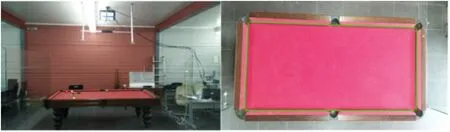
Fig.1 Left:prototype.Right:a region of the colour frame acquired by the Kinect,with the 4 corners(and rails)marked.
The system is divided into 5 main modules(Fig.2). System setup computes the table boundaries and all transformation matrices.Motion detection and categorization detects motion on the table.If motion and thus game play has stopped(no motion was detected in the current frame at time t,but motion was detected at time t-1),then it executes the ball detection and classification module.However,if motion was detected in the current and previous frames,then two situations can exist:the balls are in movement on the table,or a sudden movement was detected,assuming that a player is approaching to play.In this case,using the balls already detected in a previous iteration,shot prediction and strike detection starts to execute.Again two situations can occur:cue detection is needed,and physics simulated,or after the cue ball has been struck,balls are still moving and need to be detected once they stop.Finally,the visualization module ensures all outputs,strike prediction,visual effects involving the balls,and menus,are projected onto the table.
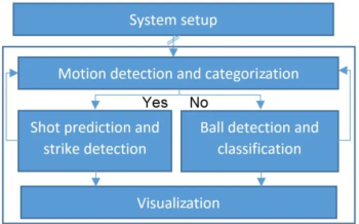
Fig.2 Block diagram of the system.
3.1System setup
As mentioned,neither the Kinect nor the projector needs to be placed in the centre of the table,so two important preprocessing steps must compute: (i)the perspective transform of frames acquired by the sensor,and(ii)the perspective transformation of images that will be displayed by the projector.Plus,(iii)a reference depth frame(R)is determined.This information is saved to file,and loaded every time the system initializes;it only needs to be computed again if the table,the Kinect sensor,or the projector changes position.
The Kinect sensor provides at each time step an RGB frame,I(x,y),and a depth frame,D(x,y);in the latter each pixel(x,y)represents the distance of sensed objects to the sensor.Smaller pixel values correspond to points closer to the sensor.The Kinect depth frame has 16 bit resolution,so pixel values range from 0 to ND=65535.
For step(i)perspective transformation,the borders of the table’s playing area are needed.These are computed using the RGB image I;a Canny edge detector[18],then a Hough transformation[18]are applied.As several lines are detected,only (almost)horizontal and vertical lines are selected,and their intersection points are shown to the user (see implementation details in Ref.[12]).The user is asked to validate these corners,adjusting them if necessary,as small errors in corner positions lead to larger trajectory errors.
Let Ct{1,...,4}(x,y)be the positions of the corners of the playing area from top-left in clockwise order (see Fig.1 right).Given the four points determined above and the four reference points of the mapping,i.e.,(0,0),(M,0),(M,N)and(0,N),with M= 2×N and N=[dist(Ct2,Ct3)+dist(Ct1,Ct4)+ (dist(Ct1,Ct2)+dist(Ct4,Ct3))/2]/4,where dist means Euclidean distance,then a transformation matrix[18]MPtKcan be computed.Thus,the initial depth frame D can now be transformed to a depth frame containing only the playing area,D0=MPtKD.We set M=2×N as a professional pool table has a length twice its width.
Computing(ii)the perspective transformation of the images,is necessary only for projectors that do not have a built-in function that lets the user choose the four corners of the projection.In such cases,a similar computation to(i)is necessary. The visualization component P,can be transformed toP,where MPtPis the perspective transformation for the projector.
Also,during setup we compute(iii)the table reference depth frame,R.Depth frames acquired by the Kinect present small inconsistencies and noise,which need to be removed in order to improve detection and reliability.As during setup time,and while no motion is occuring on the table,a small delay of say 1s in the computation is not important,and an average of the most recent frames is computed to remove noise.The filter used for time t,Dat,averages the previous Npdepth frames:Dat(x,y)=The result of this process is illustrated in Fig.3,the 1st row,right(with Np=25),the middle showing an example of an original depth frame D,extracted from the empty table on the left.Choosing a higher Npimproves reliability but increases the delay.The reference depth average frame is the initial Da(empty table)found at setup,after applying the transformation Ra0=MPtKDa(see Fig.3,the 2nd row,left).
In the remaining text,the notationsandrepresent frames to which the transformations MPtKand MPtPhave been applied,repsectively.For visualization purposes,all pixels from the figures representing the depth frames were divided by 16,clamping any values higher than 255,then they were brightened by 10%and their contrast was increased by 90%.This causes the images in Fig.3 to show some banding,representing very small changes in depth that have been amplified for visualization purposes.This banding would be concentric with the sensor if it were centred and parallel to the table.In this case,it had a slight pan and tilt,but this does not affect any of our algorithms.
3.2Motion detection and categorization The motion detection and categorization module determines the phase of the game and what step of the algorithm should be exectuted next(see Fig.2).To detect motion the depth frame D is used.For frames that are expected to have motion,or with motion,the noise removal is applied in real time using a Gaussian filter,G[18],with σ=2,Dgt(x,y)=G(Dt(x,y)).
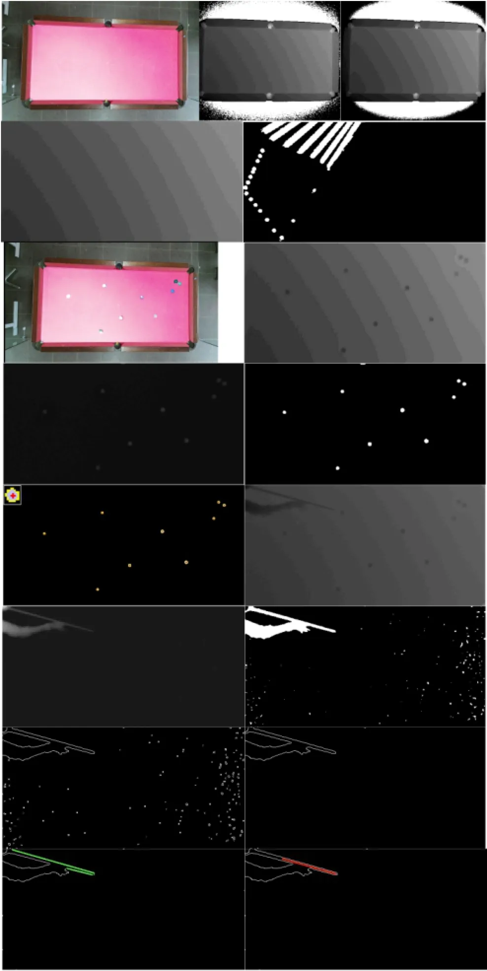
Fig.3 Top row:left:empty table,middle:depth frame D,right: after noise removal Da.The 2nd row:left:reference frame Ra0,right:example of Mb frame.The 3rd row:left:table with balls,right:Da0t.The 4th row:left:Btwith blobs where possible balls might be,right:binary image Bbt.The 5th row:left:Bctimage with contours marked in yellow and the balls’centres in red,right: example of a current frame containing the player’s hand and the cue Da0t.The 6th row:Ctand Cbt.The 7th row:left:Cet,right:a frame with blobs due to noise removed.Bottom row:left:result showing multiple lines found on the cue,right:a single line(in red)resulting from cue detection.
3.2.1Motion detection
Motion detection can be implemented using thedifference between two depth framesbut using this approach,small differences between two consecutive frames are almost undetectable and can be confused with noise.Thus,a comparison between the current frame and multiple other frames is used:Mt(x,y)where Mtis the motion detection frame at time t,which compares the current frame Dg0tand the previous Np=40 frames(around 1.5s).A binary image is computed indicating where motion exists:Mbt(x,y)=1,if Mt(x,y)>Tm,otherwise Mbt(x,y)=0,with Tm=0.05%ND.Figure 3,the 2nd row,right,shows an example including a cue and a ball being struck.
3.2.2Motion categorization
The system uses a binary variable ω to indicate the motion status of the system,1 meaning motion and 0 meaning no motion.The system starts by default with ω=1.The number of white pixels detected in Mbtgives us information about whether motion is occurring in the current frame:Cmt=A counter,Kt,manages false movements detected by the procedure above:
(i)If the current value of the system state is no motion,then it is necessary to detect when motion starts,and for this the counter Ktis incremented if Cmtis higher than K1=0.05%M,otherwise decremented(values lower than 0 are clamped to 0).If the counter Ktreaches K2=25(around 1 s;25 frames),then it is considered that motion has started,changing the state to motion and we set Kt=0.
(ii)On the other hand,if the system state is motion then the counter is incremented if Cmtis lower than K1,otherwise decremented(again,values lower than 0 are clamped to 0).If the counter Ktreaches K2,then it is considered that motion has stopped,changing the state to no motion and we set Kt=0.Using Kt,motion can be characterized as follows:
(ii.1)Stopped:If motion was not detected in the current frame,but was detected in the previous frame,ωt-1=1∧Kt=K2,then ωt=0∧Kt=0.
(ii.2)Started:If motion was detected in the current frame,but was not detected in the previous frame,ωt-1=0∧Kt=K2,then ωt=1∧Kt=0.
(ii.3)Non-existent(no motion):If motion was neither detected in the current or previous frames, ωt-1=0∧Kt<K2,then ωt=0.
(ii.4)In motion:If motion was detected in either the current or previous frame,ωt-1=1∧Kt<K2,then ωt=1.
Having characterized the motion,it is now possible to project different visual outputs concerning the motion event taking place,and to detect the balls’positions and the remaining elements of the game. 3.3Ball detection and classification
Ball detection and classification is triggered after motion has stopped,and uses the reference depth average frame Ra0determined in the setup step(see Fig.3,the 2nd row,left).
3.3.1Ball detection To detect the balls’positions on the table we compute,where Bt is the frame containing blobs where balls might be (see Fig.3,the 4th row,left).A binary threshold is applied to obtain a binary frame containing the balls (see Fig.3,the 4th row,right),where Bbt(x,y)=1 if Bt(x,y)>Tb,and 0 otherwise;Tb=13/16Bw,where Bwis the ball height determined during system setup from depth information.It is important to stress that the threshold must be between T1= 7/8Bwand T2=3/4Bw(see Fig.4),so that Tb>T2,otherwise balls that are in contact with each other will forming a single blob,and thus be recognised as just one ball.
Thenextstepconsistsofapplyingthe morphological erosion operator E,with the goal of removing any remaining noise(small blobs)that still persist:Bet=E(Bbt).Finally,we compute the ball centre and radius(r).A ball has a peak in the depth frame at its centre,giving the exact position(x,y)of the ball on the table.To find these peaks,allowing for noise in the Kinect depth frames,a contour finder C[19]is applied,Bct=C(Bet).
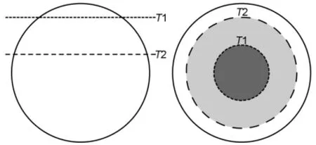
Fig.4 Side and top view of a ball,with T1 and T2 reference depths.
For each contour a local maximum is computed in Bt,corresponding to the coordinates of the ball’s centre.Figure 3,the 5th row,left,shows in yellow the contour of each ball,and in red its peak(at the top left of the image,for clarity,a zoomed view of one of the blobs/balls is shown).
3.3.2White ball classification
Having detected all balls,the white ball has to be classified,as it is the only ball the cue may hit. The I0colour frame from the Kinect is converted to HSV colour space,,and the pixels’V component values inside each ξicontour in Bctare summed.The contour with the biggest sum is classified as the white ball,with centre(xbc,ybc),with respective contour index i,where W(x,y,i)=and Nbis the number of ball contours in Bct.
A similar process could be used to classify other balls.
3.4Shot prediction and strike detection
With all balls detected and the white ball found,cue detection is the next step,followed by shot prediction and strike detection.
3.4.1Cue detection
Cue detection is based on 5 steps:(i)waiting for all balls to stop moving,(ii)defining the depth reference frame of the table,(iii)computing the difference between the depth reference frame and the current depth frame,(iv)finding the largest blob,if any exists(removing all smaller ones),and(v)detecting the centre line for the largest blob from a starting point near the white ball.
In more detail,when motion stops and triggers ball detection,a reference frame Qa0is captured(see Fig.3,the 3rd row,right).Since the reference frame contains the balls at the instance motion stopped,the difference between it and any current frame(see Fig.3,the 5th row,right)can only be a player,a cue,or both.Thus,cue detection can be achievedFig.3,the 6th row,left),then creating a binary frame,removing small inconsistencies due to noise: Cbt(x,y)=1,if Ct(x,y)>Tc;0,otherwise,where Tc=0.05%ND(see Fig.3,the 6th row,right).
Using a contour finder[19]on Cbt,the contours of all blobs are found(γi),one being the cue(usually with the hand and arm attached),and all others being noise.If the cue exists in Cbt,then it has a larger area than the other blobs found(see Fig.3,the 7th row,left).To avoid false cue positives,first we find the blob with the largest area,Al=max(Ai),where Aiis the area of each blob γiin frame Cbt. We then compute the average area of the remaining blobswhere Ncis the total number of blobs.The next step consists of removing from Cbtall blobs Aiwhose area is less than 100×At this point,if a blob still exists in frame Cct(x,y)it could be a hand,a cue,or more probably a cue with a hand(see Fig.3,the 7th row,right).
To detect the cue,and later its direction,a Hough line transform[20]is computed for Cct(x,y).Now,it is necessary to select only lines that belong to the cue.All lines that both start and end more than 5 times the ball diameter from the cue ball are discarded,thus removing possible lines detected due to the user’s arm.All remaining lines having the same angle,±5◦(see Fig.3,bottom row,left,in green),are then used to determine an average line (see Fig.3,bottom row,right,red line),defined by (xc,yc),a point on the line,and(cx,cy),the direction vector of the line.
3.4.2Shot prediction
With the white ball located and the cue detected,it is possible to predict the trajectory of the cue ball after it has been struck.To check if the cue is being aimed at the white ball(see Fig.5),(i)the equation of the cue line,v(x,y)=(xc,yc)+kc(cx,cy)is computed(see Section 3.4.1),as well as(ii)the equation of the ball,r2=(x-xbc)2+(y-ybc)2(see Section 3.3.2),and(iii)we check if they intersect,(xc-k×cx-xbc)2+(yc+k×cy-ybc)2=r2.
If kcis a real number,then the cue is aimed at the white ball,and the physics can now be simulated. Knowing the vector representing the direction of the cue(v),it is necessary to compute vectors at each table boundary in order to calculate the respective reflected trajectory(see Fig.5).Taking into consideration that the centre of the ball,due to the ball’s finite radius,does not reach the table boundary,the table boundary vectors are computed as follows,clockwise around the table:bi(x,y)=directions are respectively,=(M,0) and
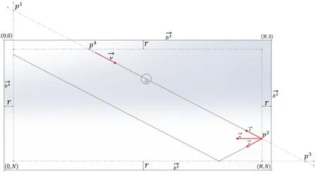
Fig.5 Shot preview,trajectory computation.
Finding if an intersection exists,and getting the contact point,for every boundary i,is then determined usingbiycy).An intersection between the boundary and the cue trajectory only occurs when
If an intersection occurs,the possible contact points p1to p4(with(pix,piy)the coordinates of contact with the table boundary)with the table boundary are calculated using(pix,piy)=(xib,yib)+ kib(yib-yc);see Fig.5.
Since the line of the cue can intersect more than one boundary,the true physical intersection needs to be found.Out of all boundary intersection points,the nearest point of contact to the ball that also has the same direction as the vector(cx,cy)is found. The point where the contact occurs,(xf,yf),is the one satisfying(xf,yf)=min|(pix-xbc,piy-ybc)|∧((cx×bix)>0)∧((cy×biy)>0).
The reflection between the boundary and the current direction also needs to be calculated,for prediction of the trajectory afterwards.Using the boundary f selected by the process above,a normal vector to that boundary is calculated,n(x,y)= v(-bfy,bfx)as well as the vector with the opposite direction to the current trajectory(v),l= (xcxbc,yc-ybc).The reflection trajectory is then calculated to be o=2n(l·n)-l.
This process can be repeated any number of times and should be repeated just enough times as the number of boundaries the ball would hit in its trajectory.Figure 6 shows examples of 2 boundary collisions in the 1st row and 3 collisions in the bottom row,left.
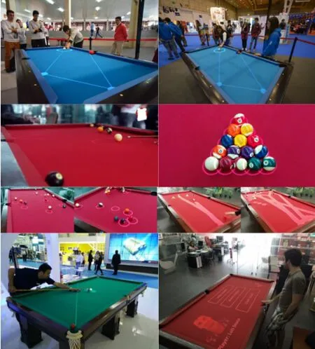
Fig.6 Examples of the application working at different exhibitions and sites.Bottom right:menu example.
3.4.3Strike detection
Withapredictedtrajectorycomputed,strike detection is necessary to detect when the white ball starts moving,in order to stop calculating(and projecting onto the table)trajectories.The detection of this movement uses the reference image Qa0(see Section 3.4.1),extracting a region of interest(RoI)τ,centred at the current position of the white ball,with size d×d,where d=2r.
3.5Visualization
Having found all game elements and categorised the motion(see Section 3.2.2),it is now possible to project visual information onto the table.An image P is dynamically created with several options depending on the game stage(see Fig.6):(i)circles centred on the balls,(ii)predicted trajectories,(iii)animations,and(iv)menus.If necessary(see Section 3.1),the projector transformation is applied to P,returning the projected table image P00.Details of the menus and effects,and the corresponding interface are outside the scope of this paper.
4 Tests and results
Figure 6 shows some examples of the system working in real crowded environments,at 3 different exhibitions,each lasting 1 week.All tests were performed and statistics gathered during these weeks with real users,all of whom were first-time application users and unknown to the development team.Two hours(evenly distributed between the exhibitions)of recordings were made,in random 10 minute slots at various time of day,on 4 different days,for a total of 163 shots.In each case,the ground truth was manually created.Table 1 summarises the results.Video extracts from the exhibitions can be seen on Ref.[21](2014 onwards postings).
The tests were divided into 8 categories.For table boundary detection,two different tables were used,both different from the one used during development(a red one),also having different lighting conditions.Table boundaries were always automatically detected(100%)with less than 3-pixel errors.It is important to stress that more tests were conducted during development,the final ones always result in 100%success rate with less than 3-pixel errors.The algorithm was tested 3 times,once at each exhibition.
Motiondetection:inthe163shotsmade,motiondetectionworked100%ofthetime,correctly triggering the ball detection algorithm.The maximumdelayobtainedbetweenthemotion actually stopping and the ball detection was around 2-3 s,for Np=40(most users did not notice this delay).A further set of tests with Np=25 was also made(with 1 s delay),but in this case the motion detection success rate dropped to 90%.
For ball detection,in the 163 shots made,there were a total of 605 balls to be detected(not all balls were placed on the table in every shot).All balls were successfully detected but there were 17 false positives,due to failure to filter noise correctly. The white ball was successfully detected 91%of the time.19 times of failure were due to a striped ball occuring with its white part facing upwards in an area with higher luminosity,while the others(16 times)were due to the white ball being potted.Balls were detected with a maximum of 10 mm error of their true positions,due to noise in the depth frames and distortion of the projector,with the error increasing for balls further from the centre of the table.
Cue detection always worked in the above 163 shots,and so did stroke detection.Nevertheless,some errors were noticed in the cue detection outside these tests,when a player did not behave in accordance with pool rules or other expectations,e.g.,putting two cues in the pool table area or there several people were present with their hands moving near the table border.During stroke detection,a small delay of around 1s could sometimes be noticed,mostly due to the cue occupying the position the white ball previously occupied.
Finally,shot prediction was the most difficult test to quantify.Since the goal of the application is to assist inexperienced players,and since they may not know how to hold the cue and take a shot,hittingthe white ball on the side and giving it spin was not counted in these statistics.Ball motions that did not bounce were successfully predicted in 98%of cases,while balls that bounced once were successfully predicted 80%of the time and balls that bounced twice were successfully predicted 53%of the time. More bounces were not included in this test,due to their poor results(a bounce being each contact the white ball makes with a table boundary).
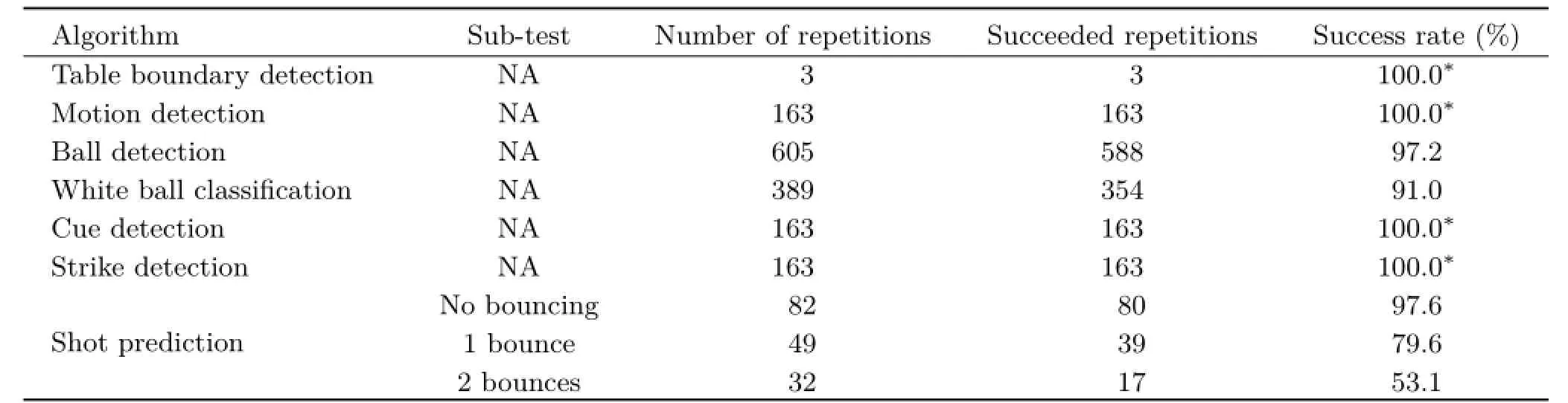
Table 1 Test results
5 Conclusions
We have presented an application that aids a beginner to play pool,based on a Microsoft Kinect 2 sensor,allowing the detection of table boundaries,the balls,and the cue with high accuracy.All the algorithms have been demonstrated to be very robust against changes in lighting conditions and noise.A projector,placed above the table,shows in real time the computed trajectory in order to give a player a perception of what will happen on that particular turn.
The system works in real time,and all testing was done in real environments,showing very good results.A comparison with previous systems is difficult,as to the best of our knowledge there is no suitable test data or ranking method.However,our system works in real time and in real conditions,whereas systems like Refs.[2,4,22]work with video(or video streams)taken from pool or snooker championships,with very stable and controlled conditions(lighting,player positions,etc.),or expect a controlled environment because of the use of robots[5-7].
The most similar works are Refs.[9-13].There is no technical publication available to make any type of comparison to Ref.[11].In comparison to Ref.[12](our previous work),the system has improved in terms of reliability by about 10%-20%,depending on the test considered,while improving reliability by 1%-5%over using two Kinect 1 sensors(in unpublished work).Considering Ref.[12]in more depth,in terms of lighting,the Kinect enables precise detection of game elements even when lighting conditions change drastically,which was detrimental to the results when using a webcam.Secondly,since the colour segmentation used in Ref.[12]is now replaced by balls and cue detection,balls or cues that have very similar colour to the cloth on the table are now more easily detected,leading to a 30% improvement.Finally,Shih et al.[9,10]presented very interesting work in terms of physics of the game(better simulation than that presented here),but they used a very small table under controlled conditions.They used an RGB camera to extract the balls and cue,which when applied in real situations,e.g.,under different lighting in pubs and exhibitions,with different table cloths,etc.,is unlikely to be as reliable as our present approach(see our previous work[12],and the discussion above).In terms of augmented reality,they only showed their output on a computer screen.
In summary,the most important contribution of our paper is the complete system,that by using the Kinect sensor,has turned out to be very reliable and can work in any environment using any table cloth,balls,or cues.In the near future,work will focus on increasing the number of menu options,improving the augmented reality menu,and implementing an automatic scoring system allowing us to collect more statistics.An important focus will be the prediction of the movement of the coloured balls after theyare hit by the white ball.Also,the physics can be improved if the stroke force is estimated,as well as determining the exact position at which the cue hits the white ball.This last point will be for sure a very challenging goal.
Finally, afterthis, testswithestablished professional players should be performed in order to validate the implemented physics,by tracking the struck ball and comparing with the previous system prediction.Improving the physics and validating it with the aid of professional players will enable us to implement a set of tests to show whether the application can also teach beginners how to play or improve their skills.
Acknowledgements
This work was partly supported by the Portuguese Foundation for Science and Technology(FCT),project LARSyS UID/EEA/50009/2013,and the INALUX company(http://www.inalux.com/).We also thank the anonymous reviewers for their very significant and useful contributions to the paper.
References
[1]Kinect2.Kinect for Windows.2015.Available at http://www.microsoft.com/en-us/kinectforwindows/.
[2]H¨oferlin,M.;Grundy,E.;Borgo,R.;Weiskopf,D.;Chen,M.;Griffiths,I.W.;Griffiths,W.Video visualization for snooker skill training.Computer Graphics Forum Vol.29,No.3,1053-1062,2010.
[3]Jiang,R.;Parry,M.L.;Legg,P.A.;Chung,D. H.S.;Griffiths,I.W.Automated 3-D animation fromsnookervideoswithinformation-theoretical optimization.IEEE Transactions on Computational Intelligence and AI in Games Vol.5,No.4,337-345,2013.
[4]Ling,Y.;Li,S.;Xu,P.;Zhou,B.The detection of multi-objective billiards in snooker game video.In: Proceedings of the 3rd International Conference on Intelligent Control and Information Processing,594-596,2012.
[5]Archibald,C.;Altman,A.;Greenspan,M.;Shoham,Y.Computational pool:A new challenge for game theory pragmatics.AI Magazine Vol.31,No.4,33-41,2010.
[6]Landry,J.-F.;Dussault,J.-P.;Mahey,P.Billiards: An optimization challenge.In:Proceedings of the 4th International C*Conference on Computer Science and Software Engineering,129-132,2011.
[7]Nierhoff,T.;Kourakos,O.;Hirche,S.Playing pool with a dual-armed robot.In:Proceedings of IEEE International Conference on Robotics and Automation,3445-3446,2011.
[8]Leckie,W.;Greenspan,M.An event-based pool physics simulator.In:Lecture Notes in Computer Science,Vol.4250.Van den Herik,H.J.;Hsu,S.-C.;Hsu,T.-S.;Donkers,H.H.L.M.Eds.Springer Berlin Heidelberg,247-262,2006.
[9]Shih,C.Analyzing and comparing shot planning strategies and their effects on the performance of an augment reality based billiard training system. International Journal of Information Technology& Decision Making Vol.13,No.3,521-565,2014.
[10]Shih,C.;Koong,C.-S.;Hsiung,P.-A.Billiard combat modeling and simulation based on optimal cue placement control and strategic planning.Journal of Intelligent&Robotic Systems Vol.67,No.1,25-41,2012.
[11]ARPool.Augmented reality:Pool.2015.Available at http://rcvlab.ece.queensu.ca/qridb/ARPOOL.html.
[12]Alves,R.;Sousa,L.;Rodrigues,J.M.F.PoolLiveAid: Augmented reality pool table to assist inexperienced players.In:Proceedings of the 21st International Conference on Computer Graphics,Visualization and Computer Vision,184-193,2013.
[13]Larsen,L.B.;Jensen,R.B.;Jensen,K.L.;Larsen,S.Development of an automatic pool trainer.In: Proceedings of the 2005 ACM SIGCHI International Conference on Advances in Computer Entertainment Technology,83-87,2005.
[14]Ahmed,F.;Paul,P.P.;Gavrilova,M.L.DTW-based kernel and rank-level fusion for 3D gait recognition using Kinect.The Visual Computer Vol.31,No.6,915-924,2015.
[15]Song,X.;Zhong,F.;Wang,Y.;Qin,X.Estimation of Kinect depth confidence through self-training.The Visual Computer Vol.30,No.6,855-865,2014.
[16]Abedan Kondori,F.;Yousefi,S.;Liu,L.;Li,H. Head operated electric wheelchair.In:Proceedings of IEEE Southwest Symposium on Image Analysis and Interpretation,53-56,2014.
[17]OpenPool.OpenPool.2015.Availableathttp:// www.openpool.cc/.
[18]Russ,J.C.The Image Processing Handbook,6th edn. CRC press,2011.
[19]Suzuki,S.;KeiichiA be.Topological structural analysis ofdigitizedbinaryimagesbyborderfollowing. Computer Vision,Graphics,and Image Processing Vol.30,No.1,32-46,1985.
[20]Duda,R.O.;Hart,P.E.UseoftheHough transformation to detect lines and curves in pictures. Communications of the ACM Vol.15,No.1,11-15,1972.
[21]PoolLiveAid.PoolLiveAid Facebook.2015.Available at https://www.facebook.com/Poolliveaid.

[22]Legg,P.A.;Parry,M.L.;Chung,D.H.S.;Jiang,R.M.;Morris,A.;Griffiths,I.W.;Marshall,D.;Chen,M.Intelligent filtering by semantic importance for single-view 3D reconstruction from Snooker video. In:Proceedings of the 18th IEEE International Conference on Image Processing,2385-2388,2011. L.Sousaisaresearcheratthe UniversityoftheAlgarvewitha master degree in electrical and electronic engineering.He is a member of the LARSyS(ISR-Lisbon)laboratory and he is the co-author of 14 scientific publications.His major interests lie in electronic systems,embedded systems,and computer vision.

R.Alveshasamasterdegreein electric and electronic engineering.He is a researcher at the University of the Algarve working with depth sensors. He is a member of the LARSyS(ISRLisbon)laboratory and he is the coauthor of 9 scientific publications.He also spends some of his time developing other electronics and programming projects.

J.M.F.Rodrigues graduated in electrical engineering in 1993,got his M.Sc.degreeincomputersystems engineeringin1998, andachieved aPh.D.degreeinelectronicsand computer engineering in 2008 from the University of the Algarve,Portugal. He is an adjunct professor at Instituto Superior de Engenharia,also in the University of the Algarve,where he has lectured computer science and computer vision since 1994.He is a member of the LARSyS (ISR-Lisbon)laboratory,CIAC and the associations APRP,IAPR and ARTECH.He has participated in 14 financed scientific projects,and he is the co-author of more than 120 scientific publications.His major research interests lie in computer and human vision,assistive technologies,and human-computer interaction.
Open AccessThe articles published in this journal aredistributedunderthetermsoftheCreative Commons Attribution 4.0 International License(http:// creativecommons.org/licenses/by/4.0/), whichpermits unrestricted use,distribution,and reproduction in any medium,provided you give appropriate credit to the original author(s)and the source,provide a link to the Creative Commons license,and indicate if changes were made.
Other papers from this open access journal are available free of charge from http://www.springer.com/journal/41095. To submit a manuscript,please go to https://www. editorialmanager.com/cvmj.
杂志排行

Computational Visual Media的其它文章
- Fitting quadrics with a Bayesian prior
- Efficient and robust strain limiting and treatment of simultaneous collisions with semidefinite programming
- 3D modeling and motion parallax for improved videoconferencing
- Rethinking random Hough Forests for video database indexing and pattern search
- Learning multi-kernel multi-view canonical correlations for image recognition
- A surgical simulation system for predicting facial soft tissue deformation