3D modeling and motion parallax for improved videoconferencing
2016-07-19ZheZhuRalphMartinRobertPepperellandAlistairBurleighcTheAuthor06ThisarticleispublishedwithopenaccessatSpringerlinkcom
Zhe Zhu,Ralph R.Martin,Robert Pepperell,and Alistair Burleigh?cThe Author(s)06.This article is published with open access at Springerlink.com
Research Article
3Dmodelingandmotionparallaxforimproved videoconferencing
Zhe Zhu1,Ralph R.Martin2,Robert Pepperell3,and Alistair Burleigh3
?cThe Author(s)2016.This article is published with open access at Springerlink.com
AbstractWeconsideraface-to-face videoconferencing system that uses a Kinect camera at each end of the link for 3D modeling and an ordinary 2D display for output.The Kinect camera allows a 3D model of each participant to be transmitted;the(assumed static)background is sent separately. Furthermore,the Kinect tracks the receiver’s head,allowing our system to render a view of the sender depending on the receiver’s viewpoint.The resulting motion parallax gives the receivers a strong impression of 3D viewing as they move,yet the system only needs an ordinary 2D display.This is cheaper than a full 3D system,and avoids disadvantages such as the need to wear shutter glasses,VR headsets,or to sit in a particular position required by an autostereo display. Perceptual studies show that users experience a greater sensation of depth with our system compared to a typical 2D videoconferencing system.
Keywordsnaked-eye3D; motionparallax;videoconferencing;real-time3D modeling
1TNList,Tsinghua University,Beijing 100084,China.E-mail:ajex1988@gmail.com
2School of Computer Science&Informatics,Cardiff University,UK.E-mail:ralph.martin@cs.cardiff.ac.uk.
3Cardiff School of Art&Design,Cardiff Metropolitan University,UK.E-mail:R.Pepperell,rpepperell@ cardiffmet.ac.uk;A.Burleigh,aburleigh@cardiffmet. ac.uk.
Manuscript received:2015-11-17;accepted:2015-12-15
1 Introduction
The way people communicate remotely has evolved as technology has developed.The telegraph and later the telephone allowed information to be transmitted electronically instead of by a physical written letter; it also allowed remote communication in real time. Modern tools such as Microsoft Skype and Apple FaceTime further improve telepresence for remote communication,allowing both voice and video so that remote participants can hear and see each other.
The history of videoconferencing dates back to the 1930s when the German Reich Postzentralamt videotelephonenetworkconnectedBerlinand several other German cities via coaxial cables. Rosenthal’s very early work[1]already considered the issue of transmission of eye contact during video broadcast.Various works have also described multiparty videoconferencing[2-6],in which it is important to preserve gaze directional cues to see who is speaking.
Humans have long attempted to record their visual experience of three-dimensional space on a flat pictorial plane,from early cave art,through centuries of painting and drawing,to photography and highdefinition digital media.Although most pictures are presented on a two-dimensional surface,they are full of differing visual cues that allow us to infer depth[7]. Occlusion,lighting,object shading,stereopsis,and parallax are all used by the visual system to perceive depth in the real world,and many of these can be replicated in pictures to create the illusion of spatial depth on a flat surface[8].
Artists at Cardiff School of Art&Design have been exploring new methods of generating depth cues within the context of digital media,some of which are based on discoveries made by earlier artists about the nature of visual perception and how to depict it[9].By observing fundamental features of visual experience,such as the size,shape,and distribution of objects in the visual field,they have established that pictures generated by artistic methods can outperform ones generatedby conventional geometric techniques in terms of representational accuracy[10].
Sincethedevelopmentoflinearperspective in the 15th century,artists have sought ways tocreategreaterdepthintheirwork[11]. Mostimagingtechnologytodayusesstandard principles of linear perspective to represent space on a flat picture surface[12].Videoconferencing solutions are no exception,with images of the participants normally presented on flat monitors in geometrical perspective.However,linear perspective imagesarenormallygeneratedfromafixed,monocularviewpoint, whilenaturalvisionis normally experienced with two mobile eyes[13].The development of new sensing technologies presents an opportunity to enhance the sense of space in flat images by integrating more naturalistic cues into the images.This paper concerns the use of real-time,user-responsive motion parallax for videoconferencing,combined with simple 3D modeling,with the goal of improving the sense of immersion and quality of the user experience.Other work has also considered using motion parallax cues,and we will discuss them further in Section 2.
An alternative way of providing 3D cues for the user on a flat 2D display is stereopsis.However,many stereopsis systems require users to wear shutter glasses,which may be acceptable when watching 3D movies,but not in videoconferencing,as participants rely on seeing each other’s faces unobstructed for full communication.Alternatively,autostereo displays may be used,but these require the user to sit in a fairly precisely controlled location.While this may be achievable for videoconferencing,as head motion is usually limited,such systems are still costly.
Our system is intended for two-person face-toface videoconferencing,so we need not consider the gaze direction problem present in multiparticipant systems[3,5].Each end of the link uses a Kinect camera for data acquisition,an ordinary 2D display for output,and a commodity PC.The Kinect camera allows a 3D model of each sender’s head and shoulders to be transmitted;the background is sent separately.Furthermore,the Kinect tracks each receiver’s head,allowing the system to render a view of the sender according to the receiver’s viewpoint.
We assume that users only make small movements during videoconferencing,such as slight swaying of body and shaking of head.We are only interested in transmitting the head and shoulders,and do not consider any hand or other body movements.We also assume that the background is static,allowing us to model foreground and background separately,and to ignore any changes to the background after the initial setup.
A key idea is that we do not aim to model the foreground and background in 3D accurately,which would lead to high computational costs in both time and space,and is also unlikely to be robust.Instead we aim to model the foreground and background with sufficient realism to convey a more convincing sense of depth.We do not just layer the foreground and background like Refs.[14,15],as such models are too flat.Neither do we use KinectFusion[16,17]to do the modeling,even though at first it might seem suitable,for two reasons.Firstly,models generated by KinectFusion are noisy,with gaps in the surface and edges that are not smooth(see the top row of Fig.1).Secondly,the resulting models are large and would place a heavy burden on the networkthe amount of data to be transmitted should be kept as reasonably small as possible.Instead,we use a robust,realistic,but lightweight parameterized model customized to each participant.Our model typically has fewer than 1000 vertices.Compared to Ref.[18]which transmits whole depth frames,our model requires much less network bandwidth.
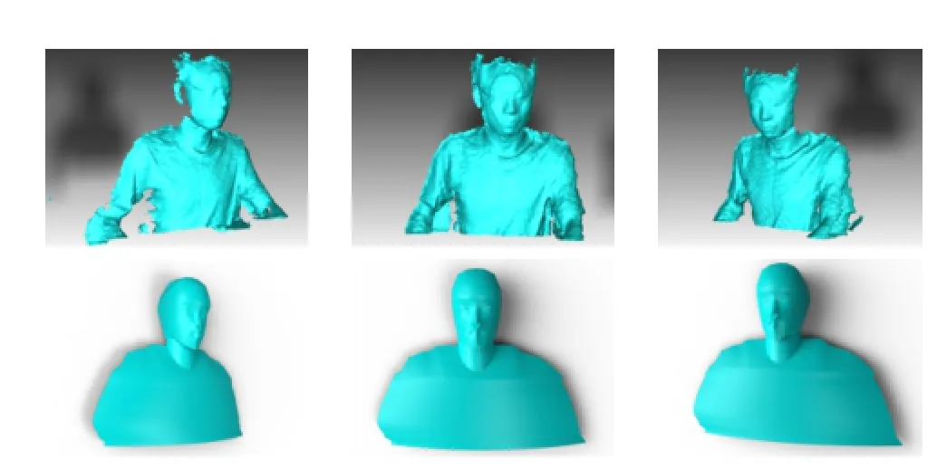
Fig.1 Top:KinectFusion modeling result,from various viewpoints. The model is very noisy and is unsuited to videoconferencing. Bottom:our modeling result.Our smoother parametric model is better suited to videoconferencing.
The main technical contribution of our work,other than a demonstration of the advantages of using motion parallax for videoconferencing,is a practical system for doing so.It is based on a parametric model of the head and shoulders and allows videoconferencing based on commodity hardware.The model can cope with the high levelsof noise in Kinect data,and is lightweight yet sufficiently realistic.Our approach allows our system to be more robust to noise than other generic models,while providing more realistic results than simply layering the foreground and background.
2 Related work
2.1Motion parallax and its application in videoconferencing
Motion parallax is an important kinetic monocular depth cue that provides the visual system with information about the configuration of space and objects in the surrounding physical environment[8]. Motion parallax works by comparing the relative movement of objects in space;e.g.,as a viewer’s head rotates or moves through space,objects further away move quicker in relation to objects that are closer. This allows the viewer to form accurate judgements about both their current position in the world,and also the relative location of objects around them.
Lee[19]devised a system which tracked user’s head position with a Nintendo Wii remote to determine a suitable camera position for a 3D scene in real time.The resulting shift of the digital space in response to user’s head position produces a powerful depth illusion for the viewer,which in Lee’s words “effectively transforms your display into a portal to a virtual environment”.
Apple’s iOS 7 and later operating systems include a motion parallax effect that moves the icons and tabs on the screen very slightly in response to phone or tablet motion from the user[20].This synthetic motion parallax again creates an enhanced feeling of digital space as the layers move separately.
Applying the same kind of depth separation and 3D modeling approach to a videoconferencing application is potentially promising.However,the complexity of modeling objects in depth in a realtime application,and with sufficient quality to be visually believable(including moving facial features),raises complex technical issues.
Harrison and Hudson[14]proposed a pseudo-3D video-conferencing system based on a commodity webcam.They initially capture a background image and then extract the foreground sender in real time during conferencing.The sender and background are layered at different depths,and a virtual camera is put at a 2D position corresponding to the x-y tracked position of the receiver’s head.To overcome imperfections in the edges of the foreground,simple Gaussian bluring is used along the composition boundary.The system provides some motion parallax but is not particularly realistic as it gives the appearance of two planes in relative motion.
Zhang et al.[15]proposed a similar system,using a feature-based face-tracking algorithm to robustly estimate the position and scale of the face.A time-of-flight camera is used to improve the segmentation of background and foreground,and a matting strategy[21]is used to improve the composition result.Although this provides improved accuracy face tracking and higher quality foreground/background composition,there is still a lack of realism due to the planar modeling of the foreground.
Kim et al.[18]described TeleHuman,a cylindrical 3D display portal for life-size human telepresence. Their system relies on 10 Kinects to capture 360◦3D video;each frame contains an image and a depth map.Their system supports both motion parallax and stereoscopy.Nevertheless,as the Kinect depth stream is noisy,the 3D images are of low quality.The cylindrical display and the need for 10 Kinect devices also make it unsuitable for general use in home and office.
Our system provides a 3D model of the sender’s head,and tracks the 3D position of the receiver’s head,and so can generate more realistic motion parallax than these earlier systems.At the same time,it only needs an ordinary 2D display and a single low-cost Kinect camera.
2.2Modeling
2.2.1Parameterized facial models
Many works have considered parameterized face models;CANDIDE-type models are widely used for modeling the human face.These are predefined triangle meshes whose shape can be adjusted by animation units and shape units.The animation unit parameters represent facial expression,while the shape units tailor the proportions of the face to a particular individual.The initial version of CANDIDE[22]contained 75 vertices and 100 triangles.Since the mouth and eyes are crudely represented,this version of the model is unrealistic and so is rarely used.Welsh[23]produced an improved CANDIDE model with 160 vertices and238 triangles,covering the entire frontal head and shoulders.However,using a fixed number of vertices to model the shoulders does not lead to good results.The most popular version,CANDIDE-3[24],provides more details for mouth,cheeks,nose,and eyes,using 113 vertices and 168 triangles. This version is much improved and is used in the Microsoft Kinect SDK.The most obvious drawback of such models is that they only represent the frontal face so look like a mask when rendered. In videoconferencing,this presents problems if the sender turns their head too far to one side.
2.2.2Generic real-time 3D modeling
Making 3D models from data is a fundamental problem in computer graphics and computer vision,with much research.Balancing speed and accuracy is a key issue.Rusinkiewicz et al.[25]pioneered the real-time modeling of objects from depth data. Theirapproachusesa60Hzstructured-light rangefinder;the user rotates an object in front of it to get a continuously-updated model.However this procedure is unsuited to human body capture since any non-rigid movement of the body leads to inaccurate modeling results.While commercial systems exist for dynamic face and body capture,such as those produced by 3dMD[26],they are far too expensive for home and office use.Based on the much lower-priced Kinect,KinectFusion[16,17]provides a real-time,robust,room scale GPU-based modeling technique,as part of the Microsoft Kinect SDK.It uses a volume representation in which each voxel contains color information.Models can be updated at an interactive rate.By providing a human body detection module in the Microsoft Kinect SDK,KinectFusion can reconstruct the body even in the presence of non-rigid movement. However KinectFusion has two obvious drawbacks. Firstly,it is memory intensive.Chen et al.[27]showed how to use a fast and compact hierarchical GPU data structure instead of a regular 3D voxel grid to save an order of magnitude of memory. Secondly,the modeling result is noisy,mainly due to the noisy depth data provided by the Kinect itself. This could be overcome to some extent by hardware improvements.
In our low-cost system,we use a parameterized approach to model the body,which is robust,fast,and provides good quality.It can model more of the body than CANDIDE-type approaches,but with much lower noise than approaches that directly use KinectFusion.
3 System overview
Oursystemisintendedforone-to-onevideoconferencing.We assume the users are indoors and the background is static.The hardware needed by our system is cheap and readily available,comprising a Kinect,a commodity PC,and a standard 2D display for each participant.When our system is started,it initially models the background(at each end)while the sender stands to one side,outside the view of the Kinect.A 2D background image is captured,and is texture mapped to a plane whose depth is set to the average distance of the depth image.Our justification for using such a simple model for the background is that the users of a videoconferencing system spend nearly all of their time looking at the other person,and only peripherally observe the background.An alternative approach to prior background capture would be to use an image completion approach[28]to fill background gaps resulting from foreground movement.Apart from the extra computational effort needed,a further disadvantage is that such completed backgrounds always have undesirable artifacts in practice.Since the background is static,it only needs to be transmitted once at the start of the session.
After background capture,the user then sits in front of the system,which builds a model of the front of his or her head,neck,and shoulders in real time;at this stage the user should also turn his head to the left and right to allow modeling of the sides of the head.Since the Kinect is located above the top of the display,it can also capture much of the top of the head.We assume that the bottom part of the head(under the chin)always remains unseen,and that users do not significantly tilt their heads up and down.The user is given feedback in real time to allow verification that the constructed model is satisfactory.The model we produce is a 3D mesh model with a corresponding image texture:the color image provided by the Kinect is mapped via texture coordinates to the 3D vertices of the mesh model.
After model acquisition is finished,the two users are then connected to each other.The backgroundmodel is transmitted first.After that,real-time transmission of the foreground model is sent for each frame.In particular,the location of each mesh vertex and its texture coordinates are sent,together with the current texture image.While the connection is active,each receiver sees the sender as a rendered 3D model,rendered according to the receiver’s viewpoint.Thus,as the receiver’s head moves,the viewpoint used for rendering changes,and the resulting motion parallax and 3D modeling give the receiver a sense of 3D.We illustrate our system in Fig.2.
Subsequent sections now give further details: Section 4 discusses our parameterized model of the upper part of the human body,while Section 5 explains how we construct the virtual scene.We evaluate our system in Section 6 and conclude our work in Section 7.
4 Real-time modeling of the upper part of the body
For videoconferencing,we wish to model the upper part of the body,including the head,neck,and the shoulders.During videoconferencing,the front of the head always faces the camera,so this is modeled separately in greater detail.Looking down from above,this frontal model encompasses 180◦as seen from the front.Horizontal movement and rotation of the head may occur.Thus,we must also model the sides and back of the head,which we do using separate low-detail models for the left-back and right-back.These left and right back parts each provide a further 90◦to provide a 360◦head model. The top of different parts of the head is modeled along with each of these three parts(we assume vertical movement does not in practice occur).
For the front of the head,we use the CANDIDE-3 model based on parameters representing individual shape and facial expression.A mesh model based on a quarter ellipsoid,but which does not allow for changes in expression,is used for each of the left-back and right-back of the head.These are joined with appropriate continuity to the front of the head and each other to complete the head.Further similar expressionless models are used for the neck and shoulders.Each model is based on a standard template,appropriately deformed to suit a particular individual,with further transformations that may represent rotation and translation.The position and orientation of the model are continuously updated to capture the movement of the user.
The model parameters are of two types,those that are constant for an individual,and those that vary from frame to frame(e.g.,representing facial expression).Thus our model building process extractsindividualbodyfeaturesinaninitial step before the conversation begins,to determine the parameters describing the body shape of a particular person.The textures of the left-back and right-back head are also captured at this stage,and are transmitted with the texture coordinates of the corresponding vertices just once at the start of the session-these are assumed to be relatively unimportant and can be considered to be unchanging.Then as the conversation occurs,feature tracking is used to acquire the dynamic parameters.The textures for the front of the head,neck,and shoulders are also captured for each frame to allow for changes in expression and hence facial appearance,as well as for minor body movements.The vertex positions of the head,neck,and shoulders,their texture coordinates,and the current image are transmitted for each frame.
4.1The parameterized model
We now consider the models in more detail.The front,left-back,and right-back of the head are modeled separately and seamlessly joined together. The upper end of the neck is inserted into the head while the lower end of the neck is inserted into the shoulders,connecting the three parts as a whole.

Fig.2 System overview.
4.1.1The head
The head model comprises three parts:front,leftback,and right-back.The frontal head uses the CANDIDE-3 model[24],which can be written as
where Mfhrepresents the 3D model of the frontal face in terms of a 3N-dimensional vector containing the(x,y,z)coordinates of the vertices(h denotes head,f denotes front).Sfis a predefined standard face model,representing standard positions on a standard face,connected into a triangulation with known topology.σ deforms the standard face to match a specific face,and is derived from the shape units describing a particular individual’s face,e.g.,the height of the head and the width of the chin.A encapsulates animation units(AUs),which describe expression changes from a neutral facial expression. Note that σ is invariant over time but A varies.R is a rotation matrix and t is a translation to allow for head movements.
The left-back of the head is defined as
where Slis a predefined left-back of the head model,containing 3 triangle strips making an arched shape;each strip has 9 vertices in total.We do not model the shape of the ears as they typically occupy a tiny area in videoconferencing,and furthermore their geometry is complicated and hard to model robustly. Texture mapping to a curved surface suffices for our application.ω deforms the template to a specific head.We illustrate the left-back of the head model in Fig.3(a).The right-back of the head model is symmetrically defined as
To seamlessly connect the different parts of the head model we ensure that appropriate triangles in each part share vertices.In reality,these parts of the head undergo only very limited deformation due to changes in expression,and for simplicity in this application we assume they are rigid.
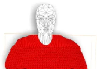
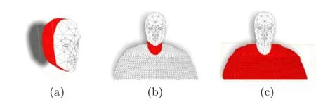
Fig.3 Parameterized models:(a)left-back of the head,(b)neck,(c)shoulders.
Thus,the parameters for the head model are of two kinds,unchanging ones specific to an individual: {σ,ω},and those which depend on head pose and facial expression:{A,R,t}.
4.1.2The neck
The neck occupies a relatively small area of the field of view,and is not the focus of attention.Thus,it suffices to model it using a single triangle strip:

where Snis a triangle strip forming a forward facing semi-cylinder,andµis a deformation to match a particular individual.We assume that even if the head rotates,the neck more or less remains fixed,so we need not add a rotation term for the neck model. Figure 3(b)illustrates a deformed neck model.
Thus,the parameters for the neck model are of two kinds,unchanging one specific to an individual:µ,and that which depends on neck position:t.
4.1.3The shoulders
The shoulders(and associated part of the chest)are more difficult to model than the head and the neck.Unlike the head,they have no stable feature points,making it harder to define a template based on feature points.The shoulders occupy a much larger part of the image than the neck,and their shape varies significantly between different individuals.We also note that human observers are more sensitive to the shape of the shoulders than to their texture or appearance.Our main goal in modeling the shoulders is to smoothly approximate their silhouette.We thus define them as where Ssis a standard shoulder template.

To form the shoulder template,we first define edge vertices.These are divided into two sets,those lying on the more or less vertical sides of the shoulders(i.e.,the arms),and those lying on the more or less horizontal top of the shoulders.See Fig.4:“vertical”edge vertices are marked with triangles and“horizontal”points are marked with stars.The vertical edge vertices are used to separate the shoulder model into layers;left and right vertical vertices sharing the same y value are connected by a curve.To define this curve,we add another auxiliary vertex with the same y value and whose x coordinate is the average of their x coordinates.Itsz coordinate is closer to the viewer by a distance of 1.2 times the radius of the neck.These three vertices determine a circular arc,which is uniformly sampled by Nvvertices(Nv=40 in our implementation). Horizontal vertices share the same z values as the vertical edge vertices,and are connected to the first layer of vertical edge vertices,as illustrated in Fig.3(c).α and β are deformations in vertical and horizontal directions respectively which we explain later.tsis the translation of the shoulders.Thus,the parameters for the shoulder model are of two kinds,unchanging ones specific to an individual:{α,β},and that which depends on shoulder position:ts.
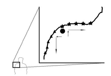
Fig.4 Shoulder edge point detection.The black circle is the corner point found after several iterations.It is then snapped to the vertical edge and vertical edge points(triangles)are detected by downwards search.After horizontal snapping,horizontal edge points(stars)are detected by horizontal search.
4.2Parameter determination
We now explain how we determine the various parameters.The overall set of parameters describing the model is
Theseparametersfallintotwocategories: {σ,ω,α,β,µ}are unchanging in time and describe the body shape of an individual,while{R,t,ts,A}change over time,describing expression,position,and orientation.
4.2.1Offline parameter calculation
We initially determine each of the unchanging parameters.σ can be calculated from the 11 shape units as explained in Ref.[24],while ω can be calculated from the distance between the cheek bone and the ear;the necessary information in both cases can be obtained using the Kinect SDK.µcan be calculated from the width and height of the neck. We approximate the width of the neck as the x distance between the left/right jawbone points of the face provided by the Kinect SDK:such feature points of the face provide a more stable solution than determining the neck location from the 2D image.The length of the neck is determined as the y distance between the skeleton joint of the head and the center of the shoulders,provided by the Kinect skeleton stream.α and β can be calculated from the vertical and horizontal edge points on the shoulders,respectively.α comes from corresponding pairs of vertical edge vertices,which define a deformation for each horizontal strip.β defines how horizontal edge vertices are translated from an initial position to their current position.
4.2.2Online parameter calculation
Duringreal-timetransmission, thechanging parameters must be determined.A can be calculated using the MPEG-4 face animation parameters,again provided by the Kinect SDK.R and t can be straightforwardly calculated from the face tracking output also provided by the Kinect SDK.To determine ts,we average all x centers of vertical edge vertex pairs,and the y centers of all horizontal edge vertex pairs.Finding these edge vertices depends on fast and robust edge point extraction. Our approach is based on edge point detection and edge point filtering,which are further explained.
4.2.3Edge point detection
First,we must search for the shoulder edge points. The Kinect provides three different data streams: a color stream,a depth stream,and a skeleton stream.The skeleton stream provides robust tracking information for twenty joints of the user’s body. We use the left and right shoulder joints as initial shoulder corner points at which we switch from horizontal to vertical edge points.
Since the Kinect depth stream is noisy,we do not perform the search on the depth image.Instead,we make use of player ID information also contained in the depth stream.Each pixel is allocated a positive number indicating the player ID if this pixel belongs to a person,or 0 if this pixel is outside any person. As the player ID image is less noisy than the depth image(see Fig.5),we use the player ID information to determine which pixels belong to the sender.
Starting from the initial corner points,we first search for more accurate shoulder corner points,located on the person’s outline,and then find vertical and horizontal edge points.An iterative approach is used to find the accurate corner points.Starting from the initial left corner point,we find the first pixel going vertically upwards that is outside the person;we also perform a similar horizontal search from right to left.The midpoint of the 2 pixels found gives a more accurate corner point.This process is repeated until the distance between the two points is under than 2 pixels.
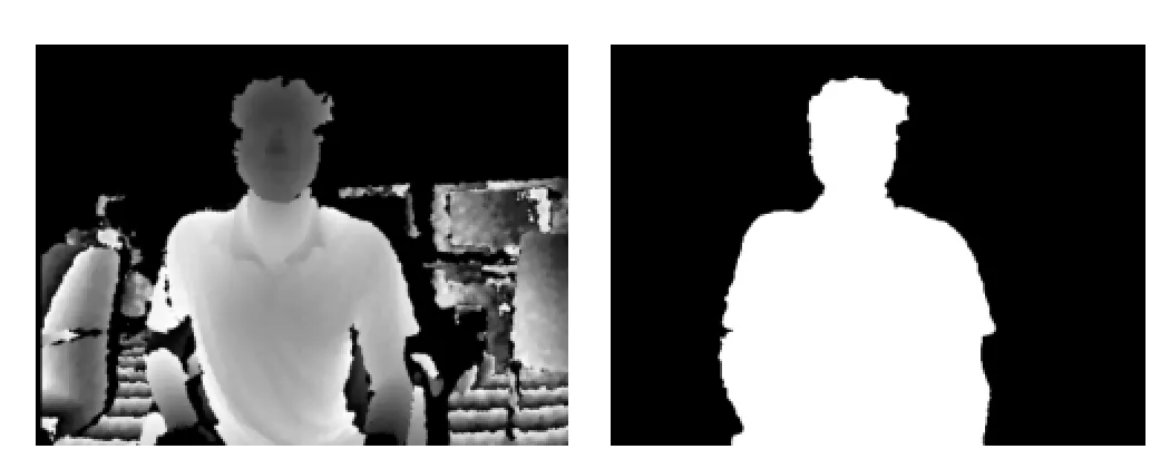
Fig.5 Raw depth data and player ID data.
Using this accurate corner point we follow the edge downwards to find successive vertical edge points until reaching the bottom of the frame.For horizontal edge points,we search from the corner rightwards until reaching the neck.We consider the neck to start when the edge slope exceeds 45◦.Edge points are sampled 5 pixels apart.
4.2.4Edge point filtering
We next stabilize this edge point data.We have two sets of vertical and horizontal edge points(one on either side of the body).As these have been determined from player ID data that still has a somewhat noisy boundary,we need to smooth them both within each individual frame,and in between frames.Within each frame,each row and column of points is filtered using a Gaussian filter with radius 4 pixels.To help alleviate jitter in the player ID image,we calculate the average position for each row and column of points,and if the change between frame i+1 and frame i is more than 5 times the change between frames i and i-1,we regard the frame i+1 as having significant jitter,and keep the positions of the points unchanged from frame i.Within a frame,if the change in any one row(or column)is more than twice as big as that of its neighbours,we again assume this is due to jitter and keep the positions of these two rows the same as in the previous frame.
4.3Model part connection
The parameter values and standard models provide a description for each part.We next need to consider how to connect them into a whole.
Itiscommontoaddgeometricconstrains when assembling parts to make a model[29-32].These approaches usually optimize an energy function which satisfies connectivity constraints,while ensuring the positions of the vertices after optimizationhavetexturecoordinatesasclose as possible to the correct ones.Concentricity,coplanarity,parallelism,etc.are commonly used constraints,and are useful for such things as mechanical parts,but are not particularly useful fororganicobjectssuchasthehumanbody. This has many non-rigidly deformable parts whose connections can be hard to precisely define.
Instead,we opt for a simpler approach,and add softer geometric constraints.We only adjust the z values of the head and shoulders,and z and y values for the neck.Three principles are used to provide a simple modeling approach:
•Boundary vertices of the shoulders all share the same z value,and are located on the same plane as the edges of the semi-cylindrical neck.
•The(vertical)axis of the neck semi-cylinder has the same z value as the midpoint of the left and right jawbones.
•Since the neck is thinner than the head and shoulders,and behind them,it can be made a little longer(at both ends)than it is in reality,as a way of ensuring connectivity. To meet these requirements,we determine the z depth of the head first,based on the depth values. Then we adjust the depths of the neck and shoulders,according to the first two principles above.Next,we connect the top two vertices on the back of the neck to two key points on the head located under the ears. No special steps are needed to join the neck and the shoulders due to the extra length of the neck;the shoulders cover its end.This simple approach avoids solving any optimization problem and is very fast.
5 Scene rendering
We now consider how the scene is rendered on the receiver’s side.
At setup time,the background texture image,the background model and its texture,and texture images of the left-back and right-back head aretransmitted to the receiver just once.
During videoconferencing,the color image of each frame is sent as a texture image together with the foreground model as triangle meshes and vertex texture coordinates.The resolution of the color image is 640×480,with 8 bits per channel.The frame rate of our system is 30 fps.The color information is sent using a video codec,while typically the foreground model has fewer than 1000 vertices,which requires little extra bandwidth over that needed by the color stream.
On the receiver’s side,the head of the receiver is tracked during model building and the received scene models are rendered taking into account the position and orientation of the tracked head.Our goal is to give the receiver a realistic impression of parallax.Our basis for rendering is that the receiver’s attention is assumed to be fixed on the sender’s face,at the midpoint of sender’s eyes.Thus,we render the scene so that the sender appears at a fixed location on the screen.Most of the parallax is seen in the relative motion of the background;slight changes to the sender’s appearance are also seen as the receiver moves the head relative to the position of the sender’s head-as the receiver moves more to one side,more that side of the sender’s head will be seen.Detailed rendering parameters are determined according to the position of the receiver’s head,using a predetermined scene layout which simulates real face-to-face communication.We now give the details.
5.1Scene layout
We must consider two problems when arranging thescenetoberendered.Thefirstisthat positions of models transmitted to the receiver’s side are determined by the relative positions of the sender’s Kinect and the sender.Suppose the distance between the Kinect and the foreground and background on the sender’s side are Dfand Dbrespectively.Since the simulated distance between the receiver and the sender is arbitrary,we simply assume that the receiver sits at the position of the Kinect on the sender’s side.Suppose the rendering distance between the receiver and the sender is df,and that between the receiver and the sender’s background is db,we thus have:
However,the receiver may move backwards and forwards to a limited extent.Moving backwards would cause the receiver to see unmodeled parts of the sender’s scene,losing realism.To prevent this problem arising,we slightly reduce the angle of view relative to the sender’s side.If the angle of view at the sender’s side is ψsand is ψrat the receiver’s side,we set ψrto

In our implementation we set ψsto 45◦and ρ to 0.9.
5.2Camera position
We assume that the receiver’s gaze is fixed at the midpoint of the sender’s eyes.If the receiver always accordingly rotated his head in compensation while moving it,it would be straightforward to perform rendering based on this new viewing position and direction,using the head tracking information.In practice,however,the receiver may often just rotate his eyes as he moves his head,and such eye movement cannot be readily determined.Thus,rather than using the measured rotation of the head as a basis for rendering,for simplicity we model the situation as if his eyes were fixed in his head to look forwards,and work out how much he would have to rotate his head to keep looking at the same point.
Thus,we separate the movement of the receiver’s head into two parts:translation,and consequent head rotation.The tracked midpoint of the receiver’s eyes provides changes in position.For each frame,the change in position relative to the previous frame,is used to update the camera position.Camera rotation based on modeled head rotation is assumed to occur in two orthogonal directions,through small angles θ about the y axis and ϕ about the x axis. If the distance between the camera and the sender along the z axis is Ds,and the offsets relative to the original locations in x and y directions are Dxand Dyrespectively,the changes in rotation angles are simply given by
The camera position and orientation are accordingly updated in each frame.
6 Experiments and evaluation
Our system has been implemented in C#using the Microsoft Kinect SDK v1.8,on a PC with an Intel Core i7 3770 3.40GHz CPU,an Nvidia GTX780GPU,and a first generation Kinect.We illustrate the results of our system in Fig.6.
We have performed an initial user study;a much fuller and more carefully designed perceptual study is also planned.We invited 10 participants to take part in the user study;they were Ph.D.students in computer graphics and computer vision,whose background might perhaps make them more critical than the general public.Each participant took part in videoconferencing using our system,and using Microsoft Skype as a typical 2D videoconferencing system as a basis for comparison.
We were interested in particular in how much our system gave an enhanced impression of depth during videoconferencing.We thus specifically asked them to evaluate their experience of depth when using our system compared to the typical 2D videoconferencing system.Five subjective scores could be chosen,ranging from-2 to+2,where-2 meant our system gave much less sensation of depth,-1 meant somewhat less sensation of depth,0 meant both systems gave more or less equal sensations of depth,+1 meant our system gave somewhat more sensation of depth,and+2 meant much more sensation of depth.Furthermore,to achieve further insight,we asked participants to give a short written comment justifying their evaluation.
Eight out of the ten participants gave our system a score of 2,while two of them gave a score of 1.These initial results clearly show that our approach leads to a greater sensation of depth during videoconferencing.Of the two participants who gave a score of 1,one of them justified his score on the basis that the background seemed like a flat plane,when the subject could see it was actually composed of two orthogonal walls.The other participant who gave a lower score said the edge of the head did not seem sufficiently smooth,and the lack of realism caused him to keep looking at the edge,distracting him.Since we made the assumption that the receiver would fixate at the midpoint of the sender’s eyes,staring at the edge of the sender violates the assumption,perhaps leading to the lessthan-perfect satisfaction with the depth realism.
These comments will be used to inform future improvements of our system,along with those for the eight participants who gave the highest score. Their most frequent comments can be summarized as“I observed the motion parallax between the foreground and background”and“the perspective of the scene is very consistent with my viewpoint”.
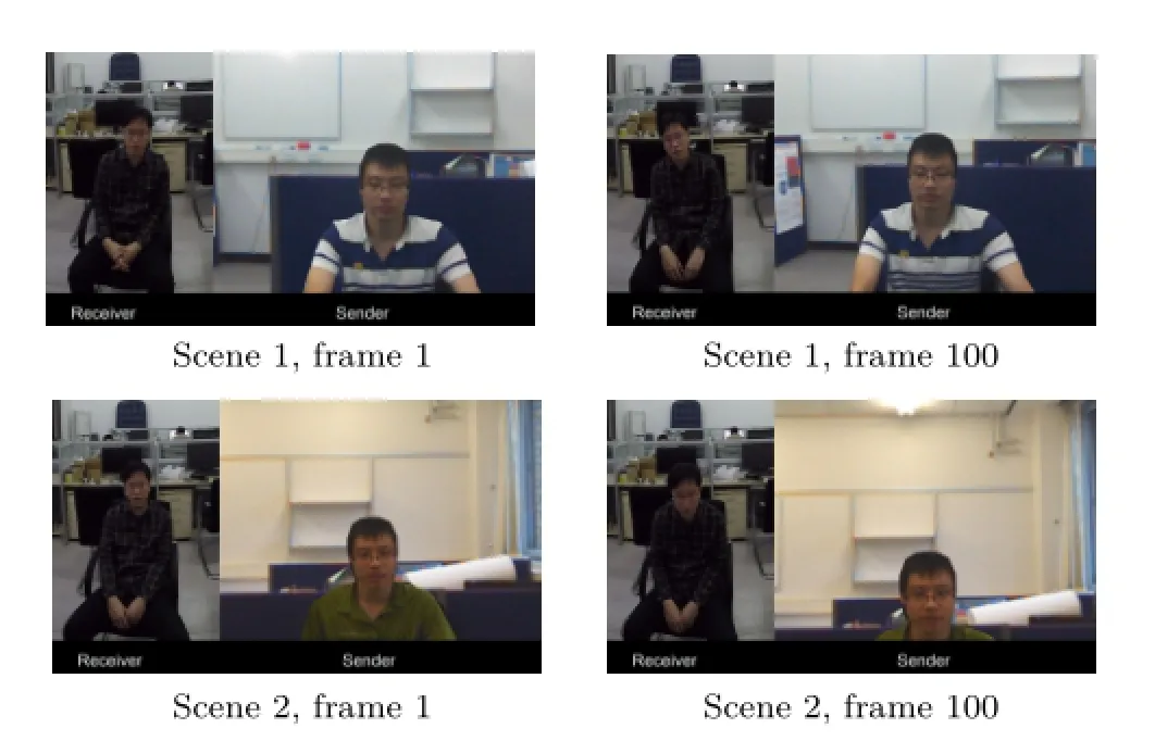
Fig.6 Four frames were selected from 2 scenes.In scene 1,the receiver tilted his head to the left in frame 1 while in frame 100 he tilted his head to the right.The viewpoints for rendering the sender’s scene were changed with respect to the head’s position.In scene 2,the receiver sat straightly in frame 1 while in frame 100 he leaned forward.
7 Conclusions
In this paper,we proposed a videoconferencing system based on 3D modeling and motion parallax to give an improved sensation of depth.We use a parameterized model of the sender,and position a synthetic camera based on tracking the receiver’s head position.Initial experimental results show that users feel that our system gives a greater sensation of depth perception than a typical 2D videoconferencing system.Further,fuller perceptual testing is planned for the future.
Our system has some limitations.Our system does not support hand gestures or large movements,e.g.,standing up or large shoulder rotations,as these are harder to track and would need more complete models.Our system assumes there is only one person in the field of view-the Kinect depth stream is noisier when there are multiple persons,and this makes it hard to give a visual-pleasing modeling result.
We hope to improve our system in the future by using a more detailed model of the sender based on more vertices;newer Kinect-like devices will also help to make improved models.We will also make more complex models of the background;this can be done readily,even if a little slow,as part of theoffline modeling before videoconferencing begins.
Acknowledgements
This work was supported by the National HightechR&DProgramofChina(ProjectNo. 2013AA013903), theNationalNaturalScience Foundation of China(Project Nos.61133008 and 61272226),ResearchGrantofBeijingHigher Institution Engineering Research Center,an EPSRC Travel Grant,and the Research and Enterprise Investment Fund of Cardiff Metropolitan University.
References
[1]Rosenthal,A.H.Two-way television communication unit.US Patent 2420198,1947.
[2]Okada,K.-I.;Maeda,F.;Ichikawaa,Y.;Matsushita,Y.Multiparty videoconferencing at virtual social distance:MAJIC design.In:Proceedings of ACM ConferenceonComputerSupportedCooperative Work,385-393,1994.
[3]Sellen,A.;Buxton,B.;Arnott,J.Using spatial cues to improve videoconferencing.In:Proceedings of the SIGCHI Conference on Human Factors in Computing Systems,651-652,1992.
[4]Tang,J.C.; Minneman,S.VideoWhiteboard: Video shadows to support remote collaboration.In: Proceedings of the SIGCHI Conference on Human Factors in Computing Systems,315-322,1991.
[5]Vertegaal, R.TheGAZEgroupwaresystem: Mediatingjointattentioninmultiparty communication and collaboration.In:Proceedings of the SIGCHI Conference on Human Factors in Computing Systems,294-301,1999.
[6]Vertegaal,R.;Ding,Y.Explaining effects of eye gaze on mediated group conversations:Amount or synchronization?In:Proceedings of ACM Conference on Computer Supported Cooperative Work,41-48,2002.
[7]Pirenne,M.H.Optics,Painting and Photography. Cambridge,UK:Cambridge University Press,1970.
[8]Solso,R.L.Cognition and the Visual Arts.Cambridge,MA,USA:MIT Press,1996.
[9]Pepperell,R.;Haertel,M.Do artists use linear perspective to depict visual space?Perception Vol. 43,No.5,395-416,2014.
[10]Baldwin,J.;Burleigh,A.;Pepperell,R.Comparing artistic and geometrical perspective depictions of space in the visual field.i-Perception Vol.5,No.6,536-547,2014.
[11]Kemp,M.The Science of Art:Optical Themes in Western Art from Brunelleschi to Seurat.New Haven,CT,USA:Yale University Press,1990.
[12]Kingslake,R.Optics in Photography.Bellingham,WA,USA:SPIE Publications,1992.
[13]Ogle,K.N.Research in Binocular Vision,2nd edn. New York:Hafner Publishing Company,1964.
[14]Harrison,C.;Hudson,S.E.Pseudo-3Dvideo conferencing with a generic webcam.In:Proceedings ofthe10thIEEEInternationalSymposiumon Multimedia,236-241,2008.
[15]Zhang,C.; Yin,Z.; Florencio,D.Improving depthperceptionwithmotionparallaxandits application in teleconferencing.In:Proceedings of IEEE International Workshop on Multimedia Signal Processing,1-6,2009.
[16]Izadi,S.;Kim,D.;Hilliges,O.;Molyneaux,D.;Newcombe,R.;Kohli,P.;Shotton,J.;Hodges,S.;Freeman,D.;Davison,A.;Fitzgibbon,A. KinectFusion:Real-time3Dreconstructionand interactionusingamovingdepthcamera.In: Proceedings of the 24th Annual ACM Symposium on User Interface Software and Technology,559-568,2011.
[17]Newcombe,R.A.;Izadi,S.;Hilliges,O.;Molyneaux,D.;Kim,D.;Davison,A.J.;Kohli,P.;Shotton,J.;Hodges,S.;Fitzgibbon,A.KinectFusion:Real-time dense surface mapping and tracking.In:Proceedings of the 10th IEEE International Symposium on Mixed and Augmented Reality,127-136,2011.
[18]Kim,K.;Bolton,J.;Girouard,A.;Cooperstock,J.;Vertegaal,R.TeleHuman:Effects of 3D perspective on gaze and pose estimation with a life-size cylindrical telepresence pod.In:Proceedings of the SIGCHI Conference on Human Factors in Computing Systems,2531-2540,2012.
[19]Lee,J.C.Head tracking for desktop VR displays using the Wii remote.Available at http://johnnylee.net/ projects/wii/.
[20]iPhone User Guide For iOS 8.1 Software.Apple Inc.,2014.
[21]Levin,A.;Lischinski,D.;Weiss,Y.A closed form solution to natural image matting.IEEE Transactions on Pattern Analysis and Machine Intelligence Vol.30,No.2,228-242,2008.
[22]Rydfalk,M.CANDIDE,aparameterizedface. TechnicalReportLiTH-ISY-I-866.Link¨oping University,1987.
[23]Welsh,B.Model-based coding of images.Ph.D.Thesis. British Telecom Research Lab,1991.
[24]Ahlberg,J.CANDIDE-3—An updated parameterised face.Technical Report LiTH-ISY-R-2326.Link¨oping University,2001.
[25]Rusinkiewicz,S.;Hall-Holt,O.;Levoy,M.Real-time 3D model acquisition.ACM Transactions on Graphics Vol.21,No.3,438-446,2002.
[26]3dMD Static Systems.Available at http://www.3dmd. com/3dMD-systems/.
[27]Chen,J.;Bautembach,D.;Izadi,S.Scalable real-time volumetric surface reconstruction.ACM Transactions on Graphics Vol.32,No.4,Article No.113,2013.
[28]Wexler,Y.;Shechtman,E.;Irani,M.Space-time completion of video.IEEE Transactions on Pattern Analysis and Machine Intelligence Vol.29,No.3,463-476,2007.
[29]Chen,T.;Zhu,Z.;Shamir,A.;Hu,S.-M.;Cohen-Or,D.3-Sweep:Extracting editable objects from a single photo.ACM Transactions on Graphics Vol.32,No.6,Article No.195,2013.
[30]Gal,R.;Sorkine,O.;Mitra,N.J.;Cohen-Or,D.iWIRES:An analyze-and-edit approach to shape manipulation.ACM Transactions on Graphics Vol.28,No.3,Article No.33,2009.
[31]Schulz,A.;Shamir,A.;Levin,D.I.W.;Sitthi-amorn,P.;Matusik,W.Design and fabrication by example. ACM Transactions on Graphics Vol.33,No.4,Article No.62,2014.
[32]Zheng,Y.;Fu,H.;Cohen-Or,D.;Au,O.K.-C.;Tai,C.-L.Component-wise controllers for structurepreserving shape manipulation.Computer Graphics Forum Vol.30,No.2,563-572,2011.
ZheZhu is a Ph.D.candidate in the Department of Computer Science and Technology,Tsinghua University. He received his bachelor degree from Wuhan University in 2011.His research interestsarecomputervisionand computer graphics.

RalphR.Martiniscurrentlya professor at Cardiff University.He obtainedhisPh.D.degreein1983 fromCambridgeUniversity.Hehas published more than 250 papers and 14 books,covering such topics as solid and surface modeling,intelligent sketch input, geometricreasoning, reverse engineering,and various aspects of computer graphics. He is a Fellow of the Learned Society of Wales,the Institute of Mathematics and its Applications,and the British Computer Society.He is on the editorial boards of Computer-Aided Design,Computer Aided Geometric Design,GeometricModels,theInternationalJournal ofShapeModeling,CADandApplications,andthe InternationalJournalofCADCAM.Hewasrecently awarded a Friendship Award,China’s highest honor for foreigners.
Robert Pepperell is an artist who studied at the Slade School of Art,London,andhasexhibitedwidely. He has published several books and numerous academic papers,and is a professor of fine art at Cardiff School of Art&Design in the UK.He specialises in research that combines art practice with scientific experimentation and philosophical inquiry.
Alistair Burleigh has a background in the conception and development of new creative digital ideas and technology for commercial application.He studied fine art:interactive media at Newport School of Art and went on to work in lead roles on creative digital projects for a wide range of functions and prestige clients on a global basis.He is now a researcher and technical director working at Cardiff School of Art&Design,UK.
Open AccessThe articles published in this journal aredistributedunderthetermsoftheCreative Commons Attribution 4.0 International License(http:// creativecommons.org/licenses/by/4.0/), whichpermits unrestricted use,distribution,and reproduction in any medium,provided you give appropriate credit to the original author(s)and the source,provide a link to the Creative Commons license,and indicate if changes were made.
Other papers from this open access journal are available free of charge from http://www.springer.com/journal/41095. To submit a manuscript,please go to https://www. editorialmanager.com/cvmj.
杂志排行

Computational Visual Media的其它文章
- Fitting quadrics with a Bayesian prior
- Efficient and robust strain limiting and treatment of simultaneous collisions with semidefinite programming
- Rethinking random Hough Forests for video database indexing and pattern search
- Learning multi-kernel multi-view canonical correlations for image recognition
- A surgical simulation system for predicting facial soft tissue deformation
- Accurate disparity estimation in light field using ground control points