A surgical simulation system for predicting facial soft tissue deformation
2016-07-19XiaodongTangJixiangGuoPengLiandJianchengLvcTheAuthor06ThisarticleispublishedwithopenaccessatSpringerlinkcom
Xiaodong Tang,Jixiang Guo(),Peng Li,and Jiancheng Lv?cThe Author(s)06.This article is published with open access at Springerlink.com
Research Article
A surgical simulation system for predicting facial soft tissue deformation
Xiaodong Tang1,Jixiang Guo1(),Peng Li2,and Jiancheng Lv1
?cThe Author(s)2016.This article is published with open access at Springerlink.com
AbstractIn the field of cranio-maxillofacial(CMF)surgery,surgical simulation is becoming a very powerful tool to plan surgery and simulate surgical results before actually performing a CMF surgical procedure. Reliable prediction of facial soft tissue changes is in particular essential for better preparation and to shorten the time taken for the operation.This paper presents a surgical simulation system to predict facial soft tissue changes caused by the movement of bone segments during CMF surgery.Two experiments were designed to test the feasibility of this simulation system.The test results demonstrate the feasibility of fast and good prediction of post-operative facial appearance,with texture.Our surgical simulation system is applicable to computer-assisted CMF surgery.
Keywords cranio-maxillofacial(CMF)surgery;finite element model(FEM);soft tissue;modelview-controller
1Machine Intelligence Lab,Sichuan University,Chengdu 610065,China.E-mail:X.Tang,xiaodong3.14@163. com; J .Guo,guojixiang@scu.edu.cn (); J .Lv,lvjiancheng@scu.edu.cn.
2West China College of Stomatology,Sichuan University,Chengdu 610065,China.E-mail:lipengfly11@163.com. Manuscript received:2016-01-11;accepted:2016-02-23
1 Introduction
With the development of techniques in computerassistedorthognathicsurgery,researchinto craniofacialmorphologyandmodelsofbone and soft tissue have played an important role in maxillo-craniofacial therapy[1].3D reconstruction of bone and soft tissues,quantitative measurements,andvirtualsurgicalsimulationresultsprovide significantunderpinningstooptimizesurgical programs.Predictionofnewfacialappearance is particularly important.Without any risk to patients,surgeons can operate on a patient virtually until an aesthetically satisfactory result is obtained. Therefore,building a precise prediction system for facial soft tissue deformation is very important and useful.
In this paper,we describe a simulation system for facial soft tissue prediction which is based on the linear finite element method.The simulation system can be used by surgeons to obtain an estimate of facial appearance.Our work utilizes individual patient data for both skull and skin surfaces to build the deformation model.The data needed can be acquired from 3D photography and 3D computed tomography(CT).To represent facial soft tissue deformation given the movement of bone structures,we build a correspondence between a face mesh and a bone mesh.Our facial models are composed of tetrahedral elements to permit finite element analysis.Facial tissue changes caused by bone movement can be well simulated.
The remainder of this paper is organized as follows.In Section 2,we present related research and underlying technologies related to our proposed method.We briefly review the principle of the linear elasticity finite element model(FEM)algorithm in Section 3.We then describe in detail in Section 4 our method for building the deformation model and the functions of each module in the deformation prediction pipeline.In Section 5,we report test results obtained with our system,showing that our approach is feasible.Finally,in Section 6,we conclude our work and discuss possible future improvements.
2 Related work
In the early 1980s,the prediction of post-operativefacial appearance was initiated.Some research[2]presented the idea of predicting soft tissue changes due to bone movement by combining bone structure models together with soft tissue models.Mass springmodels(MSM)wereoriginallyusedto predict the soft tissue behavior.They originated in computer animation and could achieve real-time effects,but are considered to be rather inaccurate when precise modeling of physiological behavior is required.Finite element models(FEM)provide another popular method to simulate facial soft tissue deformation.This is an accurate approach to simulating the mechanical and physiological characteristicsofsofttissue,butitismore computationally expensive[3].Keeve et al.[4]compared these two most popular soft tissue models for maxillofacial surgery.They concluded that FEM could be superior to MSM for biomechanically accuracy,but inferior in terms of speed and sample architecture.
Koch et al.[5]proposed an approach to simulate soft tissue changes arising because of realignment of underlying bone structure.However,their methods were not integrated into a surgical simulation system. Maciel et al.[6]designed a system for surgical simulation.However,their attempts focused on the interactions between the user and the computer. Due to the high efficiency requirements,most commercial software products for predicting facial soft tissue deformations for maxillofacial surgery planning are based on statistical strategies.However,the prediction accuracy depends on the number of patient samples involved.Among these strategies,physically based methods can simulate soft tissue deformation more accurately and realistically.
3 Basic principles of linear FEM
In elasticity theory,the finite element method(FEM)is the most commonly used method to describe the continuous mechanical behavior of soft tissues[7]. This method is based on a volumetric discretization of the structure,using a 3D mesh.For 3D modeling,the most commonly used elements are hexahedra and tetrahedra.In our paper,we use tetrahedra as the mesh elements.
After the FEM discretization,the motion of a deformable tissue can be described by the Euler-Lagrange equation,which is a second order system of ordinary differential equations:

where M ∈R3n×3ndenotes the mass matrix,U ∈R3ndenotes the displacement of the mesh points,˙U denotes the first derivative of the displacement vector,and¨U denotes its second derivativer.fextdenotes the external force(e.g.,a user imposed force,or the force produced by the movement of bone).findenotes the internal force or volume force.The mass matrix M can be pre-computed from the object’s mesh density distribution in the rest state.The damping forces D(U,˙U)are independent of time,and can be represented as

where α and β are Rayleigh damping constants,which are the positive real-valued parameters,which are variable in this system.We use K to denote the tangent stiffness matrix,which can be represented by the Jacobian matrix of the internal forces fin.

For each mesh element,f denotes the internal force acting on it.This satisfies the mechanical equilibrium equations: where σ is the stress tensor.We use u to describe the displacement of the element.From u we can calculate the strain tensor ε ,which describes the deformation per unit area.There are two popular choices in the field of computer graphics,the Green-Lagrange nonlinear strain tensor εG: εG=(∇u+∇uT+∇u×∇uT),and the Cauchy linear strain tensor εC: εC=(∇u+∇uT),where∇u denotes the gradient of the displacement vector u.In a large deformation setup,the Green-Lagrange strain tensor εGcan provide a better result than the Cauchy strain tensor εC,while when the deformation displacements are relatively small,the Cauchy strain tensor εCsuffices to calculate the result accurately. Using the Cauchy linear strain tensor can reduce the computation required.In this paper,we use the Cauchy strain tensorεC.Hooke’s Law states that the stress-strain relationship is linear,σ =Dε ,where:

Fig.1 Pipeline of the facial soft tissue deformation prediction method.
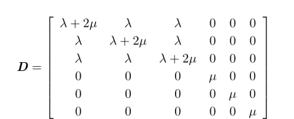
HereλandµareLam´econstantsdirectly proportional to the well-known material properties of Young’s modulus E and Poisson’s ratio v:
4 Framework
Figure 1 shows our deformation prediction pipeline. It includes the following four parts.
•Data preparation.The pre-operative CT scan taken to construct the model of bone structure and the pre-operative 3D photography taken to obtain a textured mesh model of facial surface are input.A mesh generator is used to construct a tetrahedral model for FEM.
•Mapping.This part includes two kinds of meshmapping methods,a surface-mapping method and a bone-mapping method.The deformation result is directly expressed via the skin surface by the surface-mapping method.The bone-mapping method allows simulation of interaction between bone and soft tissue.
•Simulation.The obtained forces are applied to the skin surface,according to the force-transfer principle,to simulate the deformation caused by bone movement.Using suitable boundary conditions for the biomechanical soft tissue model,the new facial appearance is computed using a linear elasticity FEM approach.
•Control and display.The overall control and display structure are based on the model-viewcontroller pattern.
4.1Data preparation
4.1.1Data acquisition
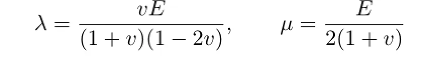
Prior to craniofacial surgery,a pre-operative 3D CT scan and 3D photographs are acquired.The commercial product FaceSCAN3Dis used to obtain a 3D facial mesh,which describes the structure of the surface of the face as well as giving texture information.3D CT scans are widely used as a tool to observe diseased human tissue,and provide excellent visualization of craniofacial tissue.The marching cube algorithm[8]is employed to reconstruct dense,highly detailed bone surface mesh models.The high quality skin surface acquired from the 3D photography(see Fig.2(a))is registered together with the bone structure,ready for simulation.
4.1.2Dividing the intermediate mesh
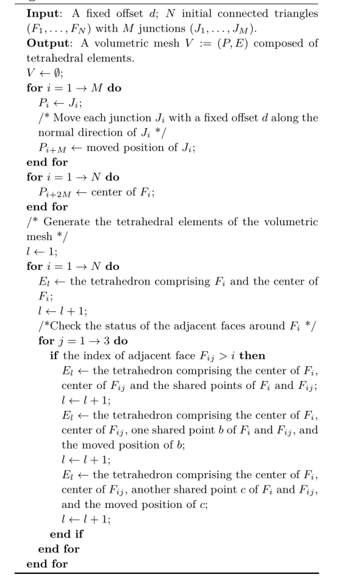
To simulate skin tissue deformation,we need to build a volume mesh data model containing all deforming skin tissues.As volume elements,weuse tetrahedra;these permit a good expression of skin tissue properties.To save processing time and memory usage,we restrict the tetrahedral mesh to the surface region that will deform during surgery,near shifting bones.Our system allows the user to confirm the deformation region near such bones via an intermediate mesh.As shown in Fig.2(b),the green region of the skin surface is chosen as the intermediate mesh.This intermediate mesh is then used to generate the tetrahedral mesh separately,to build the bone-mapping and surface-mapping models.
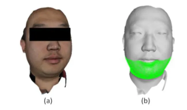
Fig.2(a)A 3D photograph with texture information;(b)the chosen intermediate mesh in the face surface.
4.1.3Generating tetrahedra
Our“STGenerator” algorithmisshownin Algorithm 1;it generates a high quality tetrahedral mesh from the intermediate mesh.The algorithm establishes tetrahedral elements from the surface mesh based on the negative face normal and point normal directions.The algorithm creates new points in certain offset positions along the negative normal directions of the grid points.In the same way,new points can be generated at certain offset positions from the center of each triangle surface along the negative normal direction of the triangle.Then,the algorithm creates tetrahedral elements using the following principles:
•Each triangle determines a tetrahedral element using the offset point of its center,as shown in Fig.3(a).
•Given two adjacent triangles,their common edges determine a tetrahedral element using the offset points of their centers,as shown in Fig.3(b).
•Given two adjacent triangles,the two offset points of their centers separately determine a tetrahedral element using one of their shared points and its offset point,as shown in Fig.3(c).
Fig.3 Three ways of generating tetrahedral elements.
Algorithm 1:A ST Generator
4.2Mapping methods
4.2.1Surface-mapping method
For computational efficiency,the tetrahedral mesh used for simulation is restricted to the surface region near shifting bones.Thus,the tetrahedral mesh containing all facial tissues is unsuitable forclinical validation.Moreover,since the perception of the human face is mainly determined by the relationships between different parts of the face,it is important for surgeons to see the whole face when inspecting the effect of a maxillofacial procedure,not just a part of it.To combine the advantages of a smooth tetrahedral mesh for fast simulation and a realistic,highly detailed mesh with texture information for a good recognition,a surface-mapping method is used.The corresponding relationship between the intermediate mesh and the complete facial mesh is built by preserving the indices of vertices in the intermediate mesh in the surface-mapping method.In particular,the displacement vector of the intermediate mesh can be transformed to the facial grid by using the index information.
4.2.2Bone-mapping method
As bone moves,facial deformation is inevitable in craniofacial surgery.Surgeons want to predict appearance changes caused by the movement of bone.Initially,we tried to build the relationship between the face mesh and bone mesh.However,we found that building a bone-related model directly is too time consuming if all the points are calculated in a time step.Our system restricts the tetrahedral mesh to the surface region near the shifting bones. For example,when the jawbone moves,tissue deformation near the upper skull bone can be ignored.We designed the relationship between the bone mesh and the intermediate mesh to take advantage of this approach.
The relationship between a bone and soft tissue is determined by point normals on the bone.As the ray along the point normal hits the soft tissue,the hit point is calculated,and the relationship is built.For efficiency,an object oriented binary space partitioning(BSP)tree is used to find the hit point quickly.Obviously,most points of the bone mesh will be connected to only a limited number of face meshes.A distance threshold value must be set to prevent hyperteloric points from being linked together.The effect is shown in Fig.4(c),where the threshold value is set to 2cm.
4.3Simulation method
4.3.1Force-transfer principle
The displacement vector of the bone is regarded as the source of motion.We implement force-transfer method on the following principle:
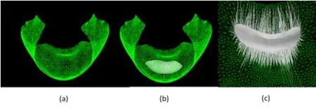
Fig.4 (a)The intermediate mesh.(b)Bone mesh and intermediate mesh.(c)Relationships between corresponding points of the bone mesh and intermediate mesh.

where i donates the index of a vertex(1 6 i 6 N). We use the force vector F to represent the stress vector produced by the movement of the bone,which is a constant value for all points of the bone mesh. Fidenotes the force vector at the corresponding ith point Piin the face mesh structure;θidenotes the angle between the normal at Piand the direction of F.
4.3.2Boundary conditions
In the bone-mapping method,three types of points can be distinguished in the intermediate mesh: forced points,fixed points,and free points:
•Forced points:all points that join at a part of the skull.
•Fixed points:boundary points of the intermediate mesh are kept fixed.
•Free points:all other soft tissue points are free.
During simulation their movement is completely determined by the elastic force at these points.
The boundary points restrict the deformation region and guarantee the stability of the model.
4.3.3Simulation principle
Before analyzing the finite element model based on the tetrahedral mesh,material property values which represent attributes of particular tissue types have to be assigned;these are Young’s modulus and Poisson’s ratio.Measuring precise human tissue material parameters is a difficult task,and many researchers are still working on this topic[9].Here,we assumed the tissue to be isotropic,homogeneous,and linearly elastic.Based on research by Shlivko et al.[10],we set the value of Young’s modulus to 1MPa and the value of Poisson’s ratio to 0.46 during all simulations.
The generated tetrahedral mesh and boundary conditionsserveasinputsforoursofttissuesimulator.When moving the lower jaw,the forced points are assigned according to the bone-mapping method and the force vectors at these points are calculated based on the force-transfer principle. The simulator calculates the displacements of these points in the tetrahedral mesh at each time step. At the same time,the steady-state situation of the free points near the forced points is broken.At each time step,the coordinate states of all points in the intermediate mesh are transferred back to the skin surface mesh and shown in real time.
4.4Control and display
Based on the model-view-controller pattern,our software framework is composed of several modules: the data model module,the view module,the simulation controller module,and the tetrahedron generation module.The data model module manages thepipelineofdataandinteractionbetween interfaces.The simulation controller applies physical rules to elements to modify their positions,velocities,accelerations,and other physical attributes.The tetrahedrongenerationmoduleestablishesthe volume mesh composed of tetrahedral elements.The view module of our framework uses OpenGL to render meshes with appropriate structure,point coordinates,textures,and lighting information.
5 Results and discussion
We have tested the feasibility of the tetrahedral mesh.Wealsomeasuredtheaccuracyofour simulation in terms of the differences between the effects of deformation,and data after operations.
5.1Validation of ST Generator algorithm
ToverifytheoperationoftheSTGenerator algorithm,we extracted the skin from CT image sequences using the marching cubes algorithm[11]and generated a tetrahedral mesh using TetGen[12]. Tocomparethequalityofthetwokindsof tetrahedral mesh,we used the aspect ratio,face angle,and dihedral angle of the data as evaluation criteria.As shown in Fig.5,the tetrahedral meshes have similar peak values for aspect ratio,face angle,and dihedral angle.It indicates that they have the similar structural attributes and the mesh produced by the surface-based tetrahedral generator is suitable for building the tetrahedral volumetric FEM model.
5.2Prediction of deformation
Proplanner is a commercial software product for operation design.It implements prediction of soft tissue deformation based on statistical strategies.In our experiment,we used our prediction system and this commercial system in turn to predict the shape of surface tissue when the mandible is moved to a fixed position.The difference between the results of these two systems is shown in Fig.6.
In addition,we employed the color map method to represent the distance change between the two prediction results.As shown in Fig.7(a),each color represents a difference value in millimetres as indicated by the color scale;hot colors such as red,orange,and yellow denote bulges in our simulation results,while cool colors such as indigo,blue,and violet denote concave parts relative to the simulation results of Proplanner.

Fig.5 Statistics show the differences in aspect ratio,face angle,and dihedral angle of the tetrahedral meshes generated by TetGen and our ST Generator algorithm.
In another experiment,a set data was collected from a patient undergoing jawbone plastic surgery. Figure 8 shows the shape of the face before and after osteotomy and advancement of the mandible. The surgical procedure greatly affected the facialappearance.Part of the mandible was moved into a position where the upper and lower teeth can clench normally.A further small part of the mandible moved to provide a good appearance.We imitated the surgical procedure after capturing these parts of the mandible and measuring the displacement of these parts when moved into position after osteotomy as shown in Fig.9.Figure 7(b)uses a color-map to indicate the distances between corresponding points of the predicted and actual postoperative facial skin surface.Keeping in mind the stability and predictability of maxillofacial surgery,these values show an acceptable accuracy.See Table 1:the first three columns show the number of vertices,faces,and elements used in the facial soft tissue model.The time needed to calculate the new facial appearance and to generate the tetrahedral mesh are summarized in the next two columns.In the last two columns,the mean and variance of errors are shown after simulation.The experiments ran on a standard personal computer with an Intel Core i7 CPU at 2.50GHz and 4GB memory.
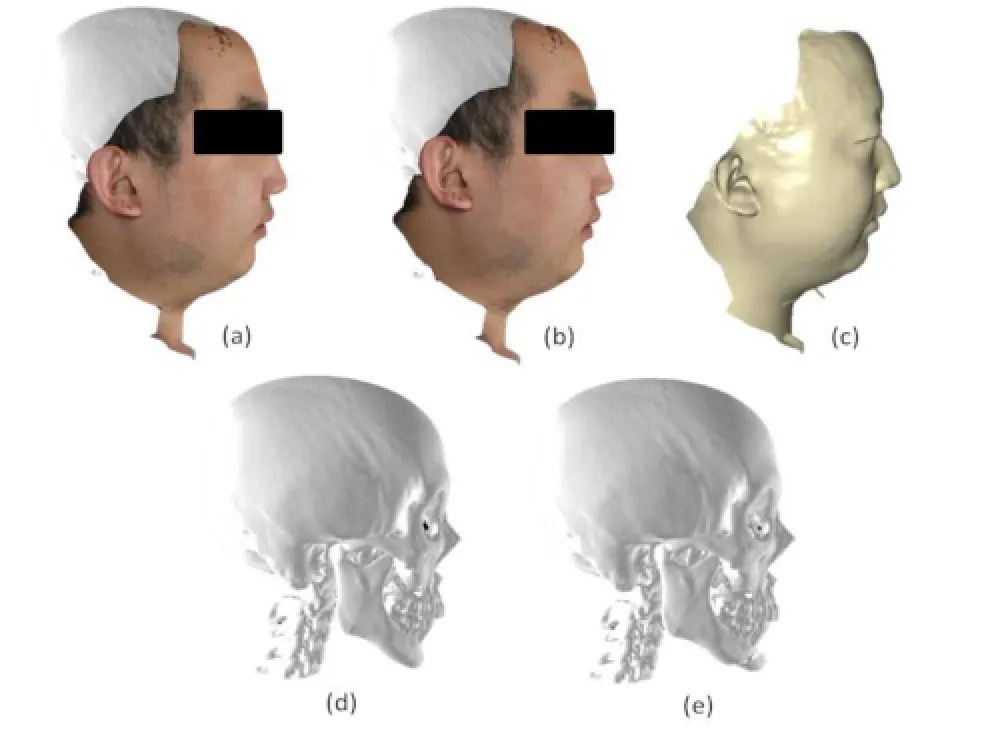
Fig.6 (a)Initial skin surface.(b)Deformed skin surface predicted by our system.(c)Deformed skin surface predicted by Proplanner. (d)Initial bone mesh.(e)Bone mesh with the mandible moved to a fixed position.
Fig.7 Error measurements of the simulated results.
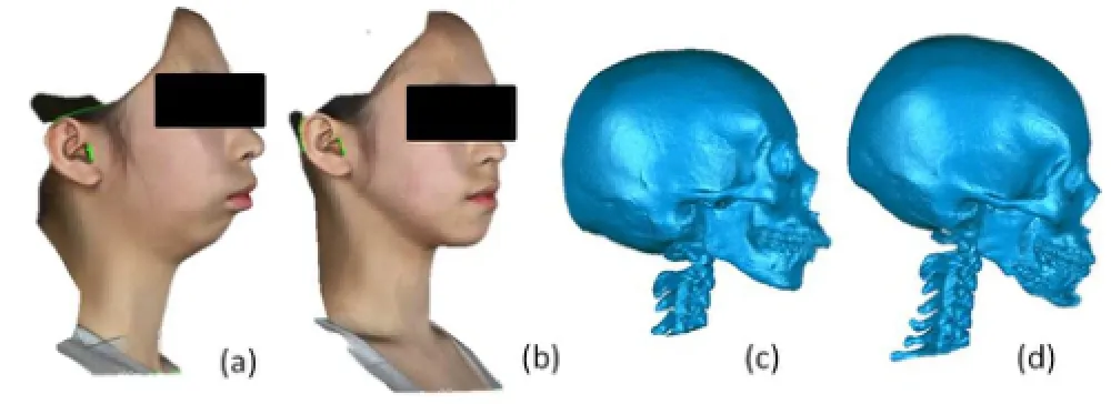
Fig.8 (a)3D scan before surgery.(b)3D scan after surgery.(c)Bone reconstruction model before surgery.(d)Bone reconstruction model after surgery.

Fig.9 Deformation result for the second experiment.
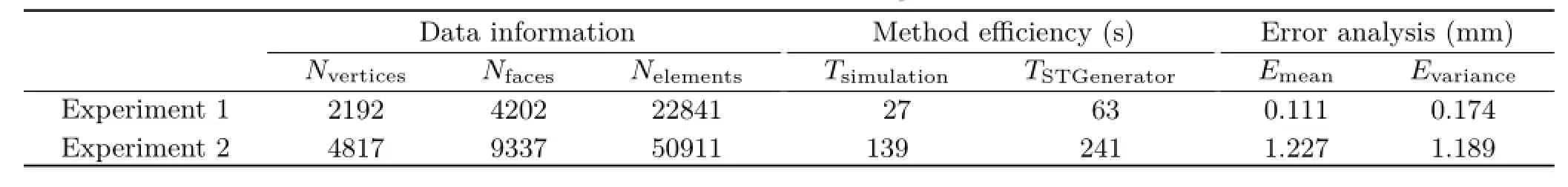
Table 1 Statistics for two experiments
5.3Discussion
The test results of these experiments demonstrated that our system can provide a good prediction of the post-operative facial appearance with texture. However,the prediction results inevitably have small differences from the post-operative data.Analysis reveals some drawbacks that lead to the inaccuracy of our simulated postoperative facial appearance:
•Due to the limitations of numerical calculations,our data model is based on skin surfaces and the mandible.The remaining materials such as fat tissue and muscular tissue are omitted as their presence would produce too great a density of elements.Better results would be obtained if these materials were incorporated.
•The model parameters such as Young’s modulusand Poisson’s ratio are recommended values;measuringprecisehumantissuematerial parameters is a difficult task.
•Some materials are inevitably needed to reconnect partially cut bone or to fix bone cuts in actual surgery,but these are not modelled in the simulated surgery.
6 Conclusions
The results of the first experiment show that our system can achieve similar effects to a commercial system called Proplanner.In addition,our system isabletoshowanappearancewithtexture and avoid an obvious fault at the edge of the deformation area.In the second experiment,we succeeded in imitating a surgical procedure with a complete set of actual patient data.In these experiments we achieved satisfactory results of CMF surgery simulation.The test results demonstrate that fast and good prediction of post-operative facial appearance with texture is feasible.Our surgical simulation system is applicable to computer-assisted CMF surgery.
In future,we plan to implement GPU support into the simulation system to improve performance. We will also consider how to include further soft tissue information such as muscle anatomy and fat tissue in our data models.
Acknowledgements
The authors would like to thank the anonymous reviewers for their comments,which helped to improvethequalityofthispaper.Thiswork described in this paper was supported by a grant fromtheNationalNaturalScienceFoundation of China(Nos.61402305,61375065,61432014,and 61432012),a grant from the National HightechR&DProgramofChina(863Program)(No.2013AA013803),andagrantfromthe Department of Science and Technology of Sichuan Province(No.2014JY0116).
References
[1]Chiang,P.;Zheng,J.;Yu,Y.;Mak,K.H.;Chui,C.K.;Cai,Y.A VR simulator for intracardiac intervention. IEEE Computer Graphics and Applications Vol.33,No.1,44-57,2013.
[2]Vannier,M.W.;Gado,M.H.;Marsh,J.L. Three-dimensional display of intracranial soft-tissue structures.American Journal of Neuroradiology Vol. 4,No.3,520-521,1983.
[3]Pieper,S.D.CAPS:Computer-aided plastic surgery. Ph.D.Thesis.Massachusetts Institute of Technology,Cambridge,MA,USA,1992.
[4]Keeve,E.;Girod,S.;Kikinis,R.;Girod,B.Deformable modeling of facial tissue for craniofacial surgery simulation.Computer Aided Surgery Vol.3,No.5,228-238,1998.
[5]Koch,R.M.;Gross,M.H.;Carls,F.R.;von B¨uren,D.F.;Fankhauser,G.;Parish,Y.I.Simulating facial surgery using finite element models.In:Proceedings of the 23rd Annual Conference on Computer Graphics and Interactive Techniques,421-428,1996.
[6]Maciel,A.; Sankaranarayanan, G.; Halic, T.;Arikatla,V.S.;Lu,Z.;De,S.Surgical model-viewcontroller simulation software framework for local and collaborative applications.International Journal of Computer Assisted Radiology and Surgery Vol.6,No. 4,457-471,2011.
[7]Freutel,M.;Schmidt,H.;D¨urselen,L.;Ignatius,A.;Galbusera,F.Finite element modeling of soft tissues: Material models,tissue interaction and challenges. Clinical Biomechanics Vol.29,No.4,363-372,2014.
[8]Guo,L.;Hu,M.;Li,Y.;Yan,W.;Zhao,L. Three dimension reconstruction of medical images based on an improved marching cubes algorithm. In:Proceedings of the 6th International Conference on Biomedical Engineering and Informatics,64-68,2013.
[9]Ahmadian,M.T.;Nikooyan,A.A.Modeling and prediction of soft tissue directional stiffness using invitro force-displacement data.International Journal of Scientific Research Vol.16,385-389,2006.
[10]Shlivko,I.L.;Petrova,G.A.;Zor’kina,M.V.;Tchekalkina,O.E.;Firsova,M.S.;Ellinsky,D.O.;Agrba,P.D.;Kamensky,V.A.;Donchenko,E.V. Complex assessment of age-specific morphofunctional features of skin of different anatomic localizations.Skin Research and Technology Vol.19,No.1,e85-e92,2013. [11]Newman,T.S.;Yi,H.A survey of the marching cubes algorithm.Computers&Graphics Vol.30,No.5,854-879,2006.
[12]Si,H.TetGen,a delaunay-based quality tetrahedral mesh generator.ACM Transactions on Mathematical Software Vol.41,No.2,Article No.11,2015.
XiaodongTangreceivedhisB.S. degreeinmathematicsandapplied mathematics from Qingdao University. Heisamastercandidateinthe DepartmentofComputerScience,Sichuan University,Chengdu,China. His research interests include soft tissue deformation and machine learning.

JixiangGuoreceivedherPh.D. degree from the Chinese University of Hong Kong’s Department of Computer ScienceandEngineering.Sheisa lecturer in Sichuan University’s College ofComputerScience.Herresearch interests include virtual reality,soft tissue deformation,computer-assisted surgery simulation,and medical image processing.
Peng Li received his doctoral degree in oral and maxillofacial surgery from West China College of Stomatology,SichuanUniversity, andcompleted hispostdoctoralresearchinthe College of Computer Science,Sichuan University.His research interests include maxillofacial reconstruction,computer aided surgery,and biomechanics. Chengdu,China.Prior to that,he was a research fellow in the Department of Electrical and Computer Engineering,National University of Singapore.He is the coauthor of the book Subspace Learning of Neural Networks.His research interests include neural networks and machine learning.
Open AccessThe articles published in this journal aredistributedunderthetermsoftheCreative Commons Attribution 4.0 International License(http:// creativecommons.org/licenses/by/4.0/), whichpermits unrestricted use,distribution,and reproduction in any medium,provided you give appropriate credit to the original author(s)and the source,provide a link to the Creative Commons license,and indicate if changes were made.
Other papers from this open access journal are available free of charge from http://www.springer.com/journal/41095. To submit a manuscript,please go to https://www. editorialmanager.com/cvmj.
JianchengLvreceivedhisPh.D. degreeincomputerscienceand engineeringfromtheUniversityof Electronic Science and Technology of China,Chengdu,China,in 2006.He is currently a professor in the Machine IntelligenceLaboratory, Collegeof Computer Science,Sichuan University,
杂志排行

Computational Visual Media的其它文章
- Fitting quadrics with a Bayesian prior
- Efficient and robust strain limiting and treatment of simultaneous collisions with semidefinite programming
- 3D modeling and motion parallax for improved videoconferencing
- Rethinking random Hough Forests for video database indexing and pattern search
- Learning multi-kernel multi-view canonical correlations for image recognition
- Accurate disparity estimation in light field using ground control points