Computer Simulation of Thin Film Wrinkling on Elastic Substrate
2016-07-05QianruLvHuapingLiConghuaLuXuehaoHeaDepartmentofChemistrySchoolofScienceTianjinUniversityandCollaborativeInnovationCenterofChemicalScienceandEngineeringTianjinTianjin300072ChinaSchoolofMaterialsScienceandEngineeringTi
Qian-ru Lv,Hua-ping Li∗,Cong-hua Lu,Xue-hao Hea. Department of Chemistry,School of Science,Tianjin University,and Collaborative Innovation Center of Chemical Science and Engineering(Tianjin),Tianjin 300072,China b. School of Materials Science and Engineering,Tianjin University,Tianjin 300072,China c. Department of Polymer Science and Engineering,School of Chemical Engineering and Technology,Tianjin University,Tianjin 300072,China
Computer Simulation of Thin Film Wrinkling on Elastic Substrate
Qian-ru Lva,c,Hua-ping Lia,c∗,Cong-hua Lub∗,Xue-hao Hea∗
a. Department of Chemistry,School of Science,Tianjin University,and Collaborative Innovation Center of Chemical Science and Engineering(Tianjin),Tianjin 300072,China b. School of Materials Science and Engineering,Tianjin University,Tianjin 300072,China c. Department of Polymer Science and Engineering,School of Chemical Engineering and Technology,Tianjin University,Tianjin 300072,China
(Dated:Received on December 17,2015;Accepted on March 12,2016)
Numerous theoretical and experimental efforts have been made to explain the dependence of the static wrinkling morphology on the materials' physical properties,whereas the dynamic wrinkling process remains elusive. In the present work,we design a wrinkling model consisting of a soft substrate and a graphene-like rigid thin film to investigate this dynamic process. The simulation shows that the whole wrinkling process includes three stages. At the incubation and wrinkling stages,the stress along the horizon direction of the soft substrate transfers to the stiff film. However,at the equilibrium stage,the stress of the rigid film slowly transfers back to the substrate although the total energy still decreases. It is found that the stress of the substrate concentrates at the top surface,especially at the trough,whereas the stress distribution of the film depends on direction. In the perpendicular direction,the stress at the wave's equilibrium position surpasses that at the crest and trough and,oppositely,the stress concentrates at the crest and trough in the horizon direction. Present model reproduces both wrinkling and delamination patterns and can be a powerful tool to deeply understand the structure deformation of material induced by stress release.
Key words:Wrinkle,Delamination,Stress distribution,Particle model
∗Authors to whom correspondence should be addressed. E-mail:lihuaping@tju.edu.cn,chlu@tju.edu.cn,xhhe@tju.edu.cn
I. INTRODUCTION
Wrinkling or buckling phenomenon widely exists in nature and has potentialities in fabrication and measuring material properties in many fields such as stretchable electronics[1-5],metrology[6-8],micro and nanofabrication[9-13],optical sensors[14,15],microfluidic channel[16,17]. Till now,various methods have been employed in experiments to generate wrinkles such as thermal expansion or contraction[18-20],solvent swelling or shrinkage[21-25]and mechanical stretching or compression[5,26,27]. In general,wrinkling is caused by the stress driven instability,similar to Euler buckling of an elastic column under compression. A typical wrinkling system includes two parts,i.e.,a rigid film and a stretched soft substrate,which are bound together. Wrinkle patterns sensitively depend on the specific properties of the rigid film,the soft substrate and the boundary shapes where the strained substrate restores[6,28-32]. The effects of curved surfaces such as cylindrical,spheroidal and combined substrate on the wrinkling pattern formation have also been studied[9,33-35].
Obviously,deep understanding of the wrinkling mechanism is critical and helpful to precisely tune the structure size and shape for various applications. Numerical simulations based on perturbation analysis,stability analysis and finite element analysis have provided much information on the wrinkling process[18,29,30,36-44]. Im et al. used the Kelvin model to study the evolution of one-dimensional wrinkle pattern. In their study three stages were identified for the wrinkle formation,i.e.,the fastest initial growth,the intermediate growth with mode transition,and an equilibrium wrinkle state[45,46]. Despite these findings,however,the research to the dynamic process is still insufficient,especially at the micro- or nano- meter scale,due to the difficulty in characterizing internal microstructures from experiments and theories.
The wrinkling phenomenon originates from the complex particle interaction between molecules at the micro- or nano- meter scale during restoring. We explore this typical multiscale system with a wrinkling model to provide more detailed information about how the restoring force between molecules induces the formation of wrinkle patterns,how the particles rearrange during the process,and how the material properties and the binding strength determine the delamination phenomenon[47],which are beyond the scope of the past methods and technologies. In the present work,a new and simple model based on particles was devel-oped. The dependence of wrinkling on the film modulus,the substrate thickness,the prestretch,and the binding strength was systematically investigated. The simulation results are compared with previous theories and experiments and more dynamic information about the force and energy evolution during the wrinkling process is provided.

TABLE I Force field parameters(in reduced units).
II. MODEL AND METHODS
A. Wrinkling model
In the present model,the wrinkling system includes two parts:a single-layer stiff film and a thick elastomeric substrate(Fig.1(a)),corresponding to the rigid film and the polymer substrate in experiment[5],respectively. The film is represented with a graphenelike layer consisting of hexagon distributed particles. The elastic substrate is represented using a cross-linked structure as shown in Fig.1(a). To make the model simple,both particles in the film and the substrate are connected by harmonic bonds and angles with potentials as follows:

here b0and θ0are the equilibrium bond length and angle,respectively,and b and θ indicate the corresponding instantaneous values. The coefficients Kband Ka(see the supplementary materials for the calculation)are listed in Table I. For particles further than three continuous bonds,the nonbonded interaction is considered using the Lennard-Jones(LJ)potential:
For r<2.23 rmin,

For r≥2.23 rmin,VLJ(r)=0.
The LJ interaction is truncated at the cut-off radius rc=2.23rmin. To mimic the adhesive interaction between the film and the substrate,more intensive LJ potential is also applied between the particles from the two components by multiplying the well-depth with a factor m,which is shown to be an influencing factor for the wrinkling morphology in the discussion section. The complete parameters for the bonded and nonbonded potentials of the system are listed in Table I. For convenience,we use reduced units for all the quantities in the present work.
The moduli of the stiff film and the elastomeric substrate can be tuned by varying the coefficients Kband Ka. We fix the Kb/Karatio to be 500 for convenience. It is shown that the modulus of the film increases linearly as the coefficients increase(see Fig.S1 and S2 in supplementary materials). The modulus of the substrate Esis set as a constant(889.9)in the current parameter settings.

FIG. 1 (a)Schematic illustration of the wrinkling model and(b)the simulation process. F and S represent the film and the substrate,respectively. H is the substrate thickness. The substrate underwent uniaxial stretching,filmbinding and strain-releasing,successively. fpreindicates the prestretch ratio of the substrate.
B. Simulation scheme
The molecular dynamics simulation was carried out in three steps for the wrinkling(Fig.1(b)):(i)The elastomeric substrate was stretched along the z direction with prestretch ratio fpreat a constant temperature 2.49. The stretching of the substrate was realized by the deformation algorithm,i.e.,the box length in the zdirection increases at a constant velocity of 0.01,until the stretched length is fpretimes the initial substrate length.(ii)The stretched elastomeric substrate and the rigid film were put together to bind under the NV T ensemble for the time of 103. It is assured that the film and substrate are bound tightly.(iii)The composite system relaxed under the NPT ensemble for the time of 104and the wrinkle pattern occurs during the substrate restoring. The stochastic dynamics was used to integrate the equations of motion with a time step of 0.001 and 0.0005 for systems with softer and stiffer film,respectively. The Berendsen algorithm was used for the pressure coupling in the NPT simulation and the pressure is set as 0.06. Periodic boundary conditions were used in the simulation and thick spaces were set above and below the substrate to avoid unexpected interactions. All simulations were carried out with GROMACS 4.6[48]. The influences of the stiffness of the film(Ef),the substrate thickness(H),and the binding strength (m)and fpreon the wrinkling phenomenon were investigated.
C. Fourier transform method
Fast Fourier transform[49]is used to analyze the characteristic parameters of the wrinkle pattern,i.e.,the wavelength λ and the amplitude Af. Because the substrate was stretched uniaxially,it is reasonable to average the single-layer film surface to a wave curve along the stretching direction,which facilitates the following calculation. Then,the cubic spline interpolation method is used to obtain the equally spaced data suited for the Fourier transform method. After these treatments,the Fourier transform method is used as follows:

here,n is the point index of the total N points along the wave,x(n)is the value at the nth point and k indicates the frequency index. The complex moduli of X are calculated and the left and right halves of |X| are swapped to obtain the frequency spectrum F(k)(only the right half is presented in Fig.S3(supplementary materials)because the whole spectrum is symmetric). The characteristic amplitude Afcan be calculated through 2Fmax/N,where Fmaxindicates the maximum of F(k). The characteristic wavelength λ can be calculated through N∆x/nmax,where nmaxindicates the point index of the maximum on the frequency spectrum. ∆x is the interval between neighbor points in the wave curve so that N∆x means the box length along the wrinkling direction.
D. Stress calculation
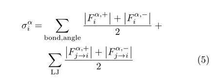
The stress σ of a particle in the system in a certain direction is defined as the average of the absolute force values imposed by all other particles through bonds,angles and nonbonded interactions along the direction:

with α=x,y,z,where α denotes the direction,the plus and minus signs denote the components of the force along the positive and negative directions,respectively.
III. RESULTS AND DISCUSSION
The wrinkling process is a typical shrinking process in which the size of the compound system decreases along the prestretch direction of the substrate and the shrinkage stress of the system is released. Figure 2(a)shows the size evolution of the compound system during wrinkling process. Here,the system size is represented by the relative length,i.e.,the ratio of lx/l0,where lxis the instantaneous substrate length along the z direction and l0is the corresponding initial value before stretching the substrate. It is found that the wrinkling process shows three stages. At the incubation stage,it is shown that the substrate has been restored markedly while both the stiffer film and softer film keep flat(see the configurations at the time of 10 in Fig.2(b)). Nevertheless,the particles in the film are distorted due to the compression. These defects become the seeds of the following pattern formation. After an incubation time(t<10),the wrinkling happens quickly(10<t<50). With the continuous restoring of the substrate,wrinkles emerge on the film and the top layer of the substrate(Fig.2(b)). After the fast wrinkling stage,the wave-structure optimization slowly continues till final equilibrium.
As the film modulus Efdecreases,the film becomes softer and the incubation time of wrinkling process decreases. The initial shrinking speed also increases with Efdecreasing because the substrate hold by the soft film is easier to restore. At the time of about 50,the drop of the relative length slows down,indicating that a metastable stress balance is formed between the stretched substrate and the compressed film in the system. Afterwards,stiffer film holds the balance and the transformations of the film and substrate take place under this balance,resulting in the wrinkle pattern while softer film forms delamination pattern. It should be noted that the disordered wrinkle pattern is an intermediate state during the delamination process(see Fig.2(b)),which is also observed by Wang and Zhao[50].

FIG. 2 (a)The relative length lx/l0as a function of time under varied film moduli and(b)the typical formation processes of the wrinkle and delamination patterns. The time t indicated in(b)was associated with the right configurations during the process. Other parameters are set as follows:the prestretch ratio fpreis 13.0%,the substrate thickness H is 12 and the binding strength factor m is 30. All quantities are in reduced units.
In order to deeply understand the wrinkling mechanism in terms of stress release,the evolutions of the potential energy U and stress σ of the system during wrinkling are analysed in Fig.3 for a typical wrinkling system(Ef=4.24×10⁶,fpre=13.0%,H=12 and m is 30). The stresses of the substrate and the film are averaged over all the particles of each component for the z and y directions,respectively. At the incubation stage,the potential energy and stresses change weakly. At the wrinkling stage,it is shown that the potential energy U of the total system(including the bond,angle,and LJ interactions within each component and the adhesive interaction between them)drops obviously due to the stress release of the substrate. As the substrate restores,the z-direction stress of the substrate decreases quickly and serves as the major source of power for the wrinkling. The shrinkage stress is transferred from the soft substrate to the stiff film. Because the transformation is so fast,the particles on the stretched substrate cannot move back to the equilibrium position,especially under the influence of the above adhered film. As a result,many defects appear in the cubic structure of the substrate and result in the increase of the stress at the y direction. The accumulation of the stress of the film also completes at this stage and both the yand z-direction stresses increase quickly. But,at the late stage of wrinkling where the wave-structure is optimized,the stress of the rigid film in the horizon direction(z)is slowly transferred back to the substrate. The z-direction stresses of the substrate and film slightly increase and decrease,respectively(Fig.3(b)and(d)). This stress transfer is due to the inclination of the interaction plane between the film and the substrate,preparing for the wrinkle formation. After the stress accumulation stage,the system enters a dynamic balance where small wrinkles form and merge randomly.

FIG. 3 The evolutions of the potential energy U of the system(a),the average stress σ on the substrate particles(b,c)and the film particles(d,e)in different directions. The red curves indicate the average value of the scatters based over a window of data points. The parameters are set as follows:Ef=4.24×10⁶,fpre=13.0%,H=12,m=30.
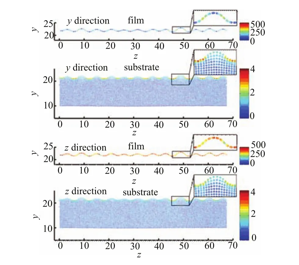
Figure 4 shows the final stress distribution on the zy plane(side view)of the wrinkling system corresponding to Fig.3. The stress for each particle in the film and substrate along the perpendicular and horizon directions in the wrinkling system are calculated,respectively. Thecoordination and the stress data of the particles along the x direction are averaged. Because the stress in the film is two orders larger than that in the substrate,it is clearer to draw their stress distribution separately than to put them together. The enlarged figures clearly show the coordination and stress distributions in the wave. For the film,the stress at the horizon direction is obviously larger than the perpendicular direction(the former is approximately three times as large as the latter as shown in Fig.3(d)and(e)),indicating that the film is mainly compressed along the substrate's restoring direction. The distribution of the stress also significantly depends on the direction. At the y direction,the stress at the equilibrium position is larger than the trough and crest. In contrast,at the z direction,the stress at the equilibrium position is relatively smaller. Differentiated from the film,the stress on the substrate is more likely to focus at the trough because the particles at the trough are severely squashed by the trough of the film wave. Oppositely,the particles at the crest swell gradually from the bulk to the top layer of the substrate. The stress distribution shows that the transferring of the stress of the stiff film back to the substrate in the horizon direction is due to the wave structure of the rigid thin film which stretches/compresses the upper particle layers of the soft substrate.

FIG. 4 The stress on the film particles and the substrate particles at the y and z directions. The x and y coordinates indicate the coordination of particles in z and y directions,respectively. A wave is specially enlarged in the box. The color bar is in reduced units. The parameter settings are the same as Fig.3.
During the wrinkling process,the characteristic parameters of the wrinkle pattern,i.e.,the wavelength λ and the amplitude Af,are monitored using the Fourier transform method(Fig.S4 and Fig.S5 in supplementary materials). It is shown that the amplitude and the wavelength both increase quickly at the first stage and many small waves form and join together. Because the amplitude and the wavelength almost get stable after 5×10³,we average the wavelength between 5×10³and 104and plot it as a function of the film modulus Ef(Fig.S6 in supplementary materials). It has been reported by many theoretical reports that the wavelength of the wrinkle pattern scales with the film modulus with an exponential index 1/3[30,36-41]. The simulation presented here qualitatively complies with the theoretical prediction.

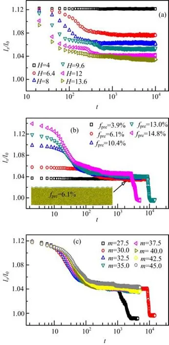
FIG. 5 The relative length lx/l0as a function of time under the impact of(a)substrate thickness H,(b)prestretch ratio fpre,and(c)binding strength factor m. Representative configuration is given for the system with fpreequal to 6.1% in(b). Other parameters for each panel are set as follows:(a)Ef=1.01×10⁶,fpre=13.0%,m=35.(b)Ef=6.72×10⁵,H=12,m=30.(c)Ef=6.72×10⁵,H=12,fpre=13.0%.
Besides the film modulus,the dependence of the wrinkling phenomenon on H,the fpre,and m is investigated. It is clearly shown in Fig.5(a)that thin substrate fails to restore because the stored energy is relatively small to deform the rigid film. As the thickness increases,the shrinking speed of the first stage increases dramatically and the equilibrium substrate length gets closer to the initial value because the substrate gets strong enough to dominate the stress balance. For system with small prestretch ratio,the substrate is powerless to restore. When fpreincreases to 6.1%,some wrinkles appear and coexist with the flat domain,as the representative configuration in Fig.5(b)shows. More wrinkles emerge as fprefurther increases. However,too large prestretch ratio is apt to make the film delaminate. Figure 5(c)shows the influence of the binding strength on the wrinkling process. When the factor m is small,the binding between the substrate and the film is weak and the film is easy to hump to delaminate from the substrate. In summary,four conditions are critical for the success wrinkling:enough stiffness of the film,thick substrate,modest prestretch ratio at the initial stretching stage,stable binding between the film and the substrate. At the limitation of wrinkling conditions,the delamination will happen. The results are consistent with previous experimental work on the dependence of the wrinkling phenomena on the film modulus and the binding strength[50]. Our model can reproduce not only the wrinkling process but also the delamination process. These findings significantly improve the understanding of the formation process of the wrinkle pattern.
IV. CONCLUSION
In this work,we develop a novel model and simulate the wrinkling process of the film-substrate compound system. The simulation shows that the whole wrinkling process includes three stages,i.e.,incubation,wrinkling,and structure optimization. At the first two stages,the stress along the horizon direction is transferred from the soft substrate to the stiff film. But,at the last stage where the structure is optimized,the stress of the rigid film in the horizon direction is slowly transferred back to the substrate. During the whole process the total energy continues decreasing. The stress of the substrate is found to concentrate at the top surface,especially at the trough. In contrast,the stress distribution of the film depends on the direction. In the perpendicular direction,the stress at the equilibrium position of the wave is larger than that at the crest and trough. Oppositely,the stress concentrates at the crest and trough of the wave in the horizon direction. Influences of the film stiffness,substrate thickness,prestretch ratio of the soft substrate and binding strength are also examined. The wavelength increases as the film gets stiffer,which qualitatively agrees with the theoretical prediction. Our simulation is helpful to deeply understand the wrinkling mechanism for the design of pattern structure using material deformation induced by stress release. Supplementary materials:The dependence of the film and substrate moduli on the force field parameters,the frequency spectrum of the Fourier transform method,the amplitude and wavelength evolutions of the film and the impact of film modulus on the wavelength are shown.
V. ACKNOWLEDGMENTS
This work was supported by the High Performance Computing Center of Tianjin University,China and the National Natural Science Foundation of China (No.91127046,No.21274107,and No.21474075).
[1]J. A. Rogers,T. Someya,and Y. Huang,Science 327,1603(2010).
[2]S. P. Lacour,S. Wagner,Z. Huang,and Z. Suo,Appl. Phys. Lett. 82,2404(2003).
[3]D. Y. Khang,H. Jiang,Y. Huang,and J. A. Rogers,Science 311,208(2006).
[4]D. Y. Khang,J. A. Rogers,and H. H. Lee,Adv. Funct. Mater. 19,1526(2009).
[5]Y. Sun,V. Kumar,I. Adesida,and J. A. Rogers,Adv. Mater. 18,2857(2006).
[6]C. M. Stafford,C. Harrison,K. L. Beers,A. Karim,E. J. Amis,M. R. VanLandingham,H. C. Kim,W. Volksen,R. D. Miller,and E. E. Simonyi,Nat. Mater. 3,545(2004).
[7]E. A. Wilder,S. Guo,S. Lin-Gibson,M. J. Fasolka,and C. M. Stafford,Macromolecules 39,4138(2006).
[8]C. M. Stafford,B. D. Vogt,C. Harrison,D. Julthongpiput,and R. Huang,Macromolecules 39,5095(2006).
[9]B. Li,Y. P. Cao,X. Q. Feng,and H. Gao,Soft Matter 8,5728(2012).
[10]P. J. Yoo and H. H. Lee,Langmuir 24,6897(2008).
[11]A. Schweikart and A. Fery,Microchim. Acta 165,249 (2009).
[12]A. Schweikart,A. Fortini,A. Wittemann,M. Schmidt,and A. Fery,Soft Matter 6,5860(2010).
[13]J. Yin and C. Lu,Soft Matter 8,6528(2012).
[14]C. Harrison,C. M. Stafford,W. Zhang,and A. Karim,Appl. Phys. Lett. 85,4016(2004).
[15]Y. Mei,S. Kiravittaya,M. Benyoucef,D. J. Thurmer,T. Zander,C. Deneke,F. Cavallo,A. Rastelli,and O. G. Schmidt,Nano Lett. 7,1676(2007).
[16]Y. Mei,S. Kiravittaya,S. Harazim,and O. G. Schmidt,Mater. Sci. Eng.,R 70,209(2010).
[17]C. Lu,H. M¨ohwald,and A. Fery,Soft Matter 3,1530 (2007).
[18]N. Bowden,S. Brittain,A. G. Evans,J. W. Hutchinson,and G. M. Whitesides,Nature 393,146(1998).
[19]W. T. S. Huck,N. Bowden,P. Onck,T. Pardoen,J. W. Hutchinson,and G. M. Whitesides,Langmuir 16,3497 (2000).
[20]J. Y. Park,H. Y. Chae,C. H. Chung,S. J. Sim,J. Park,H. H. Lee,and P. J. Yoo,Soft Matter 6,677(2010).
[21]S. J. Kwon,J. H. Park,and J. G. Park,Phys. Rev. E 71,011604(2005).
[22]J. Y. Chung,A. J. Nolte,and C. M. Stafford,Adv. Mater. 21,1358(2009).
[23]M. Guvendiren,S. Yang,and J. A. Burdick,Adv. Funct. Mater. 19,3038(2009).
[24]M. Guvendiren,J. A. Burdick,and S. Yang,Soft Matter 6,2044(2010).
[25]Y. Ni,L. He,and Q. Liu,Phys. Rev. E 84,051604 (2011).
[26]Y. Sun,W. M. Choi,H. Jiang,Y. Y. Huang,and J. A. Rogers,Nat. Nanotechnol. 1,201(2006).
[27]H. Jiang,Y. Sun,J. A. Rogers,and Y. Huang,Appl. Phys. Lett. 90,133119(2007).
[28]J. Song,H. Jiang,Z. J. Liu,D. Y. Khang,Y. Huang,J. A. Rogers,C. Lu,and C. G. Koh,Int. J. Solids Struct. 45,3107(2008).
[29]P. J. Yoo,K. Y. Suh,S. Y. Park,and H. H. Lee,Adv. Mater. 14,1383(2002).
[30]K. Efimenko,M. Rackaitis,E. Manias,A. Vaziri,L. Mahadevan,and J. Genzer,Nat. Mater. 4,293(2005).
[31]E. P. Chan and A. J. Crosby,Soft Matter 2,324(2006).
[32]C. Jiang,S. Singamaneni,E. Merrick,and V. V. Tsukruk,Nano Lett. 6,2254(2006).
[33]G. Cao,X. Chen,C. Li,A. Ji,and Z. Cao,Phys. Rev. Lett. 100,036102(2008).
[34]J. Yin,Z. Cao,C. Li,I. Sheinman,and X. Chen,Proc. Natl. Acad. Sci. USA 105,19132(2008).
[35]J. Yin,X. Chen,and I. Sheinman,J. Mech. Phys. Solids 57,1470(2009).
[36]E. Cerda and L. Mahadevan,Phys. Rev. Lett. 90, 074302(2003).
[37]X. Chen and J. W. Hutchinson,J. Appl. Mech. 71,597 (2004).
[38]X. Chen and J. W. Hutchinson,Scr. Mater. 50,797 (2004).
[39]R. Huang,J. Mech. Phys. Solids 53,63(2005).
[40]Z. Y. Huang,W. Hong,and Z. Suo,J. Mech. Phys. Solids 53,2101(2005).
[41]H. Jiang,D. Y. Khang,H. Fei,H. Kim,Y. Huang,J. Xiao,and J. A. Rogers,J. Mech. Phys. Solids 56,2585 (2008).
[42]C. T. Koh,Z. J. Liu,D. Y. Khang,J. Song,C. Lu,Y. Huang,J. A. Rogers,and C. G. Koh,Appl. Phys. Lett. 91,133113(2007).
[43]Z. Huang,W. Hong,and Z. Suo,Phys. Rev. E 70,030601(2004).
[44]S. Tang,Y. Li,Y. Yang,and Z. Guo,Soft Matter 11,7911(2015).
[45]S. H. Im and R. Huang,J. Appl. Mech. 72,955(2005).
[46]R. Huang and S. H. Im,Phys. Rev. E 74,026214(2006).
[47]H. Mei,R. Huang,J. Y. Chung,C. M. Stafford,and H. H. Yu,Appl. Phys. Lett. 90,151902(2007).
[48]D. Van Der Spoel,E. Lindahl,B. Hess,G. Groenhof,A. E. Mark,and H. J. C. Berendsen,J. Comput. Chem. 26,1701(2005).
[49]M. Frigo and S. G. Johnson,Proc. IEEE 93,216(2005). [50]Q. Wang and X. Zhao,J. Appl. Mech. 81,051004 (2014).
DOI:10.1063/1674-0068/29/cjcp1512254
杂志排行
CHINESE JOURNAL OF CHEMICAL PHYSICS的其它文章
- Impact of Eu3+Ions on Physical and Optical Properties of Li2O-Na2O-B2O3Glass
- Investigation of Ultrafast Electronic Transfer Process on Organic/Inorganic Heterojunction by Femtosecond Transient Absorption
- Ordered Toroid Structures of Nanoparticles in Self-attractive Semiflexible Polymer/Nanoparticle Composites
- Virtual Screening of Human O-GlcNAc Transferase Inhibitors
- Morphology and Growth Process of Bat-like ZnO Crystals by Thermal Evaporation
- Epitaxial Growth and Thermoelectric Measurement of Bi2Te3/Sb Superlattice Nanowires
