Numerical Analysis on Motion of Multi-column Tension-Leg-Type Floating Wind Turbine Basement
2016-05-12FanXiangZhangJingxinLiuHuaMOEKeyLaboratoryofHydrodynamicsSchoolofNavalArchitectureOceanCivilEngineeringShanghaiJiaoTongUniversityShanghai200240ChinaCollaborativeInnovationCenterforAdvancedShipandDeepSeaExplorationSchool
Fan Xiang,Zhang Jingxin,Liu Hua,2*.MOE Key Laboratory of Hydrodynamics,School of Naval Architecture,Ocean&Civil Engineering,Shanghai Jiao Tong University,Shanghai 200240,P.R.China;2.Collaborative Innovation Center for Advanced Ship and Deep-Sea Exploration,School of Naval Architecture,Ocean&Civil Engineering,Shanghai Jiao Tong University,Shanghai 200240,P.R.China(Received 22 August 205; revised 6 November 205; accepted 5 January 206)
Numerical Analysis on Motion of Multi-column Tension-Leg-Type Floating Wind Turbine Basement
Fan Xiang1,Zhang Jingxin1,Liu Hua1,2*
1.MOE Key Laboratory of Hydrodynamics,School of Naval Architecture,Ocean&Civil Engineering,
Shanghai Jiao Tong University,Shanghai 200240,P.R.China;
2.Collaborative Innovation Center for Advanced Ship and Deep-Sea Exploration,School of Naval Architecture,
Ocean&Civil Engineering,Shanghai Jiao Tong University,Shanghai 200240,P.R.China
(Received 22 August 2015; revised 16 November 2015; accepted 5 January 2016)
Abstract:The offshore wind energy presents a good solution for the green energy demand.The floating offshore wind turbine (FOWT) is one of the most potential choices of the basement construction for offshore wind turbines in deep water.Hydrodynamic performance of multi-column tension-leg-type floating wind turbine is investigated numerically,particularly at its motion responses.Based on the Navier-Stokes equations and the volume of fluid method,a numerical wave tank (NWT) is established to simulate the floating structure system.The analytical relaxation method is adopted to generate regular waves.Dynamic mesh method is used to calculate the motion of the floating body.Hydrostatic decay of motion and hydrodynamic forces in the regular wave are provided.The computation results agree with the experimental data available.Numerical results show that the wave force on the lower pontoon of the system is the greatest while that on the center column is the smallest.Detailed information about the changes of the wave forces on different elements of the floating system is discussed.
Key words:numerical wave tank (NWT) ; wave-floating body interaction; fluid-solid coupling; offshore wind turbine
CLC number: O321Document code: AArticle ID: 1005-1120(2016)01-0073-07
* Corresponding author,E-mail address: hliu@ sjtu.edu.cn.
How to cite this article: Fan Xiang,Zhang Jingxin,Liu Hua.Numerical analysis on motion of multi-column tension-leg-type
floating wind turbine basement[J].Trans.Nanjing Univ.Aero.Astro.,2016,33(1) : 73-79.
http: / /dx.doi.org/10.16356/j.1005-1120.2016.01.073
0 Introduction
Due to the energy crisis and climate-change problem,the wind energy exploitation is a booming industry in the world.Compared with onshore wind energy,there are several advantages of the offshore wind energy,such as the abundant resource,the fast wind speed,the stable operation,the high utilization ratio and the little pollution.These merits greatly promote the development of offshore wind energy[1].The first large-scale offshore wind farm in the world named Homs Res was built in Denmark in 2002.In 2005,the Chinese first large-scale offshore wind farm was constructed in the East China Sea coast nearby Shanghai city.By now,most offshore wind farms have been built in the shallow water region with fixed foundations.For the consideration of higher economic benefits and less influence to the fisheries and shipping,there is a tendency to develop the wind farms into the deep sea water.Correspondingly,the floating offshore wind turbine (FOWT) is becoming one feasible engineering construction.
Several full-scale floating foundations have been installed.In 2009,Statoil installed their Spar Buoy with a 2.3 MW wind turbine and in 2013,a semi-submersible foundation by Mitusi with a 2 MW turbine was commissioned off the Fukushima coast[2].Besides those,many experimental and numerical works have been carried out to investigate some important issues.Antonutti et al.[3]investigated the effects of wind-induced inclination on floating wind turbine dynamics.Cao et al.[4]studied the dynamic loads and wave prediction for large wind turbines.Lee et al.[5]focused on the dynamic response analysis of a float-ing offshore structure subjected to the hydrodynamic pressures induced from seaquakes.Farrugia et al.[6]studied the aerodynamic performance of a model FOWT.The investigations of tension leg platform (TLP) foundations for FOWT are developing fast.Adam et al.[2]did an experimental investigation on the evaluation of internal force superposition on a GICON®-TLP for wind turbines.Ke et al.[7]did numerical work on the dynamic characteristic of floating offshore wind turbine systems.Bae et al.[8]simulated the rotor-floatertether coupled dynamics including second-order sum-frequency wave loads for a mono-column-TLP-type FOWT.
Many methods,mostly based on the potential flow theory and the Morison equations,have been developed for studying floating offshore structures theoretically and numerically in the past several decades[8-9].With the development of the numerical models,the numerical wave tank (NWT) is becoming one practical and efficient tool in the research of hydrodynamics and rigid boy motions.Yan et al.[10]developed a fully nonlinear potential theory based NWT to simulate the interaction between steep waves and 2D floating bodies.U-sing the viscous fluid flow model,NWT has been applied to studying the interaction of waves and structures in coastal and offshore engineering,such as Lu et al.[11]and Guo et al.[12]on steep wave effects and overtopping on a sea dikes,and Westphalen et al.[13]on the focused waves and the wave-structure interactions.
Here,a NWT based on the open-source OpenFOAM,is developed to simulate the dynamic characteristics of WindStar TLP system as shown is Fig.1.Both the hydrostatic decay motion and the dynamic response of WindStar in the regular wave are carried out by means of physical experiments and the numerical simulations.A good agreement between the computed motion responses and and the experimental data shows accuracy and reliability of the numerical model.
1 Numerical Methods
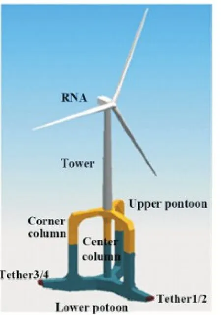
Fig.1 Schematic of WindStar
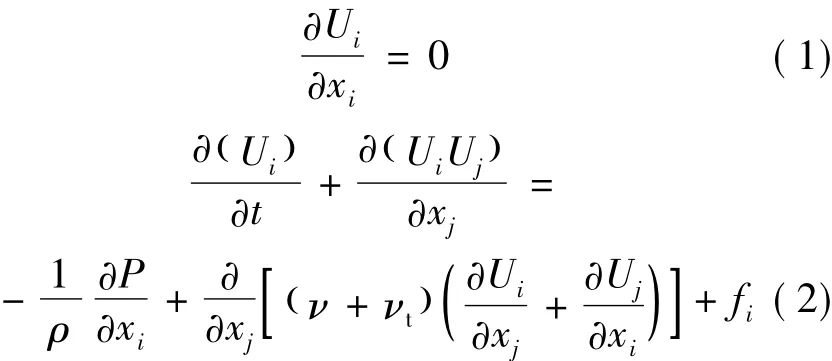
Consider an incompressible,viscous fluid flow.The governing equations include a continuity equation and momentum conservation equations,i.e. where Uiis the velocity,ρ the density of water,ν the fluid viscosity coefficient,νtthe turbulent eddy coefficient,fithe volume force,and P the pressure.
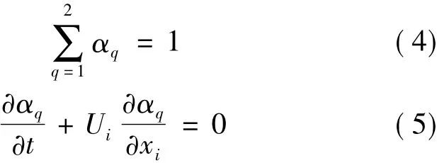
Numerous methods have been applied in multiphase solver to capture the air-water interface,such as Marker and Cell (MAC) method,Level-Set method and Volume of Fluid method.The volume of fluid method is used here.The coefficient αqis defined as the volume fraction coefficient of the fluid q

where αqsatisfies the following equations
The numerical model is based on wave-Foam[14]which is a two-phase flow package developed from the default solver interFoam in OpenFOAM.Thefinite-volumemethod (FVM) and the implicit Eulerian method are applied to the spatial discretization and the time integration of the governing equations.MergedPISO-SIMPLE (PIMPLE) algorithm is used for the solution of pressure-velocity coupling.The semi-implicit method for pressure-linked equations (SIMPLE) algorithm allows the calculation of pressure on a mesh from velocity components by coupling the Navier-Stokes equations with an iterative procedure.The pressure implicit splitting operator (PISO) algorithm has been applied in the SIMPLE algorithm to rectify the pressure-velocity correction[15].The Courant number is used to adjust the advancing time step as the following formula

where Δt is the advancing time step,U the velocity,and Δx the length scale of cells in the U direction.To keep the stability of calculation,the Courant number should not be larger than 1.
The computational domain of NWT can be divided into the wave generating zone,the working zone and the sponge zone.Sketch of the computational domain is shown in Fig.2 with the side viewpoint.
The time series of velocity,pressure and surface elevation are prescribed at the left side of the computational domain using the theoretical solution of regular progressive waves.
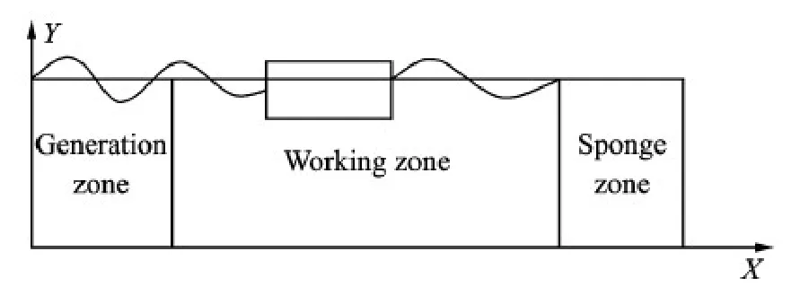
Fig.2 Schematic of NWT
In order to absorb the reflecting waves,a relaxation function written as

is added into the numerical codes in the generating zone and sponge zone.The computed value of each variables is updated using the relaxation algorithm:= Ccomputed+(1-C )target,where is either U or α,and α the volume fraction.The definition of X is such that C is always 1 at the interface between the non-relaxed part of the computational domain and the relax zone as shown in Fig.3.

Fig.3 Function C(X) in different zones
Two coordinate systems are used to describe the motion of the rigid body as shown in Fig.4.The framework OXYZ is the earth-fixed coordinate system and its origin locates at the center of gravity of the WindStar body,in which the Z-axis is upward.Relatively,the local framework O' X'-Y'Z' is the body-fixed coordinate system and its origin locates at the center of gravity of the WindStar body with the Z'-axis along the centerline during the body motion.At the initial moment,the two coordinate systems coincide with each other.
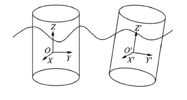
Fig.4 The coordinate systems
The FOWT is considered as a rigid body.The motion can be described by the following well-known non-linear equations.
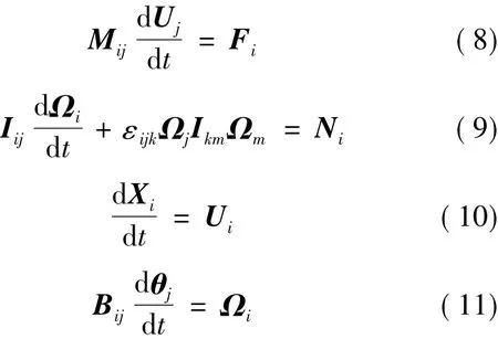
where Mijand Iijare the mass and inertia matrix,Fiand Nithe total external force and the moment of the force about center of gravity,respectively,θithe Euler angles,Ωithe angular velocity,Bijthe matrix formed by Euler angular,and εijkthe permutation tensor.The translational motion equations Eqs.(8 ),(10 ) are written in OXYZ system,while the rotational motion equations Eqs.(9 ),(11 ) are writtenin O' X' Y' Z' system.
2 Model Setting-up
The foundation of offshore wind turbine is composed of a lower pontoon,a upper pontoon,a center column and three corner columns,as shown in Fig 1.The influence of tower and turbine are model by mass and moment of inertia.In the following section,the three corner columns are named as front column,left column and right column which are depicted in Fig.5.The geometric scale of the model is 1∶50.The wave parameters are listed in Table 1.The main geometrical and physical parameters are listed in Table 2.The tethers are considered as linear springs.The length of tension leg is 2.506 m and the rest length is 2.478 m.The coordinates of the anchors of these tethers are listed in Table 3,where the origin is the center of mass.
NWT for investigating the WindStar motion forced by waves is shown in Fig.6.The total length of the computational domain is 6L with 1L long for the wave generating zone and 3L long for the wave absorbing zone.The width of NWT is 1.25L,and the still water depth is about 1.44h.WindStar is located at the center of the working zone in NWT.
按照以职业素质和职业技术应用能力培养为主线的原则,将专业理论的学习和操作技能的训练贯穿整个培养过程,以保证培养目标的有效性;通过对专业人才培养模式的改革和重点专业建设,调整优化专业结构,构建合理的专业体系,力争办成具有国内同类学校引领和示范作用的特色专业。
In the working zone,the regular mesh size in the wave direction is Δx = L/40,and the spanwise
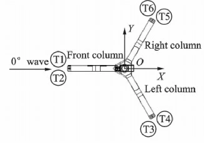
Fig.5 Structure of WindStar

Table 1 Wave parameters m
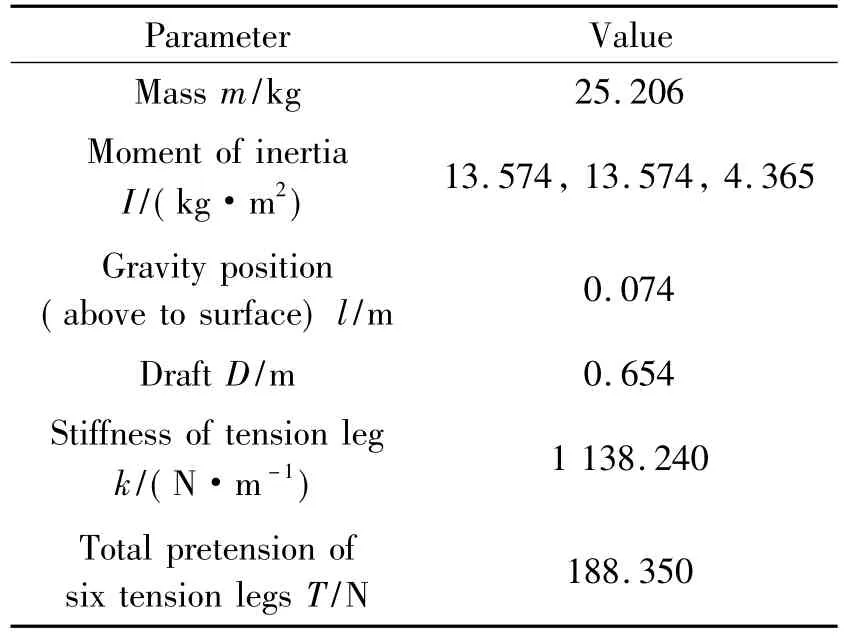
Table 2 Geometrical and physical parameters
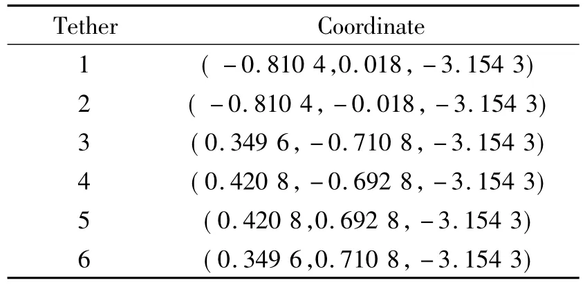
Table 3 Coordinates of six anchors
mesh size is Δy = L/20.In order to accurately capture the free surface,the grid near the free surface is Δz = H/10.The mesh around the WindStar body is gradually refined toward the rigid body.Fig.7 shows the details of the local meshes around the floating body.
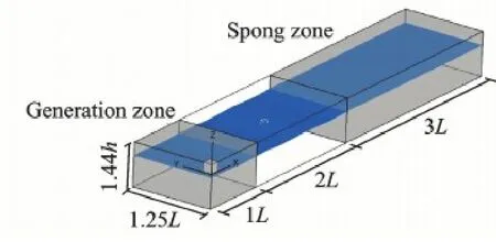
Fig.6 Computational domain of 3D NWT
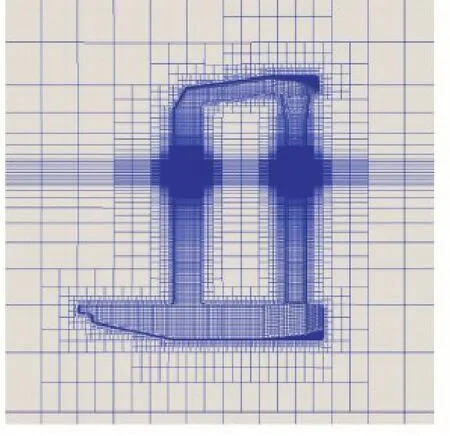
Fig.7 Local meshes around WindStar
3 Results and Discussion
The decay processes of the heaving,surging and pitching motions are simulated,respectively,and compared to the measured values in time domain.WindStar is initially perturbed with a given displacement along each degree of freedom (DOF) and then released to move freely.The results of these three cases are presented in Fig.8 along with experimental results.The attenuation frequencies are listed in Table 4.In heaving and surging motions the computed frequencies match the measured results while the computed frequency overestimates 14%of the measured value in pitching motion.As shown in Fig.1,there is a long tower in WindStar.In experiments,the flexibility of the system is notable when WindStar pitches.However,in the numerical simulation,the tower and turbine are neglected and the structure is taken as a rigid body.Neglecting the flexibility in the present study case is the main reason for its poor prediction of the pitching motion in terms of the frequency during the decaying response.

Fig.8 Experimental and numerical results of heave,surge and pitch

Table 4 Attenuation frequencies of heave,surge and pitch
Using NWT,the dynamic response of the WindStar motion under the effect of regular waves is investigated.Since the trim angle of WindStar is zero,it is symmetry about X-axis.Besides,the KC number of WindStar is small so the lift can be negligible.Consequently,only the surging,heaving and pitching motions are considered here.
A wave probe is assumed to be fixed at 2 L away from the inlet boundary which is the same position of WindStar in NWT.The time series of the computed surface elevation is compared with experimental data.Fig.9 shows the comparison of these values which further validate the stability and accuracy of NWT.
Mooring loads are important to WindStar motions.Representatively,the tension of tether 1 is recorded for validation.Fig.10 shows the time series of computed values and measured data.The numerical results agree well with the measured data.

Fig.9 Time series of wave elevation at the center of WindStar
For the TLP structures,the motions of surge,sway and yaw are more critical because the ranges of these responses are greater.Focusing on the surging motion,the time series of calculated displacement matches those from the experimental data as shown in Fig.11.The range of surge is about 1.7%of the depth which couldmeet the general design requirements in which the range of surge should not be larger than 5% of the depth.
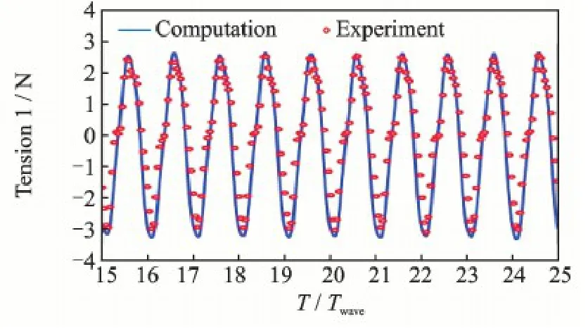
Fig.10 Time series of tension of tether 1
Besides the surging motion,the other two modes of motion are simulated and the time series of responses is shown in Fig.12.The amplitude of the heaving motion is 0.001 m,which is quite small when compared with the range of surge.The amplitude of pitch is 0.004 rad and the distance turbine and the center of gravity is 1.61 m.It should be noted that the displacement caused by pitching motion is 0.006 m which is still much smaller than that caused by surging motion.These are the features of TLP structures because the constraints of tethers are strong to depress heaving and pitching motions.
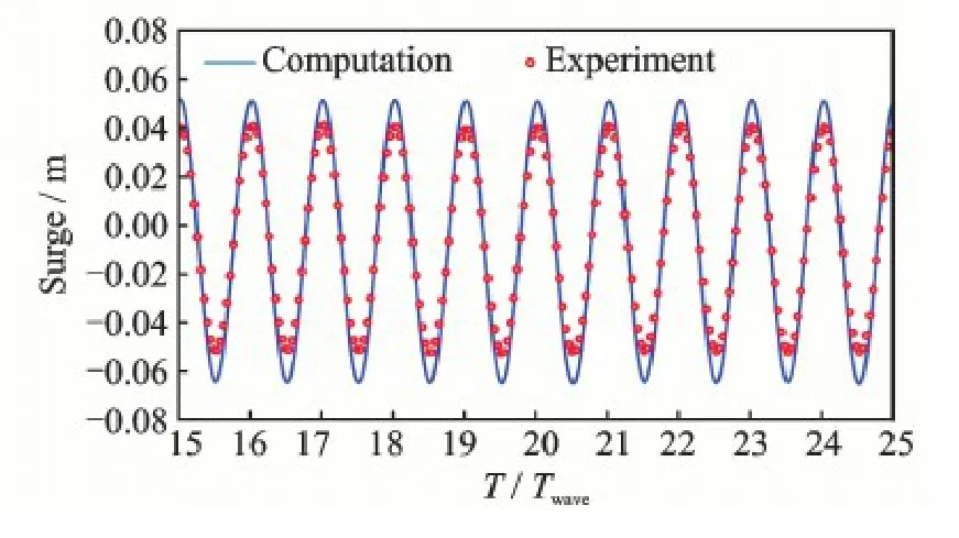
Fig.11 Time series of surging motion
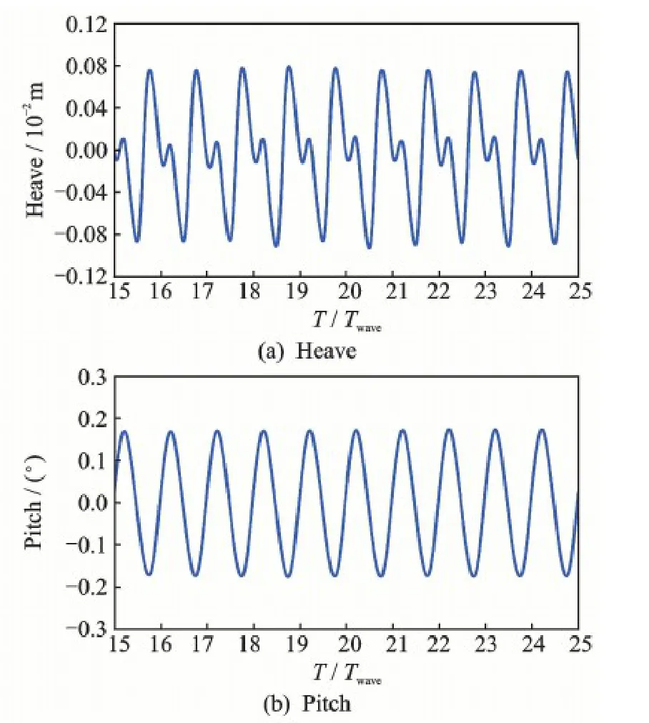
Fig.12 Time series of heave and pitch
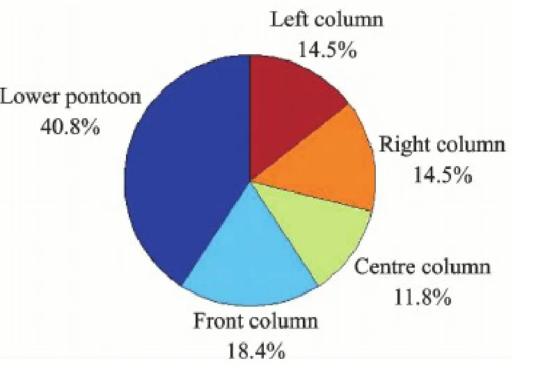
Fig.13 Proportional distribution of drags on different parts
4 Conclusions
An NWT is developed here based on the Opensource OpenFOAM.The decay process in calm water and the motion responses of it in regular waves are conducted numerically.The computed values match the experimental data,which proves the capability of model.For the attenuation frequencies of pitch,the difference between the computed value and measured data from model test is mainly caused by the flexibility of FOWT tower.Under effect of regular waves,the displacement caused by surging motion is the greatest among that of other two modes while it still meets the conceptual design requirements.The drag on the lower pontoon is the largest and the drag on the center column is the smallest.It turns out that,although thegeometry of the front column,right column and left column are the same,the drag on the front column is the greatest among these three columns because of the different trim angles of the columns.
Acknowledgements
This work was supported by the National Basic Research Program of China (″973″Program) (No.2014CB-046200) and the National Natural Science Foundation of China (No.11572196).
References:
[1]YANG H Z,ZHU Y,LU Q J,et al.Dynamic reliability based design optimization of the tripod sub-structure of offshore wind turbines[J].Renewable Energy,2015,78: 16-25.
[2]ADAM F,MYLAND T,SCHULDT B,et al.Evaluation of internal force superposition on a TLP for wind turbines[J].Renewable Energy,2014,71: 271-275.
[3]ANTONUTTI R,PEYRARD C,JOHANNING L,et al.An investigation of the effects of wind-induced inclination on floating wind turbine dynamics: heave plate excursion[J].Ocean Engineering,2014,91: 208-217.
[4]CAO J F,WANG T G,LONG H,et al.Dynamic loads and wake prediction for large wind turbines based on free wave method[J].Transactions of Nanjing University of Aeronautics and Astronautics,2015,32(2) : 240-249.
[5]LEE J H,KIM J K.Dynamic response analysis of a floating offshore structure subjected to the hydrodynamic pressures induced from seaquakes[J].Ocean Engineering,2015(101) : 25-39.
[6]FARRUGIA R,SANT T,MICALLEF D.Investigating the aerodynamic performance of a model offshore floating wind turbine[J].Renewable Energy,2014,70: 24-30.
[7]KE S T,HU F,CAO J F,et al.Simulation study on dynamic characteristic of floating offshore wind turbine systems[J].Journal of Nanjing University of Aeronautics&Astronautics,2015,47(4) : 595-601.(in Chinese)
[8]BAE Y H,KIM M H.Rotor-floater-tether coupled dynamics including second-order sum-frequency wave loads for a mono-column-TLP-type FOWT (floating offshore wind turbine)[J].Ocean Engineering,2013,61: 109-122.
[9]MA Q W,PATEL M H.On the no-linear forces acting on a floating spar platform in ocean waves[J].Applied Ocean Research,2001,23(1) : 29-40.
[10]YAN S,MA Q W.Numerical simulation of fully nonlinear interaction between steep waves and 2D floating bodies using the QALE-FEM method[J].Journal of Computational Physics,2007,221(2) : 666-692.
[11]LU Y J,LIU H,WU W,et al.Numerical simulation of two-dimensional overtopping against seawalls armored with artificial units in regular waves[J].Journal of Hydrodynamics: Ser.B,2007,19(3) : 322-329.
[12]GUO X Y,WANG B L,LIU H,et al.Numerical simulation of 2D regular wave overtopping flows over the crest of a trapezoidal smooth impermeable sea dike[J].J of Waterway,Port,Coastal and Ocean Engineering,ASCE,2014,140(3) : 04014006.
[13]WESTPHALEN J,GREAVES D M,WILLIAMS C J K,et al.Focused waves and wave-structure interaction in a numerical wave tank[J].Ocean Engineering,2012,45: 9-21.
[14]JACOBSEN N G,FUHRMAN D R,FREDSOE J.A wave generation toolbox for the open-source CFD library: OpenFoam®[J].International Journal for Numerical Methods in Fluids,2012,70(9) : 1072-1088.
[15]CHEN L F,ZANG J,HILLIS A J,et al.Numerical investigation of wave-structure interaction using Open-FOAM[J].Ocean Engineering,2014,88: 91-109.
Mr.Fan Xiang is currently a Ph.D.candidate of fluid mechanics in Department of Engineering Mechanics at Shanghai Jiao Tong University (SJTU).He received the B.S.degree in harbor and waterway engineering at Hohai University.The subject of his Ph.D.thesis is " hydrodynamic performance of a new offshore floating wind turbine".
Dr.Zhang Jingxin is currently an associate professor of fluid mechanics in Department of Engineering Mechanics at SJTU.He received his first degree and Ph.D.degree in SJTU.His research interests are computational fluid dynamics and environmental hydrodynamics.
Dr.Liu Hua is a professor of fluid mechanics at SJTU.He received his first degree in ocean engineering hydrology,M.S.degree in coastal engineering at Hohai University.He received Ph.D.degree in fluid mechanics at SJTU and then he joined the faculty of engineering mechanics at SJTU.His research interests are water wave dynamics and hydrodynamics at high speed.
(Executive Editor: Zhang Tong)
猜你喜欢
杂志排行
Transactions of Nanjing University of Aeronautics and Astronautics的其它文章
- Gravity Effect on the First Natural Frequency of Offshore Wind Turbine Structures
- Critical Stokes Number for Gas-Solid Flow Erosion of Wind Turbine Airfoil
- Coupled Aerodynamic and Hydrodynamic Analysis of Floating Offshore Wind Turbine Using CFD Method
- CFD-Based Load Calculation Method for Monopile Support Configuration of Offshore Wind Turbine
- Simulation of SLD Impingement on Wind Turbine Blade Airfoil
- Improvement of Mechanical,Dynamic-Mechanical and Thermal Properties for Noil Ramie Fiber Reinforced Polyethylene Composites
