Critical Stokes Number for Gas-Solid Flow Erosion of Wind Turbine Airfoil
2016-05-12LiDeshunGongYuxiangLiRennianLiYinranMaRuijieSchoolofEnergyandPowerEngineeringLanzhouUniversityofTechnologyLanzhou730050ChinaGansuProvincialTechnologyCentreforWindTurbinesLanzhou730050ChinaKeyLaboratoryofFluidMachinery
Li Deshun,Gong Yuxiang,Li Rennian,2,3,Li Yinran,2,3,Ma Ruijie.School of Energy and Power Engineering,Lanzhou University of Technology,Lanzhou 730050,P.R.China; 2.Gansu Provincial Technology Centre for Wind Turbines,Lanzhou 730050,P.R.China; 3.Key Laboratory of Fluid Machinery and Systems,Lanzhou 730050,P.R.China(Received 8 September 205; revised 20 December 205; accepted 5 January 206)
Critical Stokes Number for Gas-Solid Flow Erosion of Wind Turbine Airfoil
Li Deshun1,2,3*,Gong Yuxiang1,Li Rennian1,2,3,Li Yinran1,2,3,Ma Ruijie1
1.School of Energy and Power Engineering,Lanzhou University of Technology,Lanzhou 730050,P.R.China; 2.Gansu Provincial Technology Centre for Wind Turbines,Lanzhou 730050,P.R.China; 3.Key Laboratory of Fluid Machinery and Systems,Lanzhou 730050,P.R.China
(Received 18 September 2015; revised 20 December 2015; accepted 5 January 2016)
Abstract:Wind turbine blades are inevitable to be eroded in wind-sand environment,so it is crucial to identify the flow conditions under which the erosion happens.Here,the effect of the sand diameter on wind turbine airfoil is first investigated.When the sand diameter is less than 3 μm,the sands will bypass the airfoil and no erosion occurs.When the sand diameter is larger than 4 μm,the sand grains collide with the airfoil and the erosion happens.Thus,there must be a critical sand diameter between 3 μm and 4 μm,at which the erosion is initiated on the airfoil surface.To find out this critical value,a particle Stokes number is introduced here.According to the range of the critical sand diameter mentioned above,the critical value of particle Stokes number is reasonably assumed to be between 0.007 8 and 0.014.The assumption is subsequently validated by other four factors influecing the erosion,i.e.,the angle of attack,relative thickness of the airfoil,different series airfoil,and inflow velocity.Therefore,the critical range of Stokes number has been confirmed.
Key words:wind turbine airfoil erosion; critical Stokes number; gas-solid two-phase flow
CLC number: TK83Document code: AArticle ID: 1005-1120(2016)01-0067-06
* Corresponding author,E-mail address: lideshun_8510@ sina.com.
How to cite this article: Li Deshun,Gong Yuxiang,Li Rennian,et al.Critical Stokes number for gas-solid flow erosion of wind turbine airfoil[J].Trans.Nanjing Univ.Aero.Astro.,2016,33(1) : 67-72.
http: / /dx.doi.org/10.16356/j.1005-1120.2016.01.067
0 Introduction
Wind power,currently at the stage of scaleup development,is regarded as an important alternative power source.The wind resource in northwest China is abundant.Although it provides eligible renewable energy,the wind blows dust and sand,raising huge clouds of dust known as dust storm,one of wind-blown sand hazards.Wind turbine blades,running in such a harsh environment,suffer long-term erosion and the performance of wind turbine will degrade.The erosion eventually worsens the aerodynamic characteristics of wind turbine and reduces its annual power generation.Li et al.[1]pointed out that for the rough airfoil,the lift coefficient could decrease to about 40%and the drag coefficient could increase by ten times compared with that of the smooth one.Sareen et al.[2-5]investigated the effect of leading-edge erosion of wind turbine blade,and found that the blade leading-edge erosion could be extremely detrimental to wind turbine.The loss of annual energy production due to the impact of erosion could be as high as almost 25%for the modern wind turbines.Dong[6]studies the sand erosion behaviours of wind turbine blade materials by experimental method.
The critical Stokes number range of wind turbine airfoil erosion is discussed here via the numerical simulation based on particle transport model.The influences of other factors on the critical range are also analyzed.
1 Numerical Simulation
1.1Computational domain
The length and the width of three-dimensional (3-D) calculation domain are 32.5 times and 25 times larger than the airfoil chord length,respectively,as shown in Fig.1.And the blade span-wise width is 70 mm.Structured grid scheme is adopted to simulate the gas-solid two-phase flow.After verifying the validity of different scales of the grid structures,it is confirmed that the scheme,where the grid height of the first layer around the airfoil is selected for 0.01 mm,is the most suitable one for the calculation,as shown in Fig.2.
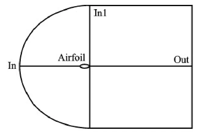
Fig.1 Schematic representation of computational domain
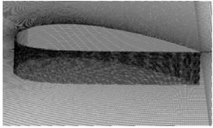
Fig.2 3-D grid around airfoil
1.2Computational models
Since the solid phase is dilute and its Mach number is lower than 0.3,the following assumptions are made: (1) The gas phase (air) is incompressible fluid and the solid phase (sand) the discrete phase.(2) The particle is uniform-sized spherical without phase transition.(3) The particle collision and the influence of particle rotation are ignored.The governing equations of the fluid phase are continuity equation and incompressible Reynolds-averaged Navier-Stokes equations (RANS),which are discretized by the method of finite volume.The turbulence mode is the standard k-ε model.And the semi-implicit method for pressure linked equations (SIMPLE) algorithm is used to solve the pressure-velocity coupling[7-8].The parameters of the fluid phase are 1.225 kg·m-3for the air density and 1.79×10⁻⁵kg·m-1·s-1for the air dynamic viscosity coefficient,respectively.The particle transport model is adopted to predict the solid phase movement.
1.3Boundary conditions
The velocity boundary condition is defined at inlet with a turbulence intensity of 10%.The pressure boundary condition is defined at outlet at one standard atmospheric pressure.According to the analysis of sand characteristics parameters under sandstorm environment in Refs.[9-11],in this paper,the dust concentration is fixed to 5 000 μg·m-3to study the erosion on wind turbine airfoil.Solid phase is injected into the flow field at the inlet,where the particles are uniformly distributed,and the injection velocity of solid phase is equal to that of gas phase.The sand density is 2 200 kg·m-3.There is no-slip velocity between solid phase and gas phase.Particle is completely escaped at outlet.The drag interaction between the two phases is described by the Schiller-Naumann model.The airfoil surface is regarded as a smooth wall.No-slip assumption is taken as the boundary condition,and the impact between the particle and airfoil is supposed as perfectly elastic collision.The erosion model established by Grant and Tabakoff[12]is used to study the erosion characteristics,and the maximum erosion angle is set as 90°because the epoxy gel-coat of blade is brittle.
2 Results and Discussions
2.1Proposal of critical Stokes number
The Stokes number of particle is the most important dimensionless parameter in a gas-solid two-phase flow,which is derived by Shvab and Evseev[13]to evaluate particle movement following the airflow.The Stokes number can be defined as the ratio of particle response time to the system response time,expressed by the equation
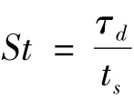
where τd=.tsis the time related to the character-istic length and the characteristic velocity vsof the system through the formula ts= Ls/vs.
For airfoil,the characteristic length is the chord length and the characteristic velocity is the inflow velocity.When St≪1.0,the particles will closely follow the gas phase flow.When St>1.0,the particles will move independently as the gas phase flows[14].
In this section,an airfoil of a wind turbine blade for field experiment[15]of Lanzhou University of Technology is chosen as research subject.The chord length of airfoil NACA4418 is 0.283 m.The relative inflow velocity is 36.36 m·s-1and the angle of attack of the airfoil is 9.47°.By simulating the influence of sand diameter on the NACA 4418 airfoil,it is found that when the sand diameter is less than 3 μm,the sands bypass the airfoil and no erosion occurs,as shown in Fig.3 (a).However,when the sand diameter is larger than 4 μm,a few sand particles collide with the airfoil and cause erosion,as shown in Fig.3(b).Therefore,when the velocity is 36.36 m·s-1,the erosion occurs with the diameter between 3 μm and 4 μm,which corresponds to the range of the particle Stokes number from 0.007 8 to 0.014.Typically,it can be assumed that there may exist a Stokes number critical range between 0.007 8 and 0.014 which can be used to forecast whether the erosion happens on wind turbine airfoil.
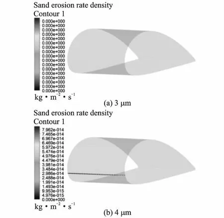
Fig.3 Erosion on airfoil with different sand diameters
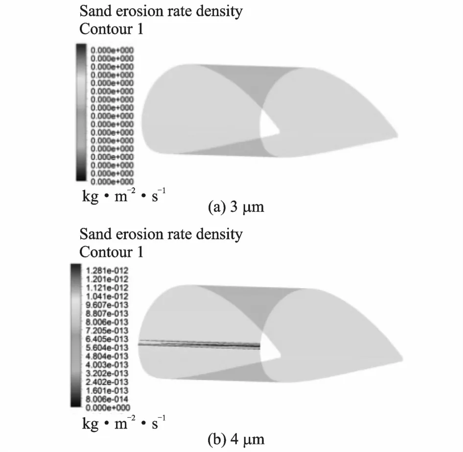
Fig.4 Erosion on airfoil with attack angle of 0°
2.2Validation
To validate the correctness of the Stokes number critical range,we discuss the effects of the angle of attack,relative thickness of airfoil,different series airfoil,and inflow velocity on airfoils erosion respectively.
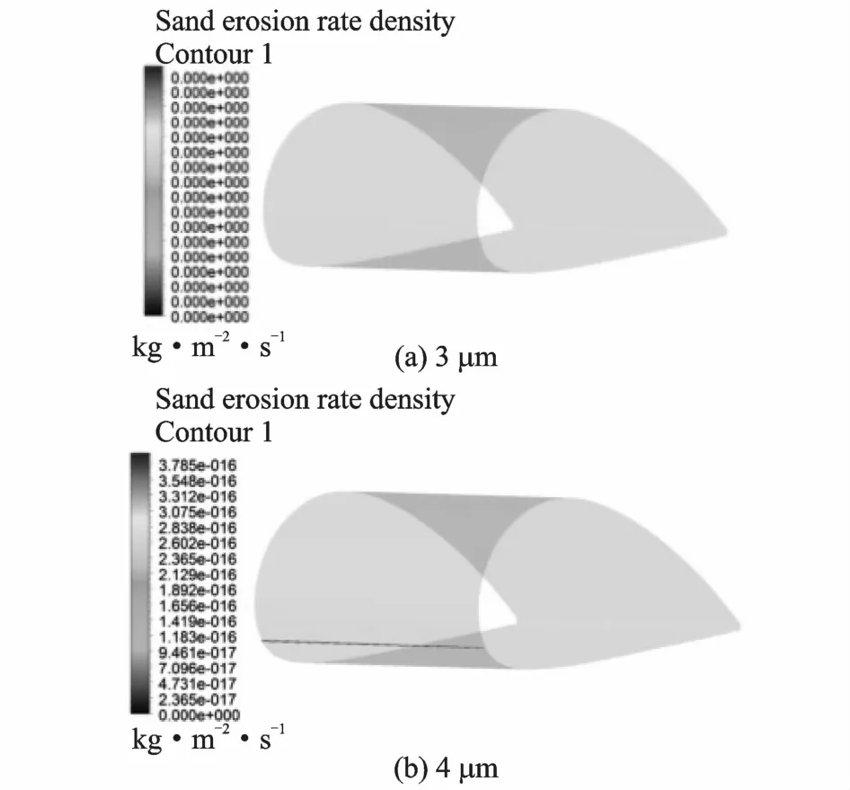
Fig.5 Erosion on airfoil with attack angle of 5°
Firstly,the effect of airfoil attack angle on the Stokes number critical range is investigated with three different attack angles of 0°,5°and 15°for the NACA 4418 airfoil at the inflow velocity of 36.36 m·s-1.The results are illustrated in Figs.4,5,6.It can be seen that for all the three different angles of attack no erosion takes place when the sand diameter is 3 μm,as shown in Figs.4 (a ),5 (a ),6 (a ).Nevertheless,when thesand diameter is 4 μm,the erosion happens in all the three cases,as shown in Figs.4(b),5(b),6(b).Therefore,it can be concluded that the angle of attack hardly influences the critical range of Stokes number.
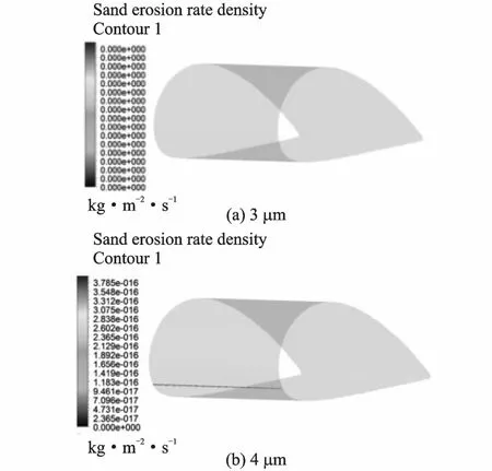
Fig.6 Erosion on airfoil with attack angle of 15°
Secondly,the critical ranges of Stokes number are calculated for three symmetrical airfoils,i.e.,NACA 0012,NACA 0018 and NACA 0024,to verify that the critical range of Stokes number is irrelevant to relative airfoil thickness.It is revealed that sands do not erode the airfoil at all for all the three different relative thickness when the sand diameter is 3 μm,as shown in Figs.7(a),8(a),9(a).When the sand diameter is 4 μm,the airfoil erosion occurs on all the three cases as shown in Figs.7(b),8(b),9(b).Therefore,the critical range of Stokes number is not affected by relative airfoil thickness.
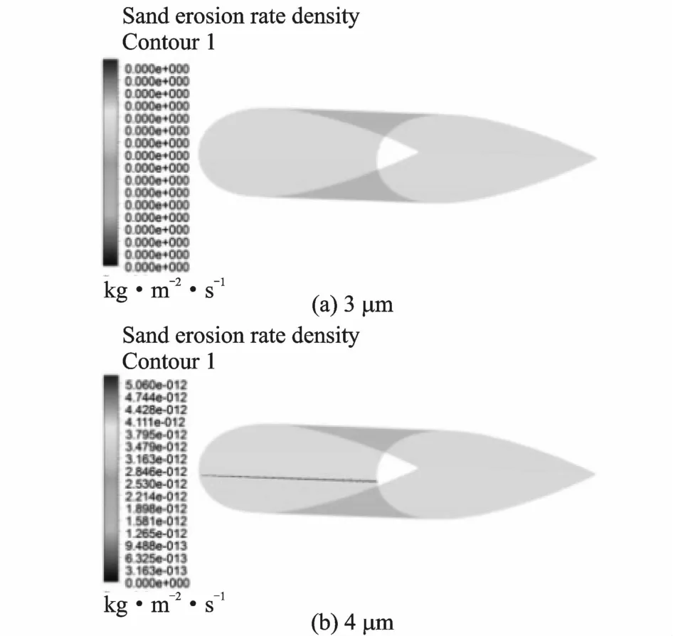
Fig.7 Erosion on NACA 0012 airfoil
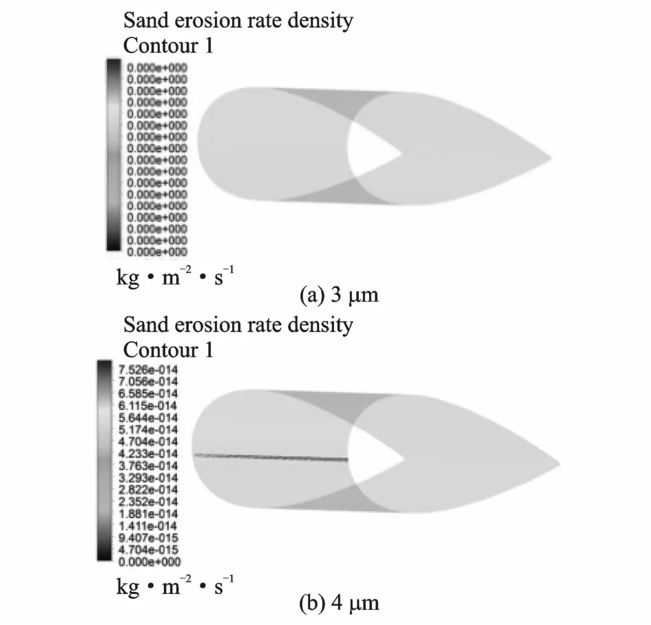
Fig.8 Erosion on NACA 0018 airfoil
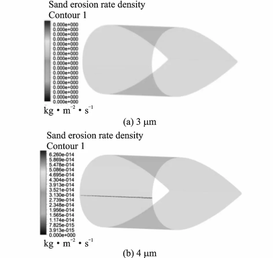
Fig.9 Erosion on NACA 0024 airfoil
In order to find out whether the critical range of Stokes number is also appropriate to other series airfoil,the airfoil DU 91-W2-250,which can represent the DU series airfoils,was selected in the simulation.It is demonstrated that both the NACA series airfoil and other airfoil series are appropriate for the critical range of Stocks number.It is obvious that there is no erosion when the sand diameter is 3 μm,as shown in Fig.10(a).Whereas with the sand diameter of 4 μm,the erosion occurs on the airfoil,as shown in Fig.10(b).Therefore,we confirm that the critical range of Stokes number is irrelevant to airfoil series.
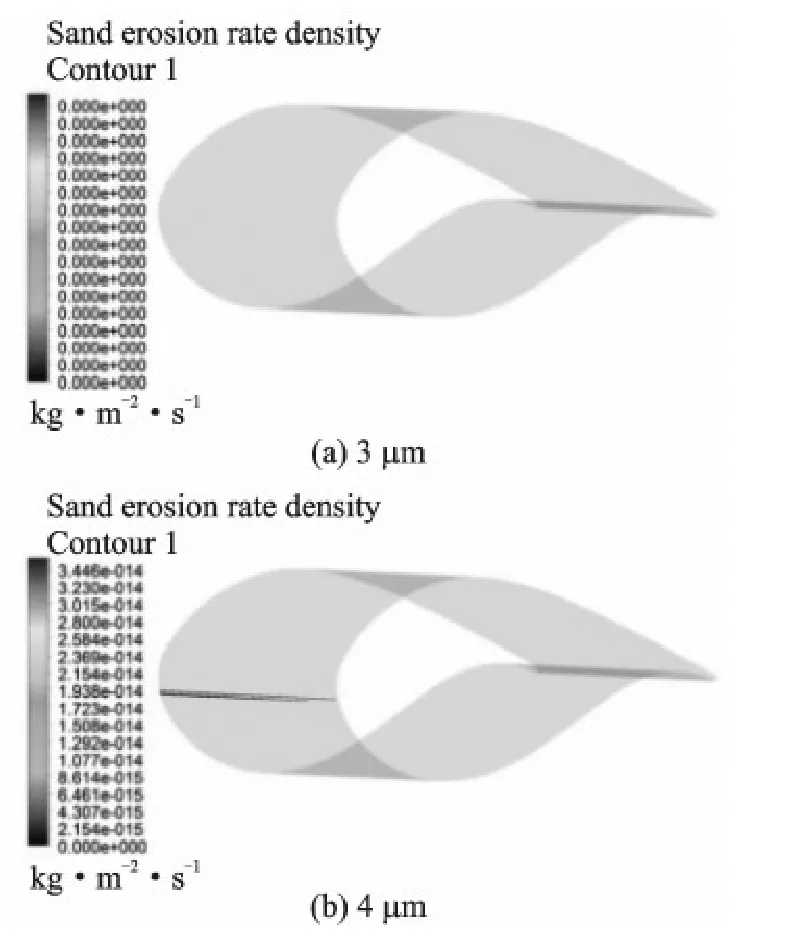
Fig.10 Erosion on DU 91-W2-250 airfoil
Stokes number is irrelevant to airfoil series.
Finally,the inflow velocity is introduced to examine the airfoil erosion.It is found that when the inflow velocity is 18 m/s and the sand diameter 4 μm,the Stokes number is 0.006 95 without any erosion on the airfoil.While the sand diameter is 5 μm,the Stokes number is 0.010 86,and the erosion occurs on the airfoil.When the inflow velocity is 50 m/s and the sand diameter 2 μm,the Stokes number is 0.004 83 which is less than 0.007 8,and there is no erosion on the airfoil; When the sand diameter is 3 μm,the Stokes number is 0.010 86,and the erosion occurs on the airfoil.Conclusions can be drawn that the erosion is not going to happen when the Stokes number is less than 0.007 8,as shown in Figs.11(a),12(a).But the airfoil is eroded when the Stokes number is larger than 0.010 86,as shown in Figs.11 (b),12 (b).Thus,the critical range of Stokes number can be narrowed to the one between 0.007 8 and 0.010 86.
3 Conclusions
The critical range of particle Stokes number is proposed by analyzing the effect of sand diameter on the wind turbine airfoil gas-solid two-phase flow erosion to determine the specific flow conditions under which the erosion occurs.The critical range of Stokes number is confirmed to be between 0.007 8 and 0.010 86 by addressing the effects of other factors, such as angle of attack,relative thickness of airfoil,different airfoil series,and inflow velocity.
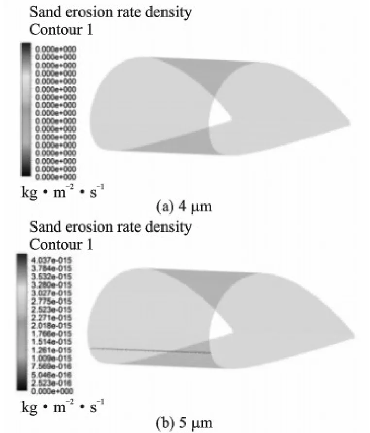
Fig.11 Erosion at velocity of 18 m·s-1
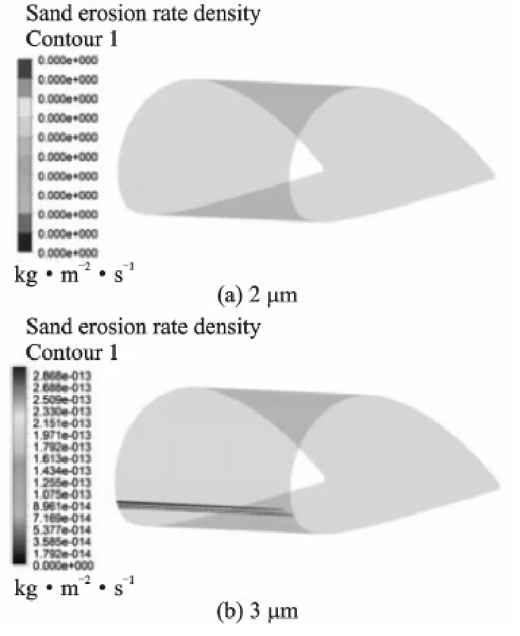
Fig.12 Erosion at velocity of 50 m·s-1
Acknowledgements
This work was supported partly by the National Basic ResearchProgramof China (″973″Program )(No.2014CB046201),the National Natural Science Foundation of China (No.51166009),the National High Technology ResearchandDevelopment Programof China(No.2012AA052900),the Natural Science Foundation of Gansu Province,China (No.1308RJZA283,145RJZA059) and the Gansu Province University Scientific Research Project,China (No.2013A-026).The authors would like to thank Mr.Li Qiuyan,Mr.Wang Chengze and Mr.Liu Heng for their assistance.
References:
[1]HUANG Chenwu,YANG Ke,LIU Qiang,et al.A study on performance influences of airfoil aerodynamic parameters and evaluation indicators for the roughness sensitivity on wind turbine blade[J].Science China Technological Sciences,2011,54(11) : 2993-2998.
[2]SAREEN A,SAPRE C A,SELIG M S.Effect of leading-edge erosion on wind turbine blade performance [J].Wind Energy,2014,17 (10) : 1531-1542.
[3]SAREEN A,SAPRE C A,SELIG M S.Effects of leading-edge protection tape on wind turbine blade performance[J].Wind Engineering,2012,36(5) : 525-534.
[4]SAYER F,BURKNER F,BUCHHOLZ B,et al.Influence of a wind turbine service life on the mechanical properties of the material and the blade[J].Wind Energy,2013,16(2) : 163-174.
[5]CHEN Weijian,ZHANG Dalin.Prediction of rime ice accretion and resulting effect on airfoil performance[J].Transactions of Nanjing University of Aeronautics and Astronautics,2005,22(1) : 9-15.
[6]DALILI N,EDRISY A,CARRIVAU R.A review of surface engineering issues critical to wind turbine performance[J].Renewable and Sustainable Energy Reviews,2009,13(2) : 428-438
[7]DALILI N,EDRISY A,CARRIVEAU R.A review of surface engineering issues critical to wind turbine performance[J].Renewable and Sustainable Energy Reviews,2009,13(2) : 428-438.
[8]LI D S,LI R N.Field experiment of blade surface pressure of a HAWT[J].Applied Mechanics and Materials,2013,291: 445-449.
[9]JIAO M Y,ZHAO L N,LU J J,et al.Quantitative classification of northeast asian dust weather and its applications[J].Climatic and Environmental Research,2007,12 (3) : 350-357.(in Chinese)
[10]LIU XinChun,ZHONG Yuting,HE Qing,et al.Analysis of mass concentration of atmospheric particulate matter in a sandstorm course and its affecting factors in the Taklimakan Desert[J].Sciences in Cold and Arid Regions,2012,3: 259-264.
[11]WANG W,SONG Z X,SHAO Y P,et al.Numerical simulation and forecast system of dust storms and its performance test[J].Meteorological Science and Technology,2005,33(1) : 25-31.(in Chinese)
[12]GRANT G,TABAKOFF W.An experimental investigation of the erosive characteristics of 2024 aluminum alloy [R].Report No.73-37,Cincinnati Univ Oh Dept of Aerospace Engineering,USA,1973.
[13]SHVAB A,EVSEEV N.Studying the separation of particles in a turbulent vortex flow[J].Theoretical Foundations of Chemical Engineering,2015,49(2) : 191-199.
[14]XU W J,CHE D F,XU T M.Relaxation process of sand particles[J].Journal of Xi'an Jiaotong University,2005,39 (5) : 536-539.(in Chinese)
[15]LI D S,LI R N,WANG X Y,et al.Investigation of three-dimensional effect on blades of a wind turbine based on field experiments[J].Applied Mathematics and Mechanics,2013,34(10) : 1073-1082.(in Chinese)
Dr.Li Deshun is the deputy director of Gansu Provincial Technology Centre for Wind Turbines,associated professor and master tutor of Lanzhou University of Technology.His main research interests lie in the wind turbine aerodynamics.
Mr.GongYuxiang received the M.S.Degree in Lanzhou University of Technology and his main research interests are wind turbine aerodynamics.
Dr.Li Rennian is the Vice President,professor and doctoral supervisor in Lanzhou University of Technology,specializing in the research of wind turbine aerodynamics and fluid machinery.
Mr.Li Yinran is an Ph.D.candidate in Lanzhou University of Technology.His main research interests are wind turbine aerodynamics.
Ms.Ma Ruijie now is studying in Lanzhou University of Technology for the M.S.Degree.Her current research interests focus on the wind turbine aerodynamics.
(Executive Editor: Zhang Tong)
杂志排行
Transactions of Nanjing University of Aeronautics and Astronautics的其它文章
- Gravity Effect on the First Natural Frequency of Offshore Wind Turbine Structures
- Numerical Analysis on Motion of Multi-column Tension-Leg-Type Floating Wind Turbine Basement
- Coupled Aerodynamic and Hydrodynamic Analysis of Floating Offshore Wind Turbine Using CFD Method
- CFD-Based Load Calculation Method for Monopile Support Configuration of Offshore Wind Turbine
- Simulation of SLD Impingement on Wind Turbine Blade Airfoil
- Improvement of Mechanical,Dynamic-Mechanical and Thermal Properties for Noil Ramie Fiber Reinforced Polyethylene Composites
